EP1179639A2 - Schneepflug - Google Patents
Schneepflug Download PDFInfo
- Publication number
- EP1179639A2 EP1179639A2 EP01118578A EP01118578A EP1179639A2 EP 1179639 A2 EP1179639 A2 EP 1179639A2 EP 01118578 A EP01118578 A EP 01118578A EP 01118578 A EP01118578 A EP 01118578A EP 1179639 A2 EP1179639 A2 EP 1179639A2
- Authority
- EP
- European Patent Office
- Prior art keywords
- frame
- snow plow
- ploughshare
- plow according
- support element
- Prior art date
- Legal status (The legal status is an assumption and is not a legal conclusion. Google has not performed a legal analysis and makes no representation as to the accuracy of the status listed.)
- Withdrawn
Links
Images


Classifications
-
- E—FIXED CONSTRUCTIONS
- E01—CONSTRUCTION OF ROADS, RAILWAYS, OR BRIDGES
- E01H—STREET CLEANING; CLEANING OF PERMANENT WAYS; CLEANING BEACHES; DISPERSING OR PREVENTING FOG IN GENERAL CLEANING STREET OR RAILWAY FURNITURE OR TUNNEL WALLS
- E01H5/00—Removing snow or ice from roads or like surfaces; Grading or roughening snow or ice
- E01H5/04—Apparatus propelled by animal or engine power; Apparatus propelled by hand with driven dislodging or conveying levelling elements, conveying pneumatically for the dislodged material
- E01H5/06—Apparatus propelled by animal or engine power; Apparatus propelled by hand with driven dislodging or conveying levelling elements, conveying pneumatically for the dislodged material dislodging essentially by non-driven elements, e.g. scraper blades, snow-plough blades, scoop blades
Definitions
- the present invention relates to a snow plow with a ploughshare suspended from a frame and a carrying device, the carrying device being a an attachment element that can be attached to a carrier vehicle, a support element and one the attachment element with the support element connecting connecting arrangement and the Frame pivotable about a substantially vertical axis is mounted on the support element, and wherein at least one variable-length adjustment element on the one hand on the frame and on the other hand on the support element attacks.
- the suspension of a snow plow on a carrier vehicle must allow the snow plow to be relative to the Carrier vehicle occupies different positions. To the the snow plow must be raised and lowered can be. Furthermore, the ploughshare must pivot a substantially vertical axis leave to change the direction of ejection of the snow plow and the angle of the ploughshare to the direction of travel to be able to adjust. Usually is beyond also provided that the ploughshare relative to Carrier vehicle around a substantially horizontal, axis pivoted in the direction of travel can (commute), so that the ploughshare on a possible side slope of the road surface adjust and / or a side slope of the Carrier vehicle especially when driving through Can compensate for curves.
- Typical snow plows are from, for example EP 0111882 A3, DE 29503668 U1 and DE 3932944 A1 known.
- the support device comprises a connection arrangement each have a handlebar assembly that Raising and lowering the ploughshare and the frame comprehensive unity.
- To the frame with the ploughshare suspended from it by an essentially being able to swivel the vertical axis are two hydraulic swivel cylinders provided the one hand on the attachment of the support device and on the other hand attack the frame.
- adjustment cylinder can be from the Ploughshare and the existing unit also in bring a middle position in which the ploughshare extends exactly across the direction of travel.
- DE 4230517 A1 discloses a snow plow in which the change in the angle of attack from the ploughshare and the existing unit for the direction of travel with a translational shift of those Unity goes to the side. This is achieved through a support of the frame on the attachment of the Carrying device by means of a handlebar arrangement, the several converging in the plan view in the direction of travel Handlebar includes. This is said to be independent of the respective angle of attack as constant as possible Center alignment of the ploughshare to achieve a at least largely related to symmetrical clearing position be reached on the commercial vehicle carrying the plow.
- the two swivel cylinders are also supported here on the one hand on the frame and on the other hand on the Attachment element of the support device.
- the CH 665237 A5 discloses a handlebar arrangement for Support of a ploughshare on the chassis of a carrier vehicle.
- the handlebar arrangement is around a modified three-link support, two the three handlebars are adjustable in length to the ploughshare swivel or change their inclination to can.
- the decisive one for a pivoting movement The axis lies in the area of the articulation point of the third, non-variable handlebar on the Ploughshare, this handlebar using a diagonal strut on the chassis of the carrier vehicle is supported.
- snow plows of the generic type were developed, where the adjustment elements are not on the add-on element support the support device but rather on the support element of the support device.
- the "VECTOR” TM series from Schmidt Winterdienst and Varunaltechnik GmbH known (see e.g. the company brochure Schmidt's "winter service product range” Winterdienst- und Merouraltechnik GmbH, printing notice 553 MBM 31099).
- For plows of the generic type is the swiveling movement of the snow plow around the essential vertical axis strictly separated from the other possibilities of movement of the ploughshare.
- the snow plows are therefore of the generic type in terms of their relevant properties State of the art explained at the beginning think.
- One disadvantage of the snow plows the generic type is the large front dimension, i.e. the large distance of the ploughshare in front of the Carrier vehicle. Especially against the background that Snow plows designed for large clearing widths extremely are difficult, a reduction of the front dimension would be too welcome to the driving characteristics of the carrier vehicle to improve.
- the present invention is derived from this underlying task from that in it there is a snow plow of the type mentioned to create, which is characterized by a reduced stem size distinguished without causing any impairment the pivotability of the ploughshare and / or for pivoting through the at least one Adjustment element provided torque would result.
- the specified task is solved according to the present invention in that the articulation point of at least one adjustment element on the support element in Working direction is in front of the swivel axis.
- the Snow plow according to the invention distinguishes itself with others Words from that - in the working direction seen - foremost point of the support element not through the swivel over which the frame can be swiveled with the support element is connected, is formed, but that rather part of the support member on the Projecting pivot axis beyond, which is at least one Adjustment element at that point above Supporting element is articulated.
- This design of the Snow plow enables at least one Adjustment element in the immediately behind the Ploughshare to accommodate arranged space, i.e.
- a first preferred development of the invention is characterized in that the articulation point of the at least one adjustment element on the support element is centered in front of the swivel axis.
- there are particularly favorable kinematic Relationships within the overall system namely among other things, because in all Swivel positions of the ploughshare (right-left-center) result in almost equal leverage ratios.
- Another preferred development of the invention is characterized in that two in plan view symmetrically arranged adjustment elements are provided are. It is preferred if the two Adjustment elements on the same, in the middle of the Pivot axis arranged pivot point of the support element attack. This results in a particularly compact one Construction of the snow plow with a high swivel torque and particularly favorable kinematic conditions. moreover in this case, provided the two adjustment elements are designed as hydraulic cylinders, a connection of the two hydraulic cylinders via one Compensation line possible, which in the event of overload (e.g. Approaching an obstacle) swiveling the Ploughshare allows without hydraulic fluid in the tank is pushed back.
- overload e.g. Approaching an obstacle
- the at least one Adjustment element is housed particularly protected.
- the rear, the carrier vehicle facing side of the frame free for further Functional parts of the snow plow such as Support elements (skids or rollers) or the like.
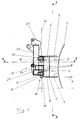
- the snow plow shown in the drawing includes a ploughshare with three coulters 1. Each of the three coulters is with a handlebar arrangement three upper links 2 and three lower links 3 hung on a frame 4.
- the top and bottom Handlebars 2 and 3 are made of an elastomer Made of material.
- the frame 4 consists of an upper box beam 5, a lower box girder 6 and two connectors 7.
- the the upper link 2 are on the upper box beam 5 and the lower link 3 are on the lower Box girder 6 struck.
- the hinge plates 8 and 9 form the frame-side component of a swivel joint 10, by means of which the frame 4 about a vertical axis 11 pivotable on the support member 12 one Support device, which is a (not shown) connection arrangement in the form of a Handlebar arrangement and a (also not shown) Attachment includes, is stored.
- the swivel joint 10 further includes an upper and a lower one Bolt 13 or 14, which in an upper eye 15 or a lower eye 16 of the support element is guided.
- the upper eye 15 and lower eye 16 are fixed connected to the main support 17 of the support member 12.
- the two adjusting elements 18 For pivoting the ploughshare 1 and the frame 4 comprehensive unit around the pivot axis 11 are two adjusting elements 18 in the form of hydraulic cylinders 19 provided.
- the two hydraulic cylinders 19 are thereby symmetrical in the top view (Fig. 3) arranged.
- Both hydraulic cylinders 19 are with each one end at a common pivot point 20 struck, which is centered on a stem 21 of the Support element 12 in the working direction A by the distance s is arranged in front of the pivot axis 11.
- the other end each of the two hydraulic cylinders 19 is on one Bearing bracket 22 struck, firmly on one the two connectors 7 is attached.
- the common one Articulation point 20 of the two hydraulic cylinders is located in working direction A in front of a straight line, which the Articulation points 23 of the two hydraulic cylinders 19 on the Frame 4 connects together. This results in a rear-open V-shaped arrangement of the two hydraulic cylinders 19 in the in the drawing illustrated middle position of the ploughshare.
- the stem 21 of the support member 12 is in essentially of two superimposed in essential triangular plates between which defining a common pivot point 20 Bolt extends.
- In the rear area are the Stem 21 sideways of the main beam 17 of the Support element 12 connecting elements 24 for connecting a Handlebar assembly attached. Further connection plates 25 are provided on the head of the main support 17.
Landscapes
- Engineering & Computer Science (AREA)
- Architecture (AREA)
- Civil Engineering (AREA)
- Structural Engineering (AREA)
- Cleaning Of Streets, Tracks, Or Beaches (AREA)
- Fittings On The Vehicle Exterior For Carrying Loads, And Devices For Holding Or Mounting Articles (AREA)
Abstract
Description
- Fig. 1
- eine Seitenansicht des betreffenden Schneepflugs (ohne Anbauelement und Verbindungsanordnung der Trageinrichtung),
- Fig. 2
- einen Vertikalschnitt durch den Schneepflug gemäß Fig. 1 entlang der Linie II-II und
- Fig. 3
- einen Horizontalschnitt durch den Schneepflug gemäß den Fig. 1 und 2 entlang der Linie III-III.
Claims (9)
- Schneepflug mit einer an einem Rahmen (4) aufgehängten Pflugschar (1) und einer Trageinrichtung, wobei die Trageinrichtung ein an einem Trägerfahrzeug anbaubares Anbauelement, ein Tragelement (12) und eine das Anbauelement mit dem Tragelement (12) verbindende Verbindungsanordnung aufweist und der Rahmen (4) um eine im wesentlichen vertikale Achse (11) verschwenkbar an dem Tragelement (12) gelagert ist, und wobei mindestens ein längenveränderliches Verstellelement (18) einerseits an dem Rahmen (4) und andererseits an dem Tragelement (12) angreift,
dadurch gekennzeichnet, daß der Anlenkpunkt (20) des mindestens einem Verstellelements (18) an dem Tragelement (12) in Arbeitsrichtung (A) vor der Schwenkachse (11) liegt. - Schneepflug nach Anspruch 1,
dadurch gekennzeichnet, daß der Anlenkpunkt (20) des mindestens einem Verstellelements (18) an dem Tragelement (12) mittig vor der Schwenkachse (11) liegt. - Schneepflug nach Anspruch 1 oder Anspruch 2,
dadurch gekennzeichnet, daß zwei in Draufsicht symmetrisch angeordnete Verstellelemente (18) vorgesehen sind. - Schneepflug nach Anspruch 3,
dadurch gekennzeichnet, daß die beiden Verstellelemente (18) an demselben Anlenkpunkt (20) des Tragelements (12) angreifen. - Schneepflug nach Anspruch 4,
dadurch gekennzeichnet, daß die beiden Verstellelemente (18) in vertikaler Richtung auf unterschiedlich hohem Niveau angeordnet sind. - Schneepflug nach einem der Ansprüche 3 bis 5,
dadurch gekennzeichnet, daß in der Mittelstellung der Pflugschar (1) der Anlenkpunkt (20) der beiden Verstellelemente (18) an dem Tragelement (12) vor einer Geraden liegt, welche die Anlenkpunkte (23) der beiden Verstellelemente (18) an dem Rahmen (4) verbindet. - Schneepflug nach einem der Ansprüche 1 bis 6,
dadurch gekennzeichnet, daß die Pflugschar (1) mittels einer eine Ausweichbewegung ermöglichenden Verbindungsanordnung am Rahmen (4) aufgehängt ist. - Schneepflug nach Anspruch 7,
dadurch gekennzeichnet, daß die Pflugschar (1) mittels einer Lenkeranordnung (2, 3) am Rahmen (4) aufgehängt ist. - Schneepflug nach einem der Ansprüche 1 bis 8,
dadurch gekennzeichnet, daß das mindestens eine Verstellelement (18) als Hydraulikzylinder (19) ausgeführt ist.
Applications Claiming Priority (2)
| Application Number | Priority Date | Filing Date | Title |
|---|---|---|---|
| DE2000139259 DE10039259C2 (de) | 2000-08-11 | 2000-08-11 | Schneepflug |
| DE10039259 | 2000-08-11 |
Publications (2)
| Publication Number | Publication Date |
|---|---|
| EP1179639A2 true EP1179639A2 (de) | 2002-02-13 |
| EP1179639A3 EP1179639A3 (de) | 2003-10-08 |
Family
ID=7652110
Family Applications (1)
| Application Number | Title | Priority Date | Filing Date |
|---|---|---|---|
| EP01118578A Withdrawn EP1179639A3 (de) | 2000-08-11 | 2001-08-02 | Schneepflug |
Country Status (2)
| Country | Link |
|---|---|
| EP (1) | EP1179639A3 (de) |
| DE (1) | DE10039259C2 (de) |
Cited By (1)
| Publication number | Priority date | Publication date | Assignee | Title |
|---|---|---|---|---|
| NO20060482L (no) * | 2006-01-30 | 2007-07-31 | Tellefsdal As | Festeinnretning for montering av redskap på kjøretøy |
Citations (4)
| Publication number | Priority date | Publication date | Assignee | Title |
|---|---|---|---|---|
| EP0111882A2 (de) | 1982-12-13 | 1984-06-27 | Ing. Alfred Schmidt Gmbh | Schneepflug |
| DE3932944A1 (de) | 1988-10-06 | 1990-04-12 | Schmidt Alfred Ing Gmbh | Vorrichtung zum anbau eines schneepfluges an ein fahrzeug |
| DE4230517A1 (de) | 1992-09-11 | 1994-03-17 | Beilhack Maschf Martin | Schneepflug |
| DE29503668U1 (de) | 1995-01-10 | 1995-04-20 | Kahlbacher, Anton, Ulmerfeld-Hausmening | Schneepflug mit mindestens einer Pflugschar |
Family Cites Families (7)
| Publication number | Priority date | Publication date | Assignee | Title |
|---|---|---|---|---|
| DE2438514B2 (de) * | 1974-08-10 | 1976-12-16 | Martin Beilhack Maschinenfabrik Und Hammerwerk Gmbh, 8200 Rosenheim | Schneepflug |
| CH665237A5 (en) * | 1984-05-29 | 1988-04-29 | Viktor Meili Ag Fuer Konstrukt | Bulldozer blade mounting - has double acting rams with linkage on horizontal vehicle axis to blade end hinge |
| DE3439506C1 (de) * | 1984-10-27 | 1986-03-27 | Ing. Alfred Schmidt Gmbh, 7822 St Blasien | Schneepflug |
| DE3602758A1 (de) * | 1986-01-30 | 1987-08-20 | Daimler Benz Ag | Schneepflug |
| DE4305648B4 (de) * | 1992-02-24 | 2009-06-25 | Josef Nusser | Schwenkvorrichtung |
| US5899007A (en) * | 1996-06-07 | 1999-05-04 | Blizzard Corporation | Adjustable wing plow |
| US5974702A (en) * | 1998-06-01 | 1999-11-02 | Donoghue; John Barry | Snow plow mounting assembly |
-
2000
- 2000-08-11 DE DE2000139259 patent/DE10039259C2/de not_active Expired - Fee Related
-
2001
- 2001-08-02 EP EP01118578A patent/EP1179639A3/de not_active Withdrawn
Patent Citations (4)
| Publication number | Priority date | Publication date | Assignee | Title |
|---|---|---|---|---|
| EP0111882A2 (de) | 1982-12-13 | 1984-06-27 | Ing. Alfred Schmidt Gmbh | Schneepflug |
| DE3932944A1 (de) | 1988-10-06 | 1990-04-12 | Schmidt Alfred Ing Gmbh | Vorrichtung zum anbau eines schneepfluges an ein fahrzeug |
| DE4230517A1 (de) | 1992-09-11 | 1994-03-17 | Beilhack Maschf Martin | Schneepflug |
| DE29503668U1 (de) | 1995-01-10 | 1995-04-20 | Kahlbacher, Anton, Ulmerfeld-Hausmening | Schneepflug mit mindestens einer Pflugschar |
Cited By (1)
| Publication number | Priority date | Publication date | Assignee | Title |
|---|---|---|---|---|
| NO20060482L (no) * | 2006-01-30 | 2007-07-31 | Tellefsdal As | Festeinnretning for montering av redskap på kjøretøy |
Also Published As
| Publication number | Publication date |
|---|---|
| DE10039259C2 (de) | 2002-06-13 |
| DE10039259A1 (de) | 2002-03-07 |
| EP1179639A3 (de) | 2003-10-08 |
Similar Documents
| Publication | Publication Date | Title |
|---|---|---|
| DE2715375C3 (de) | Stellvorrichtung für ein landwirtschaftlich nutzbares Arbeitsgerät | |
| EP2408971B1 (de) | Auswechselbare kehrbürsteneinrichtung und kehrmaschine mit einer derartigen kehrbürsteneinrichtung | |
| EP0271645A1 (de) | Schneepflug | |
| EP0063774A1 (de) | Geräteanbauvorrichtung für ein landwirtschaftliches Arbeitsfahrzeug | |
| DE2035066B2 (de) | An ein Zugfahrzeug kuppelbares Planiergerät für den Bau oder Unterhalt von wassergebundenen Straßen | |
| EP0914761B1 (de) | Trägerfahrzeug mit einer Aufhängung für beidseitig an diesem angebrachte Arbeitsaggregate | |
| DE4018832B4 (de) | Schneepflug mit Räumschar | |
| DE4230517C2 (de) | Schneepflug | |
| EP0992371B1 (de) | Vorrichtung zum Kuppeln eines Antriebsfahrzeuges mit einem Koppelrahmen zur Aufnahme von Arbeitsgeräten | |
| DE2633428A1 (de) | Anbauvorrichtung zum anbau von geraeten, insbesondere schneeraeumgeraeten | |
| DE10039259C2 (de) | Schneepflug | |
| CH665237A5 (en) | Bulldozer blade mounting - has double acting rams with linkage on horizontal vehicle axis to blade end hinge | |
| EP0259801B1 (de) | Geräteanbauvorrichtung für landwirtschaftlich nutzbare Zugfahrzeuge | |
| EP0316825B1 (de) | Pflugrahmen | |
| EP0427149B1 (de) | Vorrichtung zum Anbau einer Landmaschine an einen Dreipunktbock | |
| DE19514013A1 (de) | Vorrichtung zum Anbau eines Vorbauarbeitsgerätes | |
| EP4252503B1 (de) | Landwirtschaftlicher mäher zum betreiben im schubbetrieb | |
| DE4015862A1 (de) | Frontanbauvorrichtung an schleppern | |
| DE102008007282B4 (de) | Gleisfahrzeug mit einem frontseitig daran angeordneten Schneepflug | |
| DE10023380B4 (de) | Räumvorrichtung zum Räumen von unerwünschten Stoffen wie Schnee oder Eis von Verkehrsflächen | |
| AT392993B (de) | Schneepflug | |
| DE10013480C2 (de) | Tragvorrichtung für den Anbau eines Anbaugeräts an ein Trägerfahrzeug | |
| DE3739237A1 (de) | Anordnung eines zur kupplung mit zu schleppenden geraeten bestimmten auslegers an einem pflug oder dergl. land- oder forstwirtschaftlichem geraet | |
| DE10219214B4 (de) | Knickgelenktes Baufahrzeug | |
| EP0440114A2 (de) | Vorrichtung zum Anbau von einem Strassenreinigungs- oder Landschaftspflege-Gerät an ein Fahrzeug |
Legal Events
| Date | Code | Title | Description |
|---|---|---|---|
| PUAI | Public reference made under article 153(3) epc to a published international application that has entered the european phase |
Free format text: ORIGINAL CODE: 0009012 |
|
| AK | Designated contracting states |
Kind code of ref document: A2 Designated state(s): AT BE CH CY DE DK ES FI FR GB GR IE IT LI LU MC NL PT SE TR |
|
| AX | Request for extension of the european patent |
Free format text: AL;LT;LV;MK;RO;SI |
|
| PUAL | Search report despatched |
Free format text: ORIGINAL CODE: 0009013 |
|
| AK | Designated contracting states |
Kind code of ref document: A3 Designated state(s): AT BE CH CY DE DK ES FI FR GB GR IE IT LI LU MC NL PT SE TR |
|
| AX | Request for extension of the european patent |
Extension state: AL LT LV MK RO SI |
|
| 17P | Request for examination filed |
Effective date: 20040114 |
|
| AKX | Designation fees paid |
Designated state(s): AT CH DE FR IT LI |
|
| STAA | Information on the status of an ep patent application or granted ep patent |
Free format text: STATUS: THE APPLICATION IS DEEMED TO BE WITHDRAWN |
|
| 18D | Application deemed to be withdrawn |
Effective date: 20060307 |