EP1178680A2 - Umgebungsnachgiebiges Bildanzeigesystem und Informationsbewahrungsmedium - Google Patents
Umgebungsnachgiebiges Bildanzeigesystem und Informationsbewahrungsmedium Download PDFInfo
- Publication number
- EP1178680A2 EP1178680A2 EP01118454A EP01118454A EP1178680A2 EP 1178680 A2 EP1178680 A2 EP 1178680A2 EP 01118454 A EP01118454 A EP 01118454A EP 01118454 A EP01118454 A EP 01118454A EP 1178680 A2 EP1178680 A2 EP 1178680A2
- Authority
- EP
- European Patent Office
- Prior art keywords
- image
- information
- correction
- color
- environment
- Prior art date
- Legal status (The legal status is an assumption and is not a legal conclusion. Google has not performed a legal analysis and makes no representation as to the accuracy of the status listed.)
- Withdrawn
Links
- 238000012937 correction Methods 0.000 claims abstract description 145
- 230000007613 environmental effect Effects 0.000 claims abstract description 77
- 230000000007 visual effect Effects 0.000 claims description 42
- 238000001514 detection method Methods 0.000 claims description 14
- 238000012545 processing Methods 0.000 abstract description 58
- 239000003086 colorant Substances 0.000 abstract description 36
- 238000006243 chemical reaction Methods 0.000 description 13
- 238000000034 method Methods 0.000 description 9
- 230000006835 compression Effects 0.000 description 8
- 238000007906 compression Methods 0.000 description 8
- 239000004973 liquid crystal related substance Substances 0.000 description 6
- 238000013507 mapping Methods 0.000 description 5
- 238000010586 diagram Methods 0.000 description 4
- 238000012986 modification Methods 0.000 description 4
- 230000004048 modification Effects 0.000 description 4
- 230000000694 effects Effects 0.000 description 3
- 230000005540 biological transmission Effects 0.000 description 2
- 230000000875 corresponding effect Effects 0.000 description 2
- 230000001419 dependent effect Effects 0.000 description 2
- 238000013461 design Methods 0.000 description 2
- 238000005401 electroluminescence Methods 0.000 description 2
- 238000011282 treatment Methods 0.000 description 2
- 241001085205 Prenanthella exigua Species 0.000 description 1
- 238000004364 calculation method Methods 0.000 description 1
- 230000002596 correlated effect Effects 0.000 description 1
- 238000009795 derivation Methods 0.000 description 1
- 230000005284 excitation Effects 0.000 description 1
- 238000005286 illumination Methods 0.000 description 1
- 238000003702 image correction Methods 0.000 description 1
- 239000000463 material Substances 0.000 description 1
- 238000005070 sampling Methods 0.000 description 1
- 238000001228 spectrum Methods 0.000 description 1
- 238000012546 transfer Methods 0.000 description 1
Images


Classifications
-
- G—PHYSICS
- G09—EDUCATION; CRYPTOGRAPHY; DISPLAY; ADVERTISING; SEALS
- G09G—ARRANGEMENTS OR CIRCUITS FOR CONTROL OF INDICATING DEVICES USING STATIC MEANS TO PRESENT VARIABLE INFORMATION
- G09G5/00—Control arrangements or circuits for visual indicators common to cathode-ray tube indicators and other visual indicators
- G09G5/02—Control arrangements or circuits for visual indicators common to cathode-ray tube indicators and other visual indicators characterised by the way in which colour is displayed
- G09G5/06—Control arrangements or circuits for visual indicators common to cathode-ray tube indicators and other visual indicators characterised by the way in which colour is displayed using colour palettes, e.g. look-up tables
-
- H—ELECTRICITY
- H04—ELECTRIC COMMUNICATION TECHNIQUE
- H04N—PICTORIAL COMMUNICATION, e.g. TELEVISION
- H04N9/00—Details of colour television systems
- H04N9/64—Circuits for processing colour signals
- H04N9/73—Colour balance circuits, e.g. white balance circuits or colour temperature control
-
- G—PHYSICS
- G09—EDUCATION; CRYPTOGRAPHY; DISPLAY; ADVERTISING; SEALS
- G09G—ARRANGEMENTS OR CIRCUITS FOR CONTROL OF INDICATING DEVICES USING STATIC MEANS TO PRESENT VARIABLE INFORMATION
- G09G2320/00—Control of display operating conditions
- G09G2320/06—Adjustment of display parameters
- G09G2320/0666—Adjustment of display parameters for control of colour parameters, e.g. colour temperature
Definitions
- the present invention relates to an environment-compliant image display system and information storage medium.
- a one-dimensional look-up table (1D-LUT) is used with the objective of providing refinements such as color temperature adjustment, ⁇ correction, and correction of the characteristics of the display elements.
- ID-LUTs it is difficult to implement such color control over specific range by using ID-LUTs to control the gamma values of each RGB color. Even though a 1D-LUT is a mapping table, it can only control primary colors and it is difficult to apply different levels of control for each color.
- the present invention was devised in the light of the above-described technical problem and has as an objective thereof the provision of an environment-compliant image display system and information storage medium that make it possible to reproduce substantially the same colors rapidly at a plurality of different locations.
- This image display system can be applied in a satisfactory manner even when the way in which colors are seen is greatly changed by materials such as the screen.
- This image display system may comprise:
- This information storage medium may comprise a program for a computer to realize:
- this screen could be of a reflective type or a transparent type.
- the visual environment detection means may determine the visual environment with reference to the screen type.
- This visual environment detection means could comprise a sensor that determines the screen characteristics, by way of example.
- the screen characteristics could be determined by using a sensor such as a colored-light sensor to measure reflected light (passed light) when a white light is projected.
- a sensor such as a colored-light sensor to measure reflected light (passed light) when a white light is projected.
- the present invention makes it possible to create and display images that reflect the visual environment in a suitable manner, by applying color correction after determining the visual environment with reference to the screen type.
- the visual environment detection means could also comprise means for determining the visual environment by measuring at least ambient light.
- the information storage medium could also ensure that the visual environment detection means determines the visual environment by measuring at least ambient light.
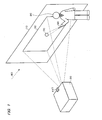
- FIG. 1 A schematic illustrative view shown in Fig. 1 is of a presentation system that makes use of a laser pointer 50, in accordance with an example of this embodiment of the present invention.
- a projector 20 that is provided substantially facing a screen 10 projects an image for a predetermined presentation.
- a presenter 30 gives a presentation to an audience, while using a light spot 70 projected from the laser pointer 50 to point at a desired position of an image in an image display region 12, which is a image-displayed area on the screen.
- the way in which images on the image display region 12 are seen will vary greatly, depending on factors such as the type of the screen 10 and ambient light 80.
- the same white when the same white is displayed, for example, it could seem to be white with a yellow cast or white with a blue cast, depending on the type of the screen 10. Even when the same white is displayed, it could seem to be a bright white or a dull white if the ambient light 80 differs.
- the projector 20 has become smaller and easy to transport. For that reason, it has become possible to perform presentations at a client's location, by way of example, but it is difficult to adjust colors to match the environment at the client's location and the manual adjustment of colors at the client's location takes too much time.
- FIG. 2 A functional block diagram of the image processing section within a prior-art projector is shown in Fig. 2.
- This prior-art projector inputs an R1 signal, a G1 signal, and a B1 signal (which for RGB signals in analog format, sent from a PC or the like) to an A/D conversion section 110, and uses a projector image processing section 100 to perform color modification on an R2 signal, a G2 signal, and a B2 signal which have been converted into digital form by the A/D conversion section 110.
- a D/A conversion section 180 converts an R3 signal, a G3 signal, and a B3 signal, which have been subjected to the color modification of the projector image processing section 100, into analog form and outputs them as an R4 signal, a G4 signal, and a B4 signal.
- a light valve (L/V) drive section 190 drives liquid-crystal light bulbs to display an image, based on the R4 signal G4 signal, and B4 signal.
- the projector image processing section 100 which is controlled by a CPU 200, comprises a projector color conversion section 120 and a profile management section 130.
- the projector color conversion section 120 converts the RGB digital signals (the R2 signal, G2 signal, and B2 signal) into RGB digital signals for projector output (the R3 signal, G3 signal, and B3 signal), based on a projector input-output profile that is managed by the profile management section 130.
- profile in this case refers to characteristic data.
- the prior-art projector can only perform color modification based on an input-output profile that indicates input-output characteristics that are specific to that particular projector, so no consideration is paid to the visual environment in which the image is projected and displayed.
- the way in which colors are seen is determined by three factors: light, the reflection or transmission of light by objects, and vision.
- This embodiment of the present invention implements an image display system that can reproduce an image with the same visual appearance, by determining the visual environment of light and the reflection or transmission of light by objects, irrespective of the environment in which it is applied.
- the device is provided with a colored-light sensor 417 that functions as visual environment detection means for determining the visual environment, as shown in Fig. 1, and environmental information from the colored-light sensor 417 is input to the projector 20.
- the colored-light sensor 417 measures colored-light information (more specifically, information indicating xyY colors and brightness) of the image display region 12 within the screen 10.
- the projector 20 is provided with color control processing means that stores and manages brightness correction information, for correcting the brightness of the image based on this environmental information, and color correction information, for correcting the colors of the image based on this environmental information, and correction means that corrects the image information for displaying the image, based on the environmental information, the brightness correction information, and the color correction information.
- FIG. 3 A functional block diagram of the image processing section within the projector 20 in accordance with an example of this embodiment of the invention is shown in Fig. 3.
- the image processing section comprises an input signal processing section 401 to which RGB signals are input, a color control processing section 420, a calibration section 430 that functions as correction means, an output signal processing section 405, and an L/V drive section 406.
- the input signal processing section 401 comprises an A/D conversion section 440 that converts the R1, G1, and B1 analog image signals into the R2, G2, and B2 digital image signals.
- the color control processing section 420 comprises a one-dimensional look-up table (1D-LUT) 402 for input signal processing, a three-dimensional look-up table (3D-LUT) storage section 403 that is used in correcting the color information, and a 1D-LUT storage section 404 that is used in correcting the brightness information.
- (1D-LUT) 402 for input signal processing
- 3D-LUT three-dimensional look-up table
- 3D-LUT three-dimensional look-up table
- 1D-LUT storage section 404 that is used in correcting the brightness information.
- a gamma table and color balance table are stored as part of the brightness correction information in the 1D-LUT storage sections 402 and 404.
- a color gamut correction table and a color temperature correction table are stored as part of the color correction information in the 3D-LUT storage section 403.
- color control is done with a 1D-LUT and brightness correction is done by determining what potential is used when sampling the input signal.
- brightness correction is performed by a 1D-LUT that can manipulate a grayscale characteristic.
- color correction is done with a 3D-LUT, to ensure appropriate color compression or color expansion for each color when it comes to matching other reproducible color gamuts by color control.
- brightness and color can be corrected separately, based on environmental information relating to brightness and environmental information relating to color, making it possible to perform each type of correction more precisely.
- the calibration section 430 comprises a calibration image presentation section 407 which inputs image signals for calibration (correction) to the input signal processing section 401, a color conversion section 408 which converts colors for conversion (stored in the 3D-LUT storage section 403) from the RGB color system into the XYZ color system, and an environmental correction processing section 410 which performs color and brightness correction, based on environmental information that is input from the colored-light sensor 417.
- RGB system results in device-dependent colors that vary with the input-output device, such as a projector, but the XYZ system results in non-device-dependent colors.
- the calibration section 430 comprises a Gamut information management section 412 and a chromaticity correction coefficient processing section 411.
- the Gamut information management section 412 manages the color gamut information of the image to be depicted.
- the color gamut information is supplied to the chromaticity correction coefficient processing section 411 and used in the derivation of chromaticity correction coefficients ⁇ .
- the chromaticity correction coefficient processing section 411 draws a plurality of similarly-shaped triangles of the reproducible color gamut, based on the RGB colors from the Gamut information management section 412.
- the chromaticity correction coefficient processing section 411 derives chromaticity correction coefficients (such as ⁇ (x1,y1 , Y1)) that are based on color information (such as x1,y1 , Y1) from the environmental correction processing section 410.
- RGBW where W means white (or gray)
- the chromaticity correction coefficient processing section 411 obtains chromaticity correction coefficients ( ⁇ (x1, y1, Y1)) relating to the color information (x1, y1, Y1) that is input from the input signal processing section 401, and outputs those chromaticity correction coefficients to the environmental correction processing section 410.
- the environmental correction processing section 410 also inputs environmental information from the colored-light sensor 417.
- the colored-light sensor 417 functions as a visual environment detection means that determines the visual environment.
- the colored-light sensor 417 could be one or a combination of several different devices, such as a luminance sensor that measures the luminance value of the image-displayed area, a colored-light sensor that measures the RGB values or XYZ values of the image-displayed area, or a chromaticity sensor that measures the chromaticity values of the image-displayed area.
- the environmental correction processing section 410 could also input a plurality of items of environmental information from the colored-light sensor 417. In such a case, the environmental correction processing section 410 would have to perform weighting in accordance with the input environmental information (such as weighting of luminance, color temperature, and color information).
- the environmental correction processing section 410 is provided with an environmental information collecting section 450 that collects a plurality of items of environmental information all together.
- the environmental information collecting section 450 performs predetermined processing on a plurality of items of environmental information to obtain a single of environmental information.
- a and b are the previously described weighting coefficients.
- weighting can be done in a collected manner to derive coordinated correction requests ⁇ x , ⁇ y , and ⁇ Y that are necessary for correcting for various environmental influences.
- the subsequent circuitry can perform the necessary corrections in a simple manner, by using ⁇ x , ⁇ y , and ⁇ Y .
- ⁇ x , ⁇ y , and ⁇ Y in this case are derived from a comparison with environmental information for an ideal state.
- the environmental correction processing section 410 performs color correction by using the color information ( ⁇ x , ⁇ y ) from within the collected environmental information.
- the environmental correction processing section 410 performs the processing described below upon color information (such as X1, Y1, and Z1) from a 3D-LUT storage section 409, in order to overwrite corresponding colors of the 3D-LUT storage section 403.
- the environmental correction processing section 410 then outputs color information (x1, y1, Y1) to the chromaticity correction coefficient processing section 411 and inputs chromaticity correction information ( ⁇ (x1, y1, Y1)) from the chromaticity correction coefficient processing section 411.
- the environmental correction processing section 410 outputs the thus-obtained tri-stimulus values (X'1, Y'1, Z'1) to a post-correction 3D-LUT storage section 414.
- the color conversion section 408 converts the (X'1, Y'1, Z'1) values in the post-correction 3D-LUT storage section 414 into (R'1, G'1, B'1) values, then outputs the converted (R'1, G'1, B'1) values to the 3D-LUT storage section 403.
- This brightness correction is mainly done by correcting the ⁇ values in each 1D-LUT stored in the 1D-LUT storage section 402 and the 1D-LUT storage section 404, by ⁇ correction section 413.
- the ⁇ correction section 413 performs ⁇ correction processing based on ⁇ Y from the environmental correction processing section 410, to convert ⁇ 1 of the 1D-LUT storage section 402 into ⁇ 1' and ⁇ 2 of the 1D-LUT storage section 404 into ⁇ 2'.
- the output signal processing section 405 inputs image signals (R5, G5, and B5) that have been adjusted by using the look-up tables (LUTs) that have been subjected to brightness correction by the 1D-LUT storage sections 402 and 404 and color correction by the 3D-LUT storage section 403.
- LUTs look-up tables
- the output signal processing section 405 uses a D/A conversion section 441 to convert the digital image signals (R5, G5, and B5) into analog image signals (R6, G6, and B6), then outputs the converted analog image signals to the L/V drive section 406.
- the L/V drive section 406 uses those analog image signals to drive liquid-crystal light bulbs to regulate the image projected from the projector 20.
- the way in which the image is seen in the image display region 12 of the screen 10 can be adjusted as appropriate by adjusting the image projected by the projector 20.
- This embodiment of the present invention therefore ensures that the projector 20 takes the visual environment into consideration when projecting and displaying an image.
- This embodiment of the present invention therefore enables the reproduction of substantially the same colors within a short time, in a plurality of different locations.
- the projector 20 can also boost the output of lower-range grayscale and correct the brightness of the reproduced colors by using a 1D-LUT that enables manipulation of the grayscale characteristic during the brightness correction.
- the projector 20 can also apply color compression and color expansion independently for each color, by using a 3D-LUT for the color correction.
- the projector 20 can apply brightness correction and color correction separately, based on environmental information relating to brightness and environmental information relating to color, thus enabling it to apply both types of correction more precisely.
- the input signal processing section 401 could be implemented by using an A/D converter or the like
- the color control processing section 420 could be implemented by using RAM or a CPU or the like
- the output signal processing section 405 could be implemented by using a D/A converter or the like
- the L/V drive section 406 could be implemented by using a liquid-crystal light bulb driver or the like
- the calibration section 430 could be implemented by using an image processing circuit or the like.
- these components could be implemented by hardware such as circuitry, or by software such as drivers.
- the functions of these components could also be implemented by the reading of information from an information storage medium 500.
- Means such as a CD-ROM, DVD-ROM, ROM, RAM, or hard disk can be used as the information storage medium 500, and either a direct method or an indirect method could be used for reading that information.
- the LUTs stored in the previously described 1D-LUT storage sections 402 and 404 could provide values that are scattered, such as in a mapping table form, or they could provide continuous values, such as those derived from functions.
- substantially continuous values can be obtained by interpolation using a method such as Lagrange interpolation or linear interpolation.
- the colored-light sensor 417 was used as the visual environment detection means by way of example, but an input means that inputs at least some part of the environmental information (such as the presence/absence of external light, the illumination type, or the screen type) or an image display means that displays an image for prompting the input of such details could be used therefor. Both the colored-light sensor 417 and means for displaying a screentype input image for acquiring information such as the screen type could be used together as the visual environment detection means.
- the visual environment determined by the visual environment detection means applies to factors such as ambient light (such as artificial light or natural light) and the object on which the image is displayed (such as a display, wall surface, or screen).
- this embodiment of the present invention makes it possible to apply more appropriate image correction by obtaining information on a component that is not much considered in the prior art (i.e., the screen), thus enabling the reproduction of more uniform image colors.
- the screen 10 described above is of a reflective type, but it could equally well be of a transparent type. If the screen is of a transparent type, a sensor that scans the screen directly could be used as the colored-light sensor.
- the present invention can also be applied to presentations done by displaying images by a display means other than a projection means such as the previously described projector.
- a display means other than a projection means such as the previously described projector.
- a projector using a digital micromirror device (DMD), a cathode ray tube (CRT), a plasma display panel (PDP), a field emission display (FED) device, an electroluminescence (EL) device, or a direct-vision type of liquid crystal display device could be used as such a display means.
- DMD digital micromirror device
- CRT cathode ray tube
- PDP plasma display panel
- FED field emission display
- EL electroluminescence
- EL electroluminescence
- direct-vision type of liquid crystal display device could be used as such a display means.
- DMD is a trademark registered to Texas Instruments Inc. of the USA.
- the present invention would also be effective when displaying images in applications that are not presentations, such as in meetings, for medical treatment, in the design or fashion world, in business activities, and in education, as well as for general-purpose image displays such as movies, TV, video, and games.
- the A/D conversion section 440 is not necessary when the input signal (R1, G1, B1) is in digital form, and the D/A conversion section is also not necessary when the output signal (R6, G6, B6) is digital form. This can be done as necessary in accordance with the input devices and output devices that are used.
- the functions of the previously described image processing section of the projector 20 could be implemented by a simple image display device (such as the projector 20), or they could be implemented by being distributed between a plurality of processing devices (such as processing that is distributed between the projector 20 and a PC).
- information in xyY (or Yxy) form is used as color information comprising brightness information, but it could equally well be in another format such as Lab, Luv, or LCh.
- the above described environmental information could also be values that express color and brightness in a form such as xyY, but it could also be color and brightness correction amounts in a form such as ⁇ x ⁇ y ⁇ Y .
Landscapes
- Engineering & Computer Science (AREA)
- Multimedia (AREA)
- Signal Processing (AREA)
- Physics & Mathematics (AREA)
- Computer Hardware Design (AREA)
- General Physics & Mathematics (AREA)
- Theoretical Computer Science (AREA)
- Controls And Circuits For Display Device (AREA)
- Control Of Indicators Other Than Cathode Ray Tubes (AREA)
- Liquid Crystal Display Device Control (AREA)
- Processing Of Color Television Signals (AREA)
- Color Image Communication Systems (AREA)
- Digital Computer Display Output (AREA)
- Facsimile Image Signal Circuits (AREA)
- Transforming Electric Information Into Light Information (AREA)
- Image Processing (AREA)
Priority Applications (2)
| Application Number | Priority Date | Filing Date | Title |
|---|---|---|---|
| EP10184751.5A EP2302919B1 (de) | 2000-07-31 | 2001-07-31 | Projektor |
| EP10184709A EP2302918A1 (de) | 2000-07-31 | 2001-07-31 | Projektor |
Applications Claiming Priority (2)
| Application Number | Priority Date | Filing Date | Title |
|---|---|---|---|
| JP2000230950A JP3632574B2 (ja) | 2000-07-31 | 2000-07-31 | 環境適応型の画像表示システムおよび情報記憶媒体 |
| JP2000230950 | 2000-07-31 |
Related Child Applications (1)
| Application Number | Title | Priority Date | Filing Date |
|---|---|---|---|
| EP10184751.5A Division EP2302919B1 (de) | 2000-07-31 | 2001-07-31 | Projektor |
Publications (2)
| Publication Number | Publication Date |
|---|---|
| EP1178680A2 true EP1178680A2 (de) | 2002-02-06 |
| EP1178680A3 EP1178680A3 (de) | 2003-04-16 |
Family
ID=18723842
Family Applications (3)
| Application Number | Title | Priority Date | Filing Date |
|---|---|---|---|
| EP10184709A Withdrawn EP2302918A1 (de) | 2000-07-31 | 2001-07-31 | Projektor |
| EP10184751.5A Expired - Lifetime EP2302919B1 (de) | 2000-07-31 | 2001-07-31 | Projektor |
| EP20010118454 Withdrawn EP1178680A3 (de) | 2000-07-31 | 2001-07-31 | Umgebungsnachgiebiges Bildanzeigesystem und Informationsbewahrungsmedium |
Family Applications Before (2)
| Application Number | Title | Priority Date | Filing Date |
|---|---|---|---|
| EP10184709A Withdrawn EP2302918A1 (de) | 2000-07-31 | 2001-07-31 | Projektor |
| EP10184751.5A Expired - Lifetime EP2302919B1 (de) | 2000-07-31 | 2001-07-31 | Projektor |
Country Status (4)
| Country | Link |
|---|---|
| US (1) | US6894697B2 (de) |
| EP (3) | EP2302918A1 (de) |
| JP (1) | JP3632574B2 (de) |
| CN (1) | CN100401249C (de) |
Cited By (8)
| Publication number | Priority date | Publication date | Assignee | Title |
|---|---|---|---|---|
| WO2002097784A1 (fr) * | 2001-05-31 | 2002-12-05 | Seiko Epson Corporation | Systeme de visualisation d'images, projecteur, support d'informations, et procede de traitement d'images |
| WO2003079327A1 (fr) * | 2002-03-18 | 2003-09-25 | Seiko Epson Corporation | Appareil d'affichage d'image, procede de traitement d'image, programme et support d'enregistrement |
| EP1429551A3 (de) * | 2002-12-12 | 2006-02-08 | Samsung Electronics Co., Ltd. | Verfahren und Vorrichtung zur Erzeugung von Beleuchtungseigenschaftendaten des Bildschirmsumgebungs, und Verfahren und Vorrichtung zur Kompensierung von Farbveränderungen welches dieses Verfahren und Vorrichtung benutzt |
| US7011413B2 (en) | 2002-05-09 | 2006-03-14 | Seiko Epson Corporation | Image processing system, projector, program, information storage medium, and image processing method |
| US7170634B2 (en) | 2001-03-06 | 2007-01-30 | Seiko Epson Corporation | Picture display system, picture data processing method, and program for performing color correction of output pictures |
| EP1830584A1 (de) * | 2003-10-21 | 2007-09-05 | Barco N.V. | Verfahren und Vorrichtung zur Durchführung einer stereoskopischen Bildanzeige auf der Basis von farbselektiven Filtern |
| DE102008019726A1 (de) * | 2008-04-18 | 2009-10-22 | Zentrum für Bild- und Signalverarbeitung e.V. | Verfahren und Vorrichtung zur Farbkalibrierung von Projektoren |
| EP1942680A3 (de) * | 2007-01-04 | 2012-05-02 | Samsung Electronics Co., Ltd. | Vorrichtung und Verfahren für eine adaptive Umgebungslichtfarbkorrektur |
Families Citing this family (37)
| Publication number | Priority date | Publication date | Assignee | Title |
|---|---|---|---|---|
| US7595811B2 (en) | 2001-07-26 | 2009-09-29 | Seiko Epson Corporation | Environment-complaint image display system, projector, and program |
| JP2003323610A (ja) | 2002-03-01 | 2003-11-14 | Nec Corp | プロジェクタの色補正方法および色補正装置 |
| US7038647B2 (en) | 2002-03-25 | 2006-05-02 | Sharp Kabushiki Kaisha | Liquid crystal display apparatus |
| JP3894302B2 (ja) | 2002-03-25 | 2007-03-22 | セイコーエプソン株式会社 | 画像表示システム、画像処理方法、プログラムおよび情報記憶媒体 |
| JP4445693B2 (ja) | 2002-05-17 | 2010-04-07 | 日本電気株式会社 | プロジェクタの投射面色補正方法、プロジェクタの投射面色補正システムおよびプロジェクタの投射面色補正用プログラム |
| KR20030090849A (ko) | 2002-05-22 | 2003-12-01 | 엘지전자 주식회사 | 영상 디스플레이 장치 |
| JP2004077748A (ja) * | 2002-08-16 | 2004-03-11 | Nec Viewtechnology Ltd | プロジェクタ装置、プロジェクタ装置のリモートコントローラ、画像投射方法および画像補正方法 |
| KR20040051325A (ko) * | 2002-12-12 | 2004-06-18 | 엘지전자 주식회사 | 프로젝션 티브이의 감마 보정 장치 및 방법 |
| JP4120841B2 (ja) | 2003-12-10 | 2008-07-16 | 日本電気株式会社 | プロジェクタの色補正方法 |
| KR100565810B1 (ko) | 2004-06-16 | 2006-03-29 | 삼성전자주식회사 | 색신호 처리장치 및 방법 |
| KR100676817B1 (ko) * | 2004-11-17 | 2007-01-31 | 삼성전자주식회사 | 디스플레이장치의 감마조정방법 및 감마조정시스템 |
| KR100621853B1 (ko) * | 2004-11-23 | 2006-09-19 | 삼성전자주식회사 | 개량된 색상 이미지 표시 장치 및 방법을 가지는 이동통신단말기 |
| KR100640063B1 (ko) * | 2005-02-18 | 2006-10-31 | 삼성전자주식회사 | 외부조도를 고려한 영상향상방법 및 장치 |
| CN100468517C (zh) * | 2005-03-31 | 2009-03-11 | 华硕电脑股份有限公司 | 影视信号的处理方法及其处理装置 |
| KR101133572B1 (ko) | 2005-06-21 | 2012-04-05 | 삼성전자주식회사 | 다수의 색재현 범위를 갖는 색재현 장치 및 그 색신호처리방법 |
| JP5055760B2 (ja) * | 2005-12-16 | 2012-10-24 | セイコーエプソン株式会社 | プロジェクタ |
| TWI338515B (en) * | 2006-02-20 | 2011-03-01 | Mstar Semiconductor Inc | Color calibration device and system and method for use therewith |
| KR20080014495A (ko) * | 2006-08-11 | 2008-02-14 | 삼성전자주식회사 | 프로젝터의 영상 보정기능을 제공하는 장치 및 방법 |
| JP4957162B2 (ja) | 2006-10-06 | 2012-06-20 | セイコーエプソン株式会社 | 投写表示装置および投写表示方法 |
| JP2008098849A (ja) * | 2006-10-10 | 2008-04-24 | Sharp Corp | 映像情報の色空間の変換を行なう電子機器 |
| JP2009199090A (ja) * | 2007-06-29 | 2009-09-03 | Sharp Corp | 画像表示装置 |
| JP4382132B2 (ja) * | 2007-06-29 | 2009-12-09 | シャープ株式会社 | 画像表示装置 |
| JP5320865B2 (ja) * | 2008-07-04 | 2013-10-23 | セイコーエプソン株式会社 | プロジェクタおよびプロジェクタの制御方法 |
| JP5169652B2 (ja) * | 2008-09-08 | 2013-03-27 | セイコーエプソン株式会社 | 画像処理装置、画像表示装置、画像処理方法及び画像表示方法 |
| US8654140B2 (en) * | 2008-12-26 | 2014-02-18 | Seiko Epson Corporation | Image processor, image display device, and image processing method |
| US8780143B2 (en) * | 2009-02-19 | 2014-07-15 | Samsung Electronics Co., Ltd | Display method and apparatus for controlling brightness of projector light source |
| KR101600495B1 (ko) * | 2010-01-08 | 2016-03-08 | 삼성디스플레이 주식회사 | 신호 처리 장치 및 신호 처리 방법 |
| JP5534825B2 (ja) * | 2010-01-19 | 2014-07-02 | キヤノン株式会社 | 映像処理装置及び色温度補正方法 |
| US8547445B1 (en) * | 2010-02-17 | 2013-10-01 | Ambarella, Inc. | Camera using combined color processing in lookup |
| US8531549B1 (en) | 2010-02-25 | 2013-09-10 | Ambarella, Inc. | Camera that uses YUV to YUV table-based color correction for processing digital images |
| WO2012073338A1 (ja) * | 2010-11-30 | 2012-06-07 | Necディスプレイソリューションズ株式会社 | 表示装置、表示装置の色補正方法 |
| US10319268B2 (en) * | 2016-06-24 | 2019-06-11 | Nanosys, Inc. | Ambient light color compensating device |
| CN106408540B (zh) * | 2016-09-27 | 2020-11-06 | 新奥特(北京)视频技术有限公司 | 一种基于3d lut表的外插处理方法和装置 |
| CN112599073B (zh) * | 2020-03-27 | 2022-04-08 | 西安诺瓦星云科技股份有限公司 | 显示屏色彩管理方法、装置和系统 |
| CN113707074B (zh) * | 2020-05-20 | 2022-11-18 | 西安诺瓦星云科技股份有限公司 | 显示屏信息管理方法 |
| CN112885280A (zh) * | 2021-01-22 | 2021-06-01 | 重庆惠科金渝光电科技有限公司 | 一种显示装置的驱动方法、装置、显示设备及存储介质 |
| CN117711287A (zh) * | 2022-09-01 | 2024-03-15 | 华为技术有限公司 | 显示方法和装置 |
Family Cites Families (29)
| Publication number | Priority date | Publication date | Assignee | Title |
|---|---|---|---|---|
| JPS5966280A (ja) | 1982-10-07 | 1984-04-14 | Sony Corp | テレビ受像機 |
| JPS63177193A (ja) | 1987-01-19 | 1988-07-21 | 株式会社日立製作所 | デイスプレイ装置 |
| JP2973477B2 (ja) | 1990-06-20 | 1999-11-08 | ソニー株式会社 | 補正回路付プロジェクタ |
| JP2798800B2 (ja) | 1990-09-18 | 1998-09-17 | 三洋電機株式会社 | テレビジョン受像機の調整方法 |
| KR930005599B1 (ko) | 1991-05-16 | 1993-06-23 | 삼성전자 주식회사 | 칼라텔레비젼의 화면 조정 회로 및 방법 |
| JP2548470B2 (ja) | 1991-10-04 | 1996-10-30 | 国際電気株式会社 | 表示器の輝度特性制御装置 |
| JP3116472B2 (ja) * | 1991-11-18 | 2000-12-11 | ソニー株式会社 | ホワイト・バランス調整方法 |
| JPH06178244A (ja) | 1992-12-11 | 1994-06-24 | Matsushita Electric Ind Co Ltd | 投写型ディスプレイの画像処理方法およびその装置 |
| US5760843A (en) | 1993-01-19 | 1998-06-02 | Matsushita Electric Industrial Co., Ltd. | Method and apparatus for contrast processing a video signal including brightness level compensation |
| AU5856194A (en) | 1993-02-05 | 1994-08-29 | Barath, Ludwig | Environment-dependent automatic luminance control for display scrreens |
| JPH0795558A (ja) | 1993-09-24 | 1995-04-07 | Matsushita Electric Works Ltd | 画像監視装置 |
| US5499040A (en) | 1994-06-27 | 1996-03-12 | Radius Inc. | Method and apparatus for display calibration and control |
| KR0177937B1 (ko) | 1994-08-04 | 1999-05-01 | 구자홍 | 영상표시기기의 영상 자동 보정 장치와 방법 |
| US5561459A (en) * | 1994-09-30 | 1996-10-01 | Apple Computer, Inc. | Automatic profile generation for a self-calibrating color display |
| JPH0918806A (ja) | 1995-06-30 | 1997-01-17 | Fuji Photo Film Co Ltd | 画像表示方法および装置 |
| JPH09107484A (ja) | 1995-10-12 | 1997-04-22 | Ricoh Co Ltd | 色補正装置、色管理方法および装置 |
| JPH09149337A (ja) | 1995-10-24 | 1997-06-06 | Chishu Denno Kofun Yugenkoshi | ディスプレイで輝度とコントラストを自動制御するシステムと方法 |
| JPH1065930A (ja) | 1996-08-19 | 1998-03-06 | Fuji Xerox Co Ltd | カラー画像処理方法およびカラー画像処理装置 |
| JPH1062865A (ja) | 1996-08-20 | 1998-03-06 | Hitachi Ltd | 表示装置及び表示方法 |
| JP3658104B2 (ja) | 1996-10-01 | 2005-06-08 | キヤノン株式会社 | 環境照明光特定装置 |
| EP0863677B1 (de) | 1997-03-08 | 2004-09-08 | Lg Electronics Inc. | Verfahren zur Beurteilung des Umgebungslichts und deren Verwendung in einer Steuervorrichtung zur Videokompensation |
| JPH1141478A (ja) | 1997-07-24 | 1999-02-12 | Canon Inc | 画像処理方法、装置および記録媒体 |
| JP4076248B2 (ja) | 1997-09-09 | 2008-04-16 | オリンパス株式会社 | 色再現装置 |
| GB2335326B (en) | 1997-10-31 | 2002-04-17 | Sony Corp | Image processing apparatus and method and providing medium. |
| JPH11175048A (ja) | 1997-12-15 | 1999-07-02 | Fuji Xerox Co Ltd | カラー画像変換係数算出方法およびカラー画像変換方法 |
| JP3804254B2 (ja) * | 1998-02-16 | 2006-08-02 | セイコーエプソン株式会社 | 液晶プロジェクション装置 |
| KR100299759B1 (ko) | 1998-06-29 | 2001-10-27 | 구자홍 | 영상표시기기의 화면 상태 자동 조정 장치와 방법 |
| US6456339B1 (en) * | 1998-07-31 | 2002-09-24 | Massachusetts Institute Of Technology | Super-resolution display |
| JP4292612B2 (ja) | 1999-02-09 | 2009-07-08 | 東洋紡績株式会社 | 表面抵抗測定装置 |
-
2000
- 2000-07-31 JP JP2000230950A patent/JP3632574B2/ja not_active Expired - Fee Related
-
2001
- 2001-07-30 US US09/916,677 patent/US6894697B2/en not_active Expired - Lifetime
- 2001-07-31 CN CNB011328975A patent/CN100401249C/zh not_active Expired - Fee Related
- 2001-07-31 EP EP10184709A patent/EP2302918A1/de not_active Withdrawn
- 2001-07-31 EP EP10184751.5A patent/EP2302919B1/de not_active Expired - Lifetime
- 2001-07-31 EP EP20010118454 patent/EP1178680A3/de not_active Withdrawn
Cited By (18)
| Publication number | Priority date | Publication date | Assignee | Title |
|---|---|---|---|---|
| US7170634B2 (en) | 2001-03-06 | 2007-01-30 | Seiko Epson Corporation | Picture display system, picture data processing method, and program for performing color correction of output pictures |
| WO2002097784A1 (fr) * | 2001-05-31 | 2002-12-05 | Seiko Epson Corporation | Systeme de visualisation d'images, projecteur, support d'informations, et procede de traitement d'images |
| WO2003079327A1 (fr) * | 2002-03-18 | 2003-09-25 | Seiko Epson Corporation | Appareil d'affichage d'image, procede de traitement d'image, programme et support d'enregistrement |
| US7079155B2 (en) | 2002-03-18 | 2006-07-18 | Seiko Epson Corporation | Image display device, image processing method, program, and storage medium |
| CN100341045C (zh) * | 2002-03-18 | 2007-10-03 | 精工爱普生株式会社 | 图像显示装置和图像处理方法 |
| US7011413B2 (en) | 2002-05-09 | 2006-03-14 | Seiko Epson Corporation | Image processing system, projector, program, information storage medium, and image processing method |
| EP1363462A3 (de) * | 2002-05-09 | 2008-04-23 | Seiko Epson Corporation | Bildverarbeitungssystem, Bildprojektor, Informationsspeichermedium und Bildverarbeitungsverfahren |
| US7616214B2 (en) | 2002-12-12 | 2009-11-10 | Samsung Electronics Co., Ltd. | Method and apparatus for generating characteristic data of illumination around image display device |
| EP1429551A3 (de) * | 2002-12-12 | 2006-02-08 | Samsung Electronics Co., Ltd. | Verfahren und Vorrichtung zur Erzeugung von Beleuchtungseigenschaftendaten des Bildschirmsumgebungs, und Verfahren und Vorrichtung zur Kompensierung von Farbveränderungen welches dieses Verfahren und Vorrichtung benutzt |
| US7872658B2 (en) | 2002-12-12 | 2011-01-18 | Samsung Electronics Co., Ltd. | Method and apparatus for generating characteristic data of illumination around image display device |
| EP1843602A3 (de) * | 2002-12-12 | 2007-12-05 | Samsung Electronics Co., Ltd. | Verfahren und Vorrichtung zur Erzeugung von Beleuchtungseigenschaften des Bildschirmsumgebungs, und Verfahren und Vorrichtung zur Kompensierung von Farbveränderungen welches dieses Verfahren und Vorrichtung benutzt |
| EP1830585A3 (de) * | 2003-10-21 | 2007-11-21 | Barco N.V. | Verfahren und Vorrichtung zur Durchführung einer stereoskopischen Bildanzeige auf der Basis von farbselektiven Filtern |
| EP1676449B1 (de) * | 2003-10-21 | 2008-11-26 | Barco N.V. | Verfahren und einrichtung zur durchführung einer stereoskopischen bildanzeige auf der basis von farbselektiven filtern |
| US7832869B2 (en) | 2003-10-21 | 2010-11-16 | Barco N.V. | Method and device for performing stereoscopic image display based on color selective filters |
| EP1830584A1 (de) * | 2003-10-21 | 2007-09-05 | Barco N.V. | Verfahren und Vorrichtung zur Durchführung einer stereoskopischen Bildanzeige auf der Basis von farbselektiven Filtern |
| EP1942680A3 (de) * | 2007-01-04 | 2012-05-02 | Samsung Electronics Co., Ltd. | Vorrichtung und Verfahren für eine adaptive Umgebungslichtfarbkorrektur |
| US8243210B2 (en) | 2007-01-04 | 2012-08-14 | Samsung Electronics Co., Ltd. | Apparatus and method for ambient light adaptive color correction |
| DE102008019726A1 (de) * | 2008-04-18 | 2009-10-22 | Zentrum für Bild- und Signalverarbeitung e.V. | Verfahren und Vorrichtung zur Farbkalibrierung von Projektoren |
Also Published As
| Publication number | Publication date |
|---|---|
| EP2302918A1 (de) | 2011-03-30 |
| US6894697B2 (en) | 2005-05-17 |
| CN100401249C (zh) | 2008-07-09 |
| EP2302919B1 (de) | 2016-09-28 |
| JP2002041016A (ja) | 2002-02-08 |
| JP3632574B2 (ja) | 2005-03-23 |
| EP1178680A3 (de) | 2003-04-16 |
| US20020048084A1 (en) | 2002-04-25 |
| CN1336584A (zh) | 2002-02-20 |
| EP2302919A1 (de) | 2011-03-30 |
Similar Documents
| Publication | Publication Date | Title |
|---|---|---|
| US6894697B2 (en) | Environment-compliant image display system and program | |
| US6847374B2 (en) | Environment-compliant image display system and program | |
| US7986332B2 (en) | Environment-compliant image display system, projector, and program | |
| US6765585B2 (en) | Image display system, image processing method, and program | |
| JP3719411B2 (ja) | 画像表示システム、プロジェクタ、プログラム、情報記憶媒体および画像処理方法 | |
| US8243210B2 (en) | Apparatus and method for ambient light adaptive color correction | |
| JP4110408B2 (ja) | 画像表示システム、プロジェクタ、画像処理方法および情報記憶媒体 | |
| EP1370092A1 (de) | Sich an die umgebung anpassendes anzeigesystem, informationsspeichermedium und bildverarbeitungsverfahren | |
| JP3707350B2 (ja) | 画像表示システム、プロジェクタ、画像処理方法および情報記憶媒体 | |
| US6899431B2 (en) | Image processing system, projector, information storage medium, and image processing method | |
| JP2002125125A (ja) | 環境適応型の画像表示システム、プログラムおよび情報記憶媒体 | |
| EP1315142B1 (de) | An Umgebung angepasstes Bildanzeigesystem und Bildverarbeitungssystem | |
| JP4743424B2 (ja) | 画像表示システム、プロジェクタ、プログラムおよび情報記憶媒体 | |
| JP4150876B2 (ja) | 画像表示システム、画像処理方法、プログラムおよび情報記憶媒体 | |
| JP4164659B2 (ja) | 画像表示システムおよび画像表示方法 |
Legal Events
| Date | Code | Title | Description |
|---|---|---|---|
| PUAI | Public reference made under article 153(3) epc to a published international application that has entered the european phase |
Free format text: ORIGINAL CODE: 0009012 |
|
| AK | Designated contracting states |
Kind code of ref document: A2 Designated state(s): AT BE CH CY DE DK ES FI FR GB GR IE IT LI LU MC NL PT SE TR |
|
| AX | Request for extension of the european patent |
Free format text: AL;LT;LV;MK;RO;SI |
|
| PUAL | Search report despatched |
Free format text: ORIGINAL CODE: 0009013 |
|
| AK | Designated contracting states |
Designated state(s): AT BE CH CY DE DK ES FI FR GB GR IE IT LI LU MC NL PT SE TR |
|
| AX | Request for extension of the european patent |
Extension state: AL LT LV MK RO SI |
|
| 17P | Request for examination filed |
Effective date: 20030911 |
|
| AKX | Designation fees paid |
Designated state(s): DE FR GB |
|
| 17Q | First examination report despatched |
Effective date: 20080623 |
|
| STAA | Information on the status of an ep patent application or granted ep patent |
Free format text: STATUS: THE APPLICATION IS DEEMED TO BE WITHDRAWN |
|
| 18D | Application deemed to be withdrawn |
Effective date: 20160202 |