EP1168084A2 - Antriebsmechanismus und damit versehener Belichtungsapparat - Google Patents
Antriebsmechanismus und damit versehener Belichtungsapparat Download PDFInfo
- Publication number
- EP1168084A2 EP1168084A2 EP01305451A EP01305451A EP1168084A2 EP 1168084 A2 EP1168084 A2 EP 1168084A2 EP 01305451 A EP01305451 A EP 01305451A EP 01305451 A EP01305451 A EP 01305451A EP 1168084 A2 EP1168084 A2 EP 1168084A2
- Authority
- EP
- European Patent Office
- Prior art keywords
- stage
- movable
- stator
- stators
- exposure
- Prior art date
- Legal status (The legal status is an assumption and is not a legal conclusion. Google has not performed a legal analysis and makes no representation as to the accuracy of the status listed.)
- Granted
Links
Images


Classifications
-
- G—PHYSICS
- G03—PHOTOGRAPHY; CINEMATOGRAPHY; ANALOGOUS TECHNIQUES USING WAVES OTHER THAN OPTICAL WAVES; ELECTROGRAPHY; HOLOGRAPHY
- G03F—PHOTOMECHANICAL PRODUCTION OF TEXTURED OR PATTERNED SURFACES, e.g. FOR PRINTING, FOR PROCESSING OF SEMICONDUCTOR DEVICES; MATERIALS THEREFOR; ORIGINALS THEREFOR; APPARATUS SPECIALLY ADAPTED THEREFOR
- G03F7/00—Photomechanical, e.g. photolithographic, production of textured or patterned surfaces, e.g. printing surfaces; Materials therefor, e.g. comprising photoresists; Apparatus specially adapted therefor
- G03F7/70—Microphotolithographic exposure; Apparatus therefor
- G03F7/70691—Handling of masks or workpieces
-
- H10P76/00—
-
- G—PHYSICS
- G03—PHOTOGRAPHY; CINEMATOGRAPHY; ANALOGOUS TECHNIQUES USING WAVES OTHER THAN OPTICAL WAVES; ELECTROGRAPHY; HOLOGRAPHY
- G03F—PHOTOMECHANICAL PRODUCTION OF TEXTURED OR PATTERNED SURFACES, e.g. FOR PRINTING, FOR PROCESSING OF SEMICONDUCTOR DEVICES; MATERIALS THEREFOR; ORIGINALS THEREFOR; APPARATUS SPECIALLY ADAPTED THEREFOR
- G03F7/00—Photomechanical, e.g. photolithographic, production of textured or patterned surfaces, e.g. printing surfaces; Materials therefor, e.g. comprising photoresists; Apparatus specially adapted therefor
- G03F7/70—Microphotolithographic exposure; Apparatus therefor
- G03F7/708—Construction of apparatus, e.g. environment aspects, hygiene aspects or materials
- G03F7/70858—Environment aspects, e.g. pressure of beam-path gas, temperature
- G03F7/709—Vibration, e.g. vibration detection, compensation, suppression or isolation
-
- G—PHYSICS
- G03—PHOTOGRAPHY; CINEMATOGRAPHY; ANALOGOUS TECHNIQUES USING WAVES OTHER THAN OPTICAL WAVES; ELECTROGRAPHY; HOLOGRAPHY
- G03F—PHOTOMECHANICAL PRODUCTION OF TEXTURED OR PATTERNED SURFACES, e.g. FOR PRINTING, FOR PROCESSING OF SEMICONDUCTOR DEVICES; MATERIALS THEREFOR; ORIGINALS THEREFOR; APPARATUS SPECIALLY ADAPTED THEREFOR
- G03F7/00—Photomechanical, e.g. photolithographic, production of textured or patterned surfaces, e.g. printing surfaces; Materials therefor, e.g. comprising photoresists; Apparatus specially adapted therefor
- G03F7/70—Microphotolithographic exposure; Apparatus therefor
- G03F7/708—Construction of apparatus, e.g. environment aspects, hygiene aspects or materials
- G03F7/70908—Hygiene, e.g. preventing apparatus pollution, mitigating effect of pollution or removing pollutants from apparatus
- G03F7/70933—Purge, e.g. exchanging fluid or gas to remove pollutants
-
- H—ELECTRICITY
- H02—GENERATION; CONVERSION OR DISTRIBUTION OF ELECTRIC POWER
- H02K—DYNAMO-ELECTRIC MACHINES
- H02K41/00—Propulsion systems in which a rigid body is moved along a path due to dynamo-electric interaction between the body and a magnetic field travelling along the path
- H02K41/02—Linear motors; Sectional motors
- H02K41/03—Synchronous motors; Motors moving step by step; Reluctance motors
- H02K41/031—Synchronous motors; Motors moving step by step; Reluctance motors of the permanent magnet type
Definitions
- This invention relates to a moving mechanism suitably usable in a high precision process such as a semiconductor lithographic process, for example, and a stage system having such mechanism or an exposure apparatus having such stage system.
- the manufacture of semiconductor devices or the like uses an exposure apparatus of step-and-repeat type (called a stepper) in which a pattern of an original (reticle or mask) is sequentially printed on different exposure regions on a substrate (wafer or glass plate) through a projection optical system while moving the substrate stepwise.
- a step-and-scan type exposure apparatus called a scanner
- stepwise motion and scanning exposure are repeated so that the printing exposure is repeated to plural regions on a substrate.
- the step-and-scan type uses a portion of the projection optical system which is relatively close to its optical axis and, therefore, it enables high precision and wide view angle exposure of a fine pattern.
- These exposure apparatus have a stage unit (wafer stage or reticle stage)for moving a wafer or a reticle at a high speed.
- moving the stage causes a reaction force of an inertia in response to acceleration or deceleration. If this is transmitted to a base table, it produces swinging motion or vibration of the base table.
- the natural vibration of the mechanical system of the exposure apparatus is excited, to cause high frequency vibration, which adversely affects the high speed and high precision positioning of the stage.
- U.S. Patent Nos. 5,260,580, 5,684,856 and 6,072,183 showing a system in which a stator of a linear motor for moving a stage is supported by a floor, independently of a stage base table, thereby to prevent swinging motion of the stage base table due to a reaction force.
- U.S. Patent No. 5, 172, 160 shows a system in which, to a machine frame for supporting a wafer stage and a projection lens, a force actuator for producing a force in a horizontal direction is used to apply a compensating force equivalent to a reaction force caused in response to the stage motion, thereby to reduce the swinging motion of the system by the reaction force.
- the reaction force responsive to the stage motion is transmitted directly to the floor or to the floor via a member which can be regarded substantially the floor.
- the floor is vibrated which then causes vibration of a peripheral apparatus adjacent to the exposure apparatus.
- the floor on which an exposure apparatus is disposed has a natural vibration frequency of about 20 - 40 Hz. If the natural frequency of the floor is excited in response to the operation of the exposure apparatus, it causes large adverse influences to peripheral equipments.
- the stage acceleration is becoming larger and larger due to increases of the processing speed (throughput).
- the largest acceleration of a stage reaches 4G (for a reticle stage) or 1G (for a wafer stage).
- the mass of the stage is becoming bulky, due to increases in size of a reticle or a substrate.
- a driving force that can be defined by "the mass of a moving element" as multiplied by "the acceleration” becomes very large and, therefore, the reaction force thereof is enormous.
- the reaction force becomes large with the increase of acceleration and weight, and vibration of the floor due to the reaction force can not be disregarded.
- the size of the apparatus becomes large.
- the area to be occupied by these machines is a problem to be considered.
- the procedure for manufacturing semiconductor devices constituted by a very fine pattern such as LSI or VLSI, uses a reduction projection exposure apparatus for projecting and printing a circuit pattern formed on a mask onto a substrate in a reduced scale.
- Increases in the density of a semiconductor device have required further miniaturization of the pattern, and many attempts have been made in exposure apparatuses in this respect.
- the resolving power of an exposure apparatus can be improved by changing the exposure wavelength shorter or by enlarging the numerical aperture (NA) of a projection optical system.
- KrF excimer lasers having an emission wavelength near 248 nm and ArF excimer lasers having an emission wavelength near 193 nm have been developed. Further, fluorine (F 2 ) excimer lasers having an emission wavelength near 157 nm are being developed.
- ArF excimer lasers having a wavelength near 193 nm or F 2 excimer lasers having a wavelength near 157 nm it is known that there are plural oxygen (O 2 ) absorption bands in zones close to these wavelengths.
- fluorine excimer lasers for example, because of the short wavelength of 157 nm, the application of it to an exposure apparatus has been attempted.
- the wavelength 157 nm is in the wavelength region generally called vacuum ultraviolet. In this wavelength region, the absorption of light by oxygen molecules is large and, therefore, the atmosphere does not transmit most of light. For this reason, it can be applied only in an environment in which the pressure is reduced close to vacuum and the oxygen density is made sufficiently low.
- purge means based on an inactive purge gas such as nitrogen, for example is disposed to maintain a low oxygen concentration along the optical path, of an order of a few ppm or smaller.
- an ArF excimer laser having a wavelength near 193 nm or a fluorine (F 2 ) excimer laser having a wavelength near 157 nm since the ArF excimer laser light or F 2 excimer laser light can be very easily absorbed by a substance, the optical path must be purged to a few ppm order level or lower. This is also the case with water or moisture. Similarly, it must be removed to a ppm order or lower.
- the path of ultraviolet light such as a reticle stage, for example, of exposure apparatuses is purged by use of an inactive gas.
- U.S. Patent No. 5,559,584 shows a structure in which an inactive gas is blown against a photosensitive substrate.
- purging the oxygen and water content is insufficient.
- Japanese Laid-Open Patent Application, Laid-Open No. 279458/1996 shows use of a closing member for covering the whole space from the bottom end of a projection optical system to a photosensitive substrate. With this structure, the motion of the stage is not easy, and it is not practicable.
- the present invention concerns development of effective purge means in relation to a wafer and/or a reticle, which moves along the path of ultraviolet light inside the exposure apparatus.
- the present invention can provide a device manufacturing method of a good productivity, using an exposure apparatus such as described above.
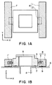
- Figure 1A is a plan view of a moving system according to an embodiment of the present invention
- Figure 1B is a sectional view of the same.
- a reference structure 4 is formed with a plane guide surface 6 which provides a reference.
- a movable member 3 is supported by a static bearing 7, without contact to the plane guide surface 6, and it is movable in a Y direction.
- Mounted on the opposite sides of the movable element 3 are electromagnetic actuators 8 for moving the movable element 3 in the Y direction.
- Each electromagnetic actuator 8 comprises a movable element 2 as well as stators 1 and 1' which are separated and independent from each other with respect to a lateral direction.
- the left-hand and right-hand stators 1 and 1' are supported by a static bearing 9 without contact to the plane guide surface 6, and they are movable in the Y direction.
- the stators 1 and 1' have a predetermined weight, and they have a function as a reaction force counter, to be described later.
- the movable element 2 is connected to a moving unit 3 which can be moved by the movable element 2 in parallel to the plane guide surface.
- the moving unit 3 may be provided with a top plate 5, for example, so that an article to be moved can be placed there.
- the moving unit 3 as a whole, including the movable element 2, constitutes a moving structure which can be moved in the Y direction by means of the electromagnetic actuators 8 having movable elements 2 and stators 1 and 1'.
- the left-hand and right-hand stators 1 and 1' receive a drive reaction force of the force which functions to move the moving unit 3 as a whole, including the movable element2. With this drive reaction force, the stators 1 and 1' displaces along the plane guide surface 6. Through this motion of the stators 1 and 1' along the plane guide surface 6, the stators 1 and 1' can function as a reaction force counter. In this embodiment, if, for example, the moving unit 3 as a whole moves in the positive (+) Y direction, the stators 1 and 1' receive a drive reaction force in the negative (-) Y direction and thus they shift in the negative Y direction.
- each electromagnetic actuator comprises a right-hand linear motor which includes a moving element 2 and a stator 1, and a left-hand linear motor which includes a moving element 2 and a stator 1'.
- the left-hand and right-hand linear motors have a stator provided by a coil, and a moving element provided by a permanent magnet.
- one or more interferometers may be provided to perform the positioning of the moving element 2 and the reference structure 4.
- the position of the stator may be measured by using an interferometer, not shown.
- the reaction force during acceleration or deceleration as the moving unit 3 as a whole of the moving system moves is received by the stators 1 and 1', as a reaction force counter.
- reaction force counter Through the motion of these stators 1 and 1' (reaction force counter), the reaction force is converted into a kinetic energy.
- the action force and the reaction force thereof are confined within the plane of the plane guide surface 6 provided on the reference structure 4, vibration of the machine reference structure 4 by the reaction force can be prevented. Additionally, external disturbance to the floor on which the machine is placed can be avoided, such that production of vibration inside and outside the machine can be prevented.
- any eccentric or biased load as the moving member moves can be made small, and thus the overlay precision is improved.
- the stators 1 and 1' move in a direction opposite to the direction in which the moving member moves, any displacement of the position of the gravity center of the whole structure, including the moving member and the stators, can be suppressed, such that the biased load as the moving member moves can be made small.
- the left-hand and right-hand stators 1 and 1' are provided independently from each other. As a result, even if the left-hand and right-hand electromagnetic actuators produce different outputs, these stators are moved separately to cancel the reaction force.
- the left-hand and right-hand actuators may produce such different outputs, for example, in a case where the moving member should be rotationally moved in a ⁇ direction, or a case where an article placed on the moving member has a biased load with respect to X direction, for example.
- the moving member may be moved in X and Y directions.
- the electromagnetic actuator may preferably comprise a mechanism for producing a driving force in X and Y directions and applying the same to the moving member.
- the stators 1 and 1' may be supported by the static bearing 9 with respect to the plane guide surface 6, and movably in the X and Y directions.
- Figure 2 shows an embodiment in which a stage according to the present invention is provided with position measuring means and driving means, for positioning a movable portion thereof.
- a reference structure 4 has a plane guide surface 6 formed thereon to provide a reference.
- a movable element (not shown) is supported by a static bearing, without contact to the plane guide surface 6, and it is made movable in X and Y directions.
- Mounted on the opposite sides of the movable element 3 are electromagnetic actuators for moving the movable element 3 through a long stroke in the Y direction, and through a short stroke in the X direction.
- Each electromagnetic actuator comprises a movable element 2 as well as stators 1 and 1' which are separated and independent from each other with respect to a lateral direction.
- the left-hand and right-hand stators 1 and 1' are supported by a static bearing 9 without contact to the plane guide surface 6, and they are movable in X and Y directions (along a plane). Also, the stators 1 and 1' have a predetermined weight, and they have a function as a reaction force counter, to be described later.
- the left-hand and right-hand movable elements 2 have two, left-hand and right-hand movable portion Y magnets 10 and two, left-hand and right-hand movable portion X magnets 11, attached to them. Also, there is a top plate 5 mounted on a movable portion, the whole of which is not shown in the drawing.
- the top plate 5 functions as an X-Y stage, and it is moved by the moving elements 2 in a direction parallel to the plane guide surface 6.
- the positional information about the top plate 5 is measured by a laser interferometer which comprises a laser head 16, a Y-axis measurement mirror 17, an X-axis measurement bar mirror 18, two, left-hand and right-hand Y-axis measurement detectors 19, and two, front and rear X-axis measurement detectors 20, for example.
- the Y-axis position of the stators 1 and 1' is measured by means of two, left-hand and right-hand stator Y-axis measurement detectors 21.
- the X-axis position of the top plate 5 is measured by projecting laser light to optical elements 22 and 22' mounted on the top plate 5, in the Y direction. This measurement light is reflected or deflected in the X-axis direction toward the X-axis measurement bar mirror 18, whereby the position is measured by means of the X-axis measurement detectors 20.
- the X-Y stage of this embodiment can be used as a reticle stage or a wafer stage in an exposure apparatus, and an original (reticle) or a substrate (wafer) can be placed on the top plate 5 (X-Y stage) of the moving unit.
- the moving unit having an original (reticle) or a substrate (wafer) placed on its top plate 5 is moved by electromagnetic actuators, having moving elements and stators 1 and 1', in the X and Y directions.
- the stators 1 and 1' receive a drive reaction force of the force acting on the motion of the moving unit as a whole. With this drive reaction force, the stators 1 and 1' move along the plane guide surface. Through the motion of the stators 1 and 1' along the plane guide surface 6, the stators 1 and 1' function as a reaction force counter.
- the stators 1 and 1' receive a drive reaction force in the negative (-) direction, and they move in the negative Y direction.
- the effect of the reaction force counter is substantially the same as that of the preceding embodiment.
- Y-axis position controlling linear motors 14 provided on the reference structure 4, which serve to push back the stators 1 and 1' having moved in the Y-axis direction by an amount greater than a predetermined distance.
- X-axis position controlling linear motors 15 provided on the reference structure 4, which serve to push back the stators 1 and 1' having moved in the X-axis direction by an amount greater than a predetermined distance.
- the stators 1 and 1' can be controlled and placed at the predetermined position. Further, even if there occurs a deviation in the stator position due to the influence of friction or resistance, for example, by using the Y-axis position controlling linear motors and/or the X-axis position controlling linear motors, and without using a drive of the electromagnetic actuators, the stator position can be corrected.
- the exposure apparatus of this embodiment can be applied as a step-and-scan type scanning exposure apparatus in which an exposure is carried out while scanningly moving a reticle and a wafer in synchronism with each other so that a reticle pattern is printed and transferred onto one shot region on the wafer and, by moving the wafer stepwise, patterns are transferred to plural shot regions sequentially.
- the present invention is not limited to a step-and-scan type exposure apparatus. It is effective also to a step-and-repeat type exposure apparatus in which the wafer stage is moved stepwise, at a high speed.
- the reaction force during acceleration or deceleration as the X-Y stage moves is received by the stators, such that, through the motion of these stators in the direction opposite to the X-Y stage, the reaction force is converted into a kinetic energy.
- vibration of the X-Y stage system can be prevented, and the overlay precision, the linewidth precision and the throughput in the exposure process can be improved.
- the two stators move along the machine reference structure in accordance with the acceleration of the X-Y stage, the biased load as the X-Y stage moves can be made small, and the overlay precision can be improved.
- Figure 3 shows an embodiment in which an X-Y stage according to the present invention has a stator position controlling actuator which is mounted on an external structure separate from the reference structure, rather than being mounted on the reference structure as in the second embodiment.
- a reference structure 4 has a plane guide surface 6 formed thereon to provide a reference.
- a movable element (not shown) is supported by a static bearing, without contact to the plane guide surface 6, and it is made movable in X and Y directions.
- Mounted on the opposite sides of the movable element are electromagnetic actuators for moving the movable element through a long stroke in the Y direction, and through a short stroke in the X direction.
- Each electromagnetic actuator comprises a movable element 2 as well as stators 1 and 1' which are separated and independent from each other with respect to a lateral direction.
- the left-hand and right-hand stators 1 and 1' are supported by a static bearing without contact to the plane guide surface 6, and they are movable in X and Y directions (along a plane). Also, the stators 1 and 1' have a predetermined weight, and they have a function as a reaction force counter, to be described later.
- the left-hand and right-hand movable elements 2 have two, left-hand and right-hand movable portion Y magnets 10 and two, left-hand and right-hand movable portion X magnets 11, attached to them. Also, there is a top plate 5 mounted on a movable portion, the whole of which is not shown in the drawing.
- the top plate 5 functions as an X-Y stage, and it is moved by the moving elements 2 in a direction parallel to the plane guide surface 6.
- the positional information about the top plate 5 is measured by a laser interferometer which comprises a laser head, a Y-axis measurement mirror, an X-axis measurement bar mirror, two, left-hand and right-hand Y-axis measurement detectors, and two, front and rear X-axis measurement detectors, for example.
- the Y-axis position of the stators 1 and 1' is measured by means of two, left-hand and right-hand stator Y-axis measurement detectors.
- the X-axis position of the top plate 5 is measured by projecting laser light to optical elements mounted on the top plate 5, in the Y direction. This measurement light is reflected or deflected in the X-axis direction toward the X-axis measurement bar mirror, whereby the position is measured by means of the X-axis measurement detectors.
- two Y-axis position controlling linear motors 14 are provided on an external structure 23, and they function to push back the stators 1 and 1' as they moved in the Y-axis direction by an amount larger than a predetermined.
- the external structure 23 is isolated from the reference structure 4 with respect to vibration.
- the X-Y stage is moved by an amount greater than a predetermined and thus the Y-axis position controlling linear motors 14 and the X-axis position controlling linear motors 15 are driven to bring the stators 1 and 1' to their predetermined positions, the drive reaction force resulting therefrom is not transmitted to the reference structure 4 and thus precise positioning of the movable portion on the reference structure can be accomplished.
- the drive reaction force of the position controlling linear motor is not transmitted to the reference structure 14.
- Figures 4A and 4B show an embodiment in which an exposure apparatus according to the present invention is applied to a fine-motion stage (six-axis motion stage) on which a ⁇ and Z-axis tilt stage is mounted.
- a top plate 5 is provided with a wafer chuck 30 and a position measuring bar mirror 50.
- the wafer chuck 30 serves to vacuum attract a wafer (the subject to be positioned) and hold the same.
- Bar mirrors 50 and 51 reflect measurement light from a laser interferometer, not shown.
- the top plate 5 is floated from an X-Y slider 38, by means of a self-weight compensator (not shown) using a magnet, without contact to the slider, and it has a freedom with respect to six-axis directions.
- the top plate 5 can be minutely driven in six-axis directions (X, Y, and Z directions as well as rotational directions about them), by means of an actuator for producing a driving force between the top plate 5 and the X-Y slider 38.
- the six-axis fine motion actuator comprises two linear motors in X direction, one linear motor in Y direction, and three linear motors in Z direction. Where the two X-direction fine motion linear motors are driven in opposite directions, the top plate can be moved about the Z axis (i.e., in 9 direction).
- the top plate can be moved about the X axis (wX direction) and about the Y axis (wY axis direction), respectively.
- the coil which serves as a stator of the fine-motion linear motor is provided at the X-Y slider 38 side, while the permanent magnet which serves as a movable element of the fine-motion linear motor is provided at the top plate side.
- the X-Y slider 38 top plate is mounted on the X-Y slider 38 being movable along the X-Y plane through a long stroke.
- the X-Y slider 38 is guided by an air bearing (static pressure bearing) 35 along an X guide bar 28 and a Y guide bar 29.
- the X-Y slider 38 is guided with respect to the Z direction, by means of an air bearing (static pressure bearing 35, along the top surface of the reference structure 4.
- movable elements Adjacent to the opposite ends of the X-guide bar 28 and the Y guide bar 29, there are movable elements (magnets) 26 and 27 of the linear motors.
- a Lorentz force is produced, such that the X guide bar 28 can be moved in the Y direction while the Y guide bar 29 can be moved in the X direction.
- the linear motor stators (coils) 24 and 25 are guided along the top surface of the reference structure 4, by means of an air bearing (static pressure bearing), with respect to the Z direction, and they have a freedom with respect to X and Y directions (along a plane).
- the motion of the X-Y slider 38 in the X direction will be explained.
- a force in the X direction is applied to the X-Y slider 38 through the static bearing 35.
- the X-Y slider and the Y guide bar will be called an X movable unit.
- a reaction force thereof is applied to the X linear motor stator 25. Since the X linear motor stator 25 is supported by the static bearing 34, movably in the X and Y directions, due to this reaction force, the X linear motor stator 25 moves in the X direction.
- the acceleration and speed of the motion is determined by the ratio between the mass of the X linear motor stator 25 and the mass of the X movable unit. For example, if the mass of the X linear motor stator 25 is 200 Kg per each while the mass of the X movable unit is 40 Kg, the ratio of mass is 10:1. Therefore, both the acceleration and speed of the X linear motor 21 is one-tenth (1/10) of the X movable unit. In this manner, through the motion of the X linear motor stator 25 in the X direction, in the reference structure no X-direction reaction force is applied to the X linear motor stator 25.
- the X-linear motor stator 25 is provided with at least two linear motors 33 for controlling the position of the linear motor stator, with respect to the X direction, as well as at least one linear motor 33 for controlling the position of the linear motor stator with respect to the Y direction, both for maintaining the relative position with respect to the reference structure 4.
- These linear motors 33 for controlling the position of the linear motor stator function to prevent that, even if the X movable unit is moved beyond a predetermined range, the linear motor stator goes out of a predetermined movement range. Further, even if there occurs a positional deviation due to friction or resistance as the linear motor stator 25 moves, it can be corrected.
- the driving force to be produced by the linear motor is different in accordance with the position of the X-Y slider.
- the X-Y slider 38 moves in the positive (+) Y direction and thereafter it moves in the positive (+) X direction
- the X-Y slider as it moves in the positive X direction is on the side close to the positive Y direction, only the driving force as produced by the upper X linear motor, as viewed in the drawing, is larger than the driving force of the lower X linear motor, as viewed in the drawing.
- a barrel base 39 is supported by a floor or a base structure 40, through a damper 41. Also, the barrel base 39 functions to support a reticle base table 42 and to support a projection optical system 45 disposed between a reticle stage 43 and a wafer stage 44.
- the wafer stage is supported by a stage base table 46 which is supported by the floor or the base structure, and it functions to perform the positioning of a wafer placed thereupon.
- the reticle stage is supported by a reticle stage base table which is supported by the barrel base.
- the reticle stage is movable while carrying thereon a reticle having a circuit pattern formed thereon.
- the exposure light for printing the reticle placed on the reticle stage 43 upon the wafer being placed on the wafer stage 44, is supplied by an illumination optical system 47.
- the wafer stage 44 is scanningly moved in synchronism with the reticle stage 43.
- the positions of them are detected continuously by using respective interferometers, and the detected positions are fed back to the driving unit of the reticle stage 43 and the wafer stage 44.
- the scan start position of these stages can be synchronized with each other, and also the scan speed in a constant-speed scan region can be controlled very precisely.
- the reticle pattern is printed on the wafer by which a circuit pattern is transferred to it.
- the exposure light may be ultraviolet light such as fluorine excimer laser, ArF excimer laser and KrF excimer laser, for example.
- the movable element and the stator may have an telescopic structure such as shown in Figure 6A or an open structure such as shown in Figure 6B.
- the electromagnetic actuators each having a movable element 2 and left-hand and right-hand stators 1 and 1', being separated and independent from each other.
- the left-hand and right-hand stators 1 and 1' function also as a reaction force counter having a predetermined weight. They are movable along the plane guide surface 6 on the reference structure 4.
- the stators 1 and 1' are supported at the opposite ends of the straight direction.
- the movable element 2 is connected to a moving unit 3 being movable in parallel to the plane guide surface by the moving element 2.
- a top plate 5, for example, may be provided on the movable unit 3, so that an article to be moved can be placed there.
- an open structure such as shown in Figure 6B is used, the structure and function will be the same as has been described with reference to the first embodiment.
- X-Y stages and exposure apparatuses may use any one of the telescopic structure and the open structure.
- oxygens and water content along the path of ultraviolet light must be purged completely.
- FIGS 7A and 7B shows an exposure apparatus according to an embodiment of the present invention, in which the relationship between a stator and a movable element of a linear motor in an X-Y stage is based on an open structure, not a telescopic structure.
- a shielding wall provided inside the stator, and it extends from an illumination optical system to an end face of a substrate structure which serves also as a projection optical system, including a movable unit on which a reticle is placed.
- the inside space of this wall is purged by using an inactive gas.
- Figure 7A is a perspective view about an X-Y stage on which a reticle is placed
- Figure 7B is a section as viewed from a direction A in Figure 7A.
- each electromagnetic actuator comprises a movable element 2 (permanent magnet) and left-hand and right-hand stators 1 and 1'.
- the stators 1 and 1' are separated and independent from each other, and each has coils 48a and a yoke 48b.
- the stators 1 and 1' function also as a reaction force counter having a predetermined weight. They can be moved freely along the plane guide surface 6 of the reference structure 4.
- Mounted on a movable unit 3 having left-hand and right-hand movable elements 3 is a top plate 5. This top plate 5 functions as an X-Y stage.
- a reticle 52 is placed on the top plate 5, and it can be moved by the movable elements 2, in parallel to the plane guide surface 6.
- Mounted on the top plate 5 are a mirror of an interferometer, or bar mirrors 52a, 52b and 52c. These components cooperate with detectors 49a, 49b and 49c as well as a laser head (not shown), or the like, to provide an interferometer.
- a shielding wall 53 for covering the movable elements 2, the movable unit 3, the top plate 5, the reticle 52 as well as the mirrors, bar mirrors and detectors which constitute an interferometer.
- the shielding wall 53 extends from the illumination optical system 54 to an end face of a substrate structure, which functions also as the projection optical system 55.
- the stators 1 and l' have an open structure, not a telescopic structure.
- the inside space of the shielding wall is purged by an inactive gas, against impurities.
- the relation between the stator and the movable element of the linear motor for the stage is based on an open type structure, and a shielding wall is provided between the stator and the movable element.
- the inside space is purged against impurities, by using an inactive gas.
- the purge space around a reticle can be made compact, and the replacing time of inactive gas can be made short.
- the stator is outside the purge space, it is not influenced by degassing from the stator.
- the reticle stage may be made movable in the X-axis direction about a movable element, thereby to provide an X-Y stage.
- a ⁇ Z tilt stage may be mounted to provide a six-axis movable wafer stage.
- a manufacturing system for semiconductor devices such as semiconductor chips (e.g., IC or LSI), liquid crystal panels, CCDs, thin film magnetic heads, or micro-machines, for example, will be described.
- This system is arranged so that repair of any disorder occurring in a production machine placed in a semiconductor manufacturing factory or periodic maintenance thereof or, alternatively, a maintenance service such as software supply, can be made by use of a computer network outside the manufacturing factory.
- Figure 8 is a schematic view of a general structure of the production system, in a certain aspect thereof.
- Denoted in the drawing at 101 is a business office of a vendor (machine supplying maker) for providing semiconductor device manufacturing apparatuses.
- pre-process machines various lithographic apparatuses such as an exposure apparatus, a resist coating apparatus, an etching apparatus, for example, as well as a heat treatment apparatus, a film forming apparatus, and a flattening apparatus
- post-process machines an assembling machine and an inspection machine, for example
- a host control system 108 for providing maintenance database for the production machines, plural operating terminal computers 110, and a local area network (LAN) 109 for connecting them to constitute an intranet.
- the host control system 108 is provided with a gateway for connecting the LAN 109 to an internet 105 which is an outside network of the office, and a security function for restricting the access from the outside.
- each factories 102 - 104 there are production machines 106, a local area network (LAN) 111 for connecting them to constitute an intranet, and a host control system 107 as a monitoring system for monitoring the state of operation of the production machines 106.
- the host control system 107 in each factory 102 - 104 is provided with a gateway for connecting the LAN 111 in the factory to the internet 105 which is an outside network of the factory.
- the host control system 108 of the vendor 101 can be accessed from the LAN 111 in each factory, through the internet 105. Further, due to the security function of the host control system 108, only admitted users can access thereto. More specifically, through the internet 105, status information representing the state of operation of the production machines 106 (for example, the state of the machine in which any disorder has occurred) may be transmitted as a notice from the factory to the vendor. Additionally, any response information which is responsive to the notice (that is, for example, information on how the disorder should be treated or software data concerning the treatment) as well as a latest software program and maintenance information such as help information, may be supplied from the vendor.
- the data communication between each factory 102 - 104 and the vendor 101 as well as the data communication through the LAN 111 in each factory, may use a communication protocol (TCP/IP) generally used in the internet.
- TCP/IP communication protocol
- an exclusive line network e.g., ISDN
- the host control system is not limited to the system as provided by the vendor.
- a database may be structured by the user and it may be set in an outside network, such that it can be accessed from plural user factories.
- Figure 9 is a schematic view of a general structure of the production system according to this embodiment, in another aspect thereof different from that of Figure 8.
- plural user factories each having production machines and the control system of the vendor of the production machines are connected with each other through an external network, so that, through this external network, information related to the production control in each factory or information related to at least one production machine can be data communicated.
- a factory having production machines supplied from different vendors and control systems of these vendors corresponding to the user production machines are connected with each other through an external network, outside the factory, so that the maintenance information for these production machines can be data communicated.
- 201 Denoted in the drawing at 201 is a manufacturing factory of a production machine user (i.e., a semiconductor device manufacturer). Along the production line in the factory, there are many production machines for performing various processes, that is, in this example, an exposure apparatus 201, a resist processing apparatus 203, and a film formation processing apparatus 204 introduced. Although only one factory 201 is illustrated in the drawing, in practice, plural factories may be arranged into the network. Each production machine in the factory is connected through a LAN 206 to constitute an intranet. The operation of the production line is controlled by a host control system 205.
- a host control system 205 The operation of the production line is controlled by a host control system 205.
- the business offices of vendors such as an exposure apparatus manufacturer 210, a resist processing machine manufacturer 220, and a film forming machine manufacturer 230
- host control systems 211, 221 and 213 for performing remote control maintenance for the machines they supplied.
- Each of these host control systems is equipped with a maintenance database and a gateway for the outside network.
- the host control system 205 for controlling the machines in the user factory and the control systems 211, 221 and 231 of the machine vendors are connected with each other through the external network 200 (internet) or an exclusive line network. If, in this production system, any disorder occurs in any one of the production machines in the production line, the operation of the production machine is stopped. However, this can be met quickly through the remote control maintenance for the disordered machine, from the corresponding machine vendor and by way of the internet 200. Therefore, the suspension of the production line is short.
- Each of the production machines in the factory may have a display, a network interface and a computer for executing network accessing softwares, stored in a storage device, as well as machine operating softwares.
- the storage device may be an internal memory or a hard disk or, alternatively, it may be a network file server.
- the network accessing softwares may include an exclusive or wide-use web browser, and an user screen interface such as shown in Figure 10, for example, may be provided on the display.
- Various data may be inputted into the computer (input zones on the screen) by an operator who controls the production machines in each factory, such as, for example, machine type (401), serial number (402), trouble file name (403), date of disorder (404), emergency level (405), status (406), solution or treatment (407), and progress (408).
- the thus inputted information is transmitted to the maintenance database through the internet.
- appropriate maintenance information is replied from the maintenance database to the user's display.
- the user interface as provided by the web browser enables a hyperlink function (410 - 412) as illustrated.
- the operator can access further details of information in each items, or he/she can get a latest version software to be used for the production machine, from the software library as provided by the vendor. Alternatively, the operator can get an operation guide (help information) prepared for factory operators.
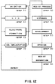
- Figure 12 is a flow chart of a general procedure for manufacture of microdevices.
- Step 1 is a design process for designing a circuit of a semiconductor device.
- Step 2 is a process for making a mask on the basis of the circuit pattern design.
- Step 3 is a process for preparing a wafer by using a material such as silicon.
- Step 4 is a wafer process (called a pre-process) wherein, by using the so prepared mask and wafer, circuits are practically formed on the wafer through lithography.
- Step 5 subsequent to this is an assembling step (called a post-process) wherein the wafer having been processed by step 4 is formed into semiconductor chips.
- This step includes an assembling (dicing and bonding) process and a packaging (chip sealing) process.
- Step 6 is an inspection step wherein operation check, durability check and so on for the semiconductor devices provided by step 5, are carried out. With these processes, semiconductor devices are completed and they are shipped (step 7).
- the pre-process and the post-process may be performed in separate exclusive factories. In each factory, the maintenance is carried out on the basis of the remote maintenance system described hereinbefore. Further, between the pre-process factory and the post-process factory, data communication for the information related to the production control and the machine maintenance may be done by use of the internet or an exclusive line network.
- Figure 13 is a flow chart showing details of the wafer process.
- Step 11 is an oxidation process for oxidizing the surface of a wafer.
- Step 12 is a CVD process for forming an insulating film on the wafer surface.
- Step 13 is an electrode forming process for forming electrodes upon the wafer by vapor deposition.
- Step 14 is an ion implanting process for implanting ions to the wafer.
- Step 15 is a resist process for applying a resist (photosensitive material) to the wafer.
- Step 16 is an exposure process for printing, by exposure, the circuit pattern of the mask on the wafer through the exposure apparatus described above.
- Step 17 is a developing process for developing the exposed wafer.
- Step 18 is an etching process for removing portions other than the developed resist image.
- Step 19 is a resist separation process for separating the resist material remaining on the wafer after being subjected to the etching process. By repeating these processes, circuit patterns are superposedly formed on the wafer.
- any disorder may be prevented beforehand. If it occurs, it can be met quickly. Therefore, the device productivity can be improved significantly.
- a reaction force during acceleration or deceleration as a movable portion moves is received by a stator.
- the stator having reaction force received moves, by which the reaction force is converted into a kinetic energy of the stator, whereby the stator functions as a reaction force counter.
- the influence of vibration or swinging motion resulting from the motion of the stage can be reduced, such that the overlay precision, the linewidth precision, the throughput can be improved. Further, since the biased load as the moving element moves can be made smaller, the overlay precision can be improved. Further, because the influence of the reaction force, due to the acceleration or deceleration of the stage, can be reduced, the influence to the other machines placed on the same floor, can be made smaller. Also, enlargement the area to be occupied by the apparatus can be prevented.
- the purge space around a reticle stage can be made compact and, therefore, the replacement time is shortened. Also, since the stator is outside the purge space, the effect of degassing of the stator is avoided.
- the transmission factor at the path of ultraviolet light, more particularly, fluorine laser, as well as the stability of the same are assured. As a result, high precision and high throughput exposures are accomplished.
Landscapes
- Physics & Mathematics (AREA)
- Health & Medical Sciences (AREA)
- Engineering & Computer Science (AREA)
- General Physics & Mathematics (AREA)
- Epidemiology (AREA)
- Public Health (AREA)
- Atmospheric Sciences (AREA)
- Environmental & Geological Engineering (AREA)
- Life Sciences & Earth Sciences (AREA)
- Chemical & Material Sciences (AREA)
- Toxicology (AREA)
- Combustion & Propulsion (AREA)
- Electromagnetism (AREA)
- Power Engineering (AREA)
- Exposure And Positioning Against Photoresist Photosensitive Materials (AREA)
- Container, Conveyance, Adherence, Positioning, Of Wafer (AREA)
- Exposure Of Semiconductors, Excluding Electron Or Ion Beam Exposure (AREA)
- Details Of Measuring And Other Instruments (AREA)
- Linear Motors (AREA)
Applications Claiming Priority (2)
| Application Number | Priority Date | Filing Date | Title |
|---|---|---|---|
| JP2000190140 | 2000-06-23 | ||
| JP2000190140A JP4474020B2 (ja) | 2000-06-23 | 2000-06-23 | 移動装置及び露光装置 |
Publications (3)
| Publication Number | Publication Date |
|---|---|
| EP1168084A2 true EP1168084A2 (de) | 2002-01-02 |
| EP1168084A3 EP1168084A3 (de) | 2005-05-25 |
| EP1168084B1 EP1168084B1 (de) | 2008-10-29 |
Family
ID=18689655
Family Applications (1)
| Application Number | Title | Priority Date | Filing Date |
|---|---|---|---|
| EP01305451A Expired - Lifetime EP1168084B1 (de) | 2000-06-23 | 2001-06-22 | Antriebsmechanismus und damit versehener Belichtungsapparat |
Country Status (6)
| Country | Link |
|---|---|
| US (1) | US6717653B2 (de) |
| EP (1) | EP1168084B1 (de) |
| JP (1) | JP4474020B2 (de) |
| KR (1) | KR100428003B1 (de) |
| DE (1) | DE60136311D1 (de) |
| TW (1) | TWI230411B (de) |
Cited By (4)
| Publication number | Priority date | Publication date | Assignee | Title |
|---|---|---|---|---|
| EP1367636A3 (de) * | 2002-05-27 | 2005-03-09 | Canon Kabushiki Kaisha | Unterstützungsvorrichtung mit mehreren Magneten und Vefahren dafür |
| US6891597B2 (en) * | 2002-04-22 | 2005-05-10 | Canon Kabushiki Kaisha | Driving apparatus, exposure apparatus, and device manufacturing method |
| US7283200B2 (en) | 2003-07-17 | 2007-10-16 | Nikon Corporation | System and method for measuring displacement of a stage |
| WO2008032080A3 (en) * | 2006-09-13 | 2009-03-19 | Wireless Motor Developments Lt | Improvements in electromagnetic machines |
Families Citing this family (42)
| Publication number | Priority date | Publication date | Assignee | Title |
|---|---|---|---|---|
| US6246204B1 (en) * | 1994-06-27 | 2001-06-12 | Nikon Corporation | Electromagnetic alignment and scanning apparatus |
| JP2003059797A (ja) * | 2001-08-09 | 2003-02-28 | Canon Inc | 移動装置、ステージ装置及び露光装置 |
| JP4011919B2 (ja) * | 2002-01-16 | 2007-11-21 | キヤノン株式会社 | 移動装置及び露光装置並びに半導体デバイスの製造方法 |
| US6809323B2 (en) * | 2002-04-03 | 2004-10-26 | Nikon Corporation | Isolated frame caster |
| US7268504B2 (en) * | 2002-05-24 | 2007-09-11 | Kollomorgen Corporation | Stator position feedback controller |
| JP3962669B2 (ja) | 2002-10-08 | 2007-08-22 | キヤノン株式会社 | 移動装置及び露光装置並びにデバイスの製造方法 |
| US6983703B2 (en) * | 2002-11-05 | 2006-01-10 | Asm Technology Singapore Pte Ltd | Driving means to position a load |
| US20040160132A1 (en) * | 2003-02-14 | 2004-08-19 | Carter Frederick Michael | System and method to reduce the effect of reactive forces on a stage using a balance mass |
| JP2004253741A (ja) | 2003-02-21 | 2004-09-09 | Sumitomo Eaton Noba Kk | 移動装置及び半導体製造装置 |
| EP1475668A1 (de) * | 2003-05-09 | 2004-11-10 | ASML Netherlands B.V. | Verfahren zur Herstellung von Komponenten für einen lithographischen Apparat |
| WO2004105105A1 (ja) * | 2003-05-21 | 2004-12-02 | Nikon Corporation | ステージ装置及び露光装置、並びにデバイス製造方法 |
| JP2004356222A (ja) | 2003-05-27 | 2004-12-16 | Canon Inc | ステージ装置及びその制御方法、露光装置、並びにデバイス製造方法 |
| JP2005005393A (ja) * | 2003-06-10 | 2005-01-06 | Canon Inc | ステージ装置、露光装置、およびデバイス製造方法 |
| JP4590846B2 (ja) * | 2003-09-01 | 2010-12-01 | 株式会社ニコン | 磁気浮上式ステージ装置及び露光装置 |
| JP2005203567A (ja) * | 2004-01-15 | 2005-07-28 | Canon Inc | 駆動装置、露光装置及びデバイス製造方法 |
| JP2005216132A (ja) | 2004-01-30 | 2005-08-11 | Sumitomo Eaton Noba Kk | 移動装置の制御方法、及び移動装置の連動装置、及び移動装置の連動方法、及び半導体製造装置、及び液晶製造装置、及びメカニカルスキャンイオン注入装置 |
| US7456527B2 (en) * | 2004-03-04 | 2008-11-25 | Asml Netherlands B.V. | Moveable object carrier, lithographic apparatus comprising the moveable object carrier and device manufacturing method |
| US7376961B2 (en) * | 2004-05-28 | 2008-05-20 | International Business Machines Corporation | Contactless power and/or data transmission in an automated data storage library employing segmented coils |
| US7654540B2 (en) * | 2004-06-18 | 2010-02-02 | Bose Corporation | Electromechanical transducing |
| JP4617119B2 (ja) * | 2004-08-30 | 2011-01-19 | キヤノン株式会社 | 駆動装置、露光装置及びデバイス製造方法 |
| US20060054432A1 (en) * | 2004-09-16 | 2006-03-16 | Yu-Yen Chiu | Anti-shock system |
| US7385678B2 (en) * | 2004-10-05 | 2008-06-10 | Asml Netherlands B.V. | Positioning device and lithographic apparatus |
| JP2006120798A (ja) * | 2004-10-20 | 2006-05-11 | Canon Inc | 露光装置 |
| JP4614386B2 (ja) | 2005-02-04 | 2011-01-19 | キヤノン株式会社 | 位置決め装置、露光装置およびそれを用いたデバイス製造方法 |
| US7456935B2 (en) * | 2005-04-05 | 2008-11-25 | Asml Netherlands B.V. | Lithographic apparatus and device manufacturing method utilizing a positioning device for positioning an object table |
| US7273289B2 (en) | 2005-05-19 | 2007-09-25 | Euv Llc | Vacuum compatible, high-speed, 2-D mirror tilt stage |
| JP2007312516A (ja) * | 2006-05-18 | 2007-11-29 | Canon Inc | 駆動装置、露光装置及びデバイス製造方法 |
| DE502007002871D1 (de) * | 2007-08-07 | 2010-04-01 | Micronas Gmbh | Positioniereinrichtung zum Positionieren einer Blende in einem lonenstrahl |
| JP2009136065A (ja) * | 2007-11-29 | 2009-06-18 | Canon Inc | 平面モータおよびそれを用いたステージ |
| KR102211255B1 (ko) * | 2009-05-15 | 2021-02-02 | 가부시키가이샤 니콘 | 이동체 장치, 용력 전달 장치, 및 노광 장치, 그리고 디바이스 제조 방법 |
| JP5618261B2 (ja) * | 2009-08-07 | 2014-11-05 | 株式会社ニコン | 露光装置及びデバイス製造方法 |
| NL2005240A (en) * | 2009-09-22 | 2011-03-23 | Asml Netherlands Bv | Actuator, positioning system and lithographic apparatus. |
| JP5677025B2 (ja) * | 2010-10-22 | 2015-02-25 | 株式会社トプコン | 載置ステージ |
| JP5836057B2 (ja) * | 2011-10-26 | 2015-12-24 | カヤバ システム マシナリー株式会社 | 振動装置 |
| JP5539293B2 (ja) * | 2011-11-24 | 2014-07-02 | キヤノン株式会社 | 露光装置、およびデバイス製造方法 |
| CN104617734B (zh) * | 2015-02-02 | 2017-05-10 | 瑞声光电科技(常州)有限公司 | 扁平线性振动电机 |
| CN104617735B (zh) * | 2015-02-02 | 2017-09-08 | 瑞声光电科技(常州)有限公司 | 扁平线性振动电机 |
| CN104660106B (zh) * | 2015-02-02 | 2017-04-12 | 瑞声精密电子沭阳有限公司 | 扁平线性振动电机 |
| CN104617736B (zh) * | 2015-02-02 | 2017-08-04 | 瑞声光电科技(常州)有限公司 | 扁平线性振动电机 |
| JP6938457B2 (ja) * | 2018-08-08 | 2021-09-22 | キヤノン株式会社 | 搬送システム、可動子、制御装置及び制御方法 |
| JP7759200B2 (ja) * | 2021-07-07 | 2025-10-23 | キヤノン株式会社 | 駆動装置の制御方法、駆動装置、リソグラフィ装置、および物品の製造方法 |
| CN114362471B (zh) * | 2021-12-10 | 2023-07-14 | 浙江大学杭州国际科创中心 | 双级多自由度空间位置精密稳定系统 |
Family Cites Families (23)
| Publication number | Priority date | Publication date | Assignee | Title |
|---|---|---|---|---|
| JP2780837B2 (ja) * | 1990-01-24 | 1998-07-30 | 住友重機械工業株式会社 | 可動ステージ装置 |
| NL9100407A (nl) | 1991-03-07 | 1992-10-01 | Philips Nv | Optisch lithografische inrichting met een krachtgecompenseerd machinegestel. |
| JP2714502B2 (ja) | 1991-09-18 | 1998-02-16 | キヤノン株式会社 | 移動ステージ装置 |
| US5684856A (en) | 1991-09-18 | 1997-11-04 | Canon Kabushiki Kaisha | Stage device and pattern transfer system using the same |
| DE4303643A1 (de) | 1993-02-09 | 1994-08-11 | Philips Patentverwaltung | Röntgenanlage |
| US5559584A (en) | 1993-03-08 | 1996-09-24 | Nikon Corporation | Exposure apparatus |
| US5874820A (en) * | 1995-04-04 | 1999-02-23 | Nikon Corporation | Window frame-guided stage mechanism |
| JPH08229759A (ja) * | 1995-02-24 | 1996-09-10 | Canon Inc | 位置決め装置並びにデバイス製造装置及び方法 |
| JP3473649B2 (ja) | 1995-04-07 | 2003-12-08 | 株式会社ニコン | 投影露光装置 |
| US5586059A (en) * | 1995-06-07 | 1996-12-17 | Advanced Micro Devices, Inc. | Automated data management system for analysis and control of photolithography stepper performance |
| JP3636337B2 (ja) | 1996-06-07 | 2005-04-06 | 株式会社ニコン | 除振装置及び露光装置 |
| JPH09289155A (ja) | 1996-04-19 | 1997-11-04 | Nikon Corp | 走査型露光装置 |
| KR19980031092A (ko) * | 1996-10-31 | 1998-07-25 | 김영환 | 웨이퍼 노광 방법 |
| US5815246A (en) * | 1996-12-24 | 1998-09-29 | U.S. Philips Corporation | Two-dimensionally balanced positioning device, and lithographic device provided with such a positioning device |
| KR100512450B1 (ko) * | 1996-12-24 | 2006-01-27 | 에이에스엠엘 네델란즈 비.브이. | 두개의물체홀더를가진이차원적으로안정화된위치설정장치와이런위치설정장치를구비한리소그래픽장치 |
| JPH11297589A (ja) * | 1998-04-09 | 1999-10-29 | Dainippon Screen Mfg Co Ltd | 基板処理装置 |
| US6252234B1 (en) * | 1998-08-14 | 2001-06-26 | Nikon Corporation | Reaction force isolation system for a planar motor |
| JP2000077503A (ja) * | 1998-08-28 | 2000-03-14 | Nikon Corp | ステージ装置及び露光装置 |
| EP1111470B1 (de) * | 1999-12-21 | 2007-03-07 | ASML Netherlands B.V. | Lithographischer Apparat mit einem ausbalancierten Positionierungssystem |
| TW546551B (en) * | 1999-12-21 | 2003-08-11 | Asml Netherlands Bv | Balanced positioning system for use in lithographic apparatus |
| US6271606B1 (en) * | 1999-12-23 | 2001-08-07 | Nikon Corporation | Driving motors attached to a stage that are magnetically coupled through a chamber |
| DE60136667D1 (de) * | 2000-02-21 | 2009-01-08 | Sharp Kk | Präzisionsträgerplatte |
| JP2001274054A (ja) * | 2000-03-24 | 2001-10-05 | Canon Inc | 露光装置、半導体デバイス製造方法および半導体デバイス製造工場 |
-
2000
- 2000-06-23 JP JP2000190140A patent/JP4474020B2/ja not_active Expired - Fee Related
-
2001
- 2001-06-21 US US09/885,012 patent/US6717653B2/en not_active Expired - Fee Related
- 2001-06-22 EP EP01305451A patent/EP1168084B1/de not_active Expired - Lifetime
- 2001-06-22 TW TW090115192A patent/TWI230411B/zh not_active IP Right Cessation
- 2001-06-22 DE DE60136311T patent/DE60136311D1/de not_active Expired - Lifetime
- 2001-06-23 KR KR10-2001-0035992A patent/KR100428003B1/ko not_active Expired - Fee Related
Cited By (7)
| Publication number | Priority date | Publication date | Assignee | Title |
|---|---|---|---|---|
| US6891597B2 (en) * | 2002-04-22 | 2005-05-10 | Canon Kabushiki Kaisha | Driving apparatus, exposure apparatus, and device manufacturing method |
| EP1357432B1 (de) * | 2002-04-22 | 2013-01-09 | Canon Kabushiki Kaisha | Antriebvorrichtung |
| EP1367636A3 (de) * | 2002-05-27 | 2005-03-09 | Canon Kabushiki Kaisha | Unterstützungsvorrichtung mit mehreren Magneten und Vefahren dafür |
| US6954041B2 (en) | 2002-05-27 | 2005-10-11 | Canon Kabushiki Kaisha | Supporting apparatus having a plurality of magnets that generate a floating force and method, stage apparatus, and exposure apparatus |
| US7283200B2 (en) | 2003-07-17 | 2007-10-16 | Nikon Corporation | System and method for measuring displacement of a stage |
| WO2008032080A3 (en) * | 2006-09-13 | 2009-03-19 | Wireless Motor Developments Lt | Improvements in electromagnetic machines |
| US8232689B2 (en) | 2006-09-13 | 2012-07-31 | Guilden Limited | Electromagnetic machines |
Also Published As
| Publication number | Publication date |
|---|---|
| KR20020000528A (ko) | 2002-01-05 |
| JP2002008971A (ja) | 2002-01-11 |
| JP4474020B2 (ja) | 2010-06-02 |
| KR100428003B1 (ko) | 2004-05-04 |
| EP1168084A3 (de) | 2005-05-25 |
| US20020018195A1 (en) | 2002-02-14 |
| TWI230411B (en) | 2005-04-01 |
| EP1168084B1 (de) | 2008-10-29 |
| DE60136311D1 (de) | 2008-12-11 |
| US6717653B2 (en) | 2004-04-06 |
Similar Documents
| Publication | Publication Date | Title |
|---|---|---|
| EP1168084B1 (de) | Antriebsmechanismus und damit versehener Belichtungsapparat | |
| US6512571B2 (en) | Anti-vibration system for exposure apparatus | |
| US7063192B2 (en) | Active vibration suppression apparatus, control method therefor, and exposure apparatus having active vibration suppression apparatus | |
| JP3554186B2 (ja) | 露光装置、デバイス製造方法および反力受け方法 | |
| US20040095563A1 (en) | Moving stage device in exposure apparatus | |
| US6654098B2 (en) | Stage apparatus, exposure apparatus, and device production method | |
| WO2001027978A1 (en) | Substrate, stage device, method of driving stage, exposure system and exposure method | |
| US7336344B2 (en) | Positioning system, exposure apparatus using the same, and device manufacturing method | |
| WO2008143337A1 (en) | Monolithic, non-contact six degree-of-freedom stage apparatus | |
| US7586218B2 (en) | Moving apparatus, exposure apparatus, and device manufacturing method | |
| US7292317B2 (en) | Lithographic apparatus and device manufacturing method utilizing substrate stage compensating | |
| JP2000021702A (ja) | 露光装置ならびにデバイス製造方法 | |
| KR100516689B1 (ko) | 구동장치, 노광장치 및 디바이스제조방법 | |
| US6320645B1 (en) | Stage system and exposure apparatus, and device manufacturing method using the same | |
| JP3720680B2 (ja) | ステージ装置、露光装置およびデバイス製造方法 | |
| US6658083B2 (en) | Weight compensation apparatus, stage apparatus using the same, and exposure apparatus | |
| JP2004193425A (ja) | 移動制御方法及び装置、露光装置、並びにデバイス製造方法 | |
| JP2000040650A (ja) | 走査型露光装置およびデバイス製造方法 | |
| US7346414B2 (en) | Moving mechanism and stage system in exposure apparatus | |
| US7253877B2 (en) | Exposure apparatus, and device manufacturing method | |
| JP2005322720A (ja) | ステージ制御装置及び方法、露光装置及び方法、並びにデバイス製造方法 | |
| JP3963426B2 (ja) | ステージ装置および露光装置 | |
| JP4011919B2 (ja) | 移動装置及び露光装置並びに半導体デバイスの製造方法 | |
| JPH11297616A (ja) | ステージ装置およびこれを用いた露光装置ならびにデバイス製造方法 | |
| JP2001297965A (ja) | ステージ装置及びこれを用いた露光装置並びにデバイス製造方法 |
Legal Events
| Date | Code | Title | Description |
|---|---|---|---|
| PUAI | Public reference made under article 153(3) epc to a published international application that has entered the european phase |
Free format text: ORIGINAL CODE: 0009012 |
|
| AK | Designated contracting states |
Kind code of ref document: A2 Designated state(s): AT BE CH CY DE DK ES FI FR GB GR IE IT LI LU MC NL PT SE TR |
|
| AX | Request for extension of the european patent |
Free format text: AL;LT;LV;MK;RO;SI |
|
| PUAL | Search report despatched |
Free format text: ORIGINAL CODE: 0009013 |
|
| AK | Designated contracting states |
Kind code of ref document: A3 Designated state(s): AT BE CH CY DE DK ES FI FR GB GR IE IT LI LU MC NL PT SE TR |
|
| AX | Request for extension of the european patent |
Extension state: AL LT LV MK RO SI |
|
| 17P | Request for examination filed |
Effective date: 20051125 |
|
| AKX | Designation fees paid |
Designated state(s): DE GB NL |
|
| R17C | First examination report despatched (corrected) |
Effective date: 20060418 |
|
| GRAP | Despatch of communication of intention to grant a patent |
Free format text: ORIGINAL CODE: EPIDOSNIGR1 |
|
| GRAS | Grant fee paid |
Free format text: ORIGINAL CODE: EPIDOSNIGR3 |
|
| GRAA | (expected) grant |
Free format text: ORIGINAL CODE: 0009210 |
|
| AK | Designated contracting states |
Kind code of ref document: B1 Designated state(s): DE GB NL |
|
| REG | Reference to a national code |
Ref country code: GB Ref legal event code: FG4D |
|
| REF | Corresponds to: |
Ref document number: 60136311 Country of ref document: DE Date of ref document: 20081211 Kind code of ref document: P |
|
| PLBE | No opposition filed within time limit |
Free format text: ORIGINAL CODE: 0009261 |
|
| STAA | Information on the status of an ep patent application or granted ep patent |
Free format text: STATUS: NO OPPOSITION FILED WITHIN TIME LIMIT |
|
| 26N | No opposition filed |
Effective date: 20090730 |
|
| PGFP | Annual fee paid to national office [announced via postgrant information from national office to epo] |
Ref country code: NL Payment date: 20100616 Year of fee payment: 10 |
|
| PGFP | Annual fee paid to national office [announced via postgrant information from national office to epo] |
Ref country code: GB Payment date: 20100401 Year of fee payment: 10 |
|
| REG | Reference to a national code |
Ref country code: NL Ref legal event code: V1 Effective date: 20120101 |
|
| GBPC | Gb: european patent ceased through non-payment of renewal fee |
Effective date: 20110622 |
|
| PG25 | Lapsed in a contracting state [announced via postgrant information from national office to epo] |
Ref country code: NL Free format text: LAPSE BECAUSE OF NON-PAYMENT OF DUE FEES Effective date: 20120101 |
|
| PG25 | Lapsed in a contracting state [announced via postgrant information from national office to epo] |
Ref country code: GB Free format text: LAPSE BECAUSE OF NON-PAYMENT OF DUE FEES Effective date: 20110622 |
|
| PGFP | Annual fee paid to national office [announced via postgrant information from national office to epo] |
Ref country code: DE Payment date: 20140630 Year of fee payment: 14 |
|
| REG | Reference to a national code |
Ref country code: DE Ref legal event code: R119 Ref document number: 60136311 Country of ref document: DE |
|
| PG25 | Lapsed in a contracting state [announced via postgrant information from national office to epo] |
Ref country code: DE Free format text: LAPSE BECAUSE OF NON-PAYMENT OF DUE FEES Effective date: 20160101 |