EP1167632A2 - Vibrator mit einer Linearantriebseinheit - Google Patents
Vibrator mit einer Linearantriebseinheit Download PDFInfo
- Publication number
- EP1167632A2 EP1167632A2 EP01114622A EP01114622A EP1167632A2 EP 1167632 A2 EP1167632 A2 EP 1167632A2 EP 01114622 A EP01114622 A EP 01114622A EP 01114622 A EP01114622 A EP 01114622A EP 1167632 A2 EP1167632 A2 EP 1167632A2
- Authority
- EP
- European Patent Office
- Prior art keywords
- linear drive
- drive unit
- piston rod
- cylinder
- rotary
- Prior art date
- Legal status (The legal status is an assumption and is not a legal conclusion. Google has not performed a legal analysis and makes no representation as to the accuracy of the status listed.)
- Granted
Links
- 230000001360 synchronised effect Effects 0.000 claims abstract description 15
- 230000010355 oscillation Effects 0.000 claims abstract description 4
- 230000003534 oscillatory effect Effects 0.000 claims description 4
- 238000013016 damping Methods 0.000 claims description 3
- 238000006243 chemical reaction Methods 0.000 description 2
- 230000001960 triggered effect Effects 0.000 description 2
- 238000010276 construction Methods 0.000 description 1
- 230000008878 coupling Effects 0.000 description 1
- 238000010168 coupling process Methods 0.000 description 1
- 238000005859 coupling reaction Methods 0.000 description 1
- 238000010586 diagram Methods 0.000 description 1
- 238000005516 engineering process Methods 0.000 description 1
- 230000001788 irregular Effects 0.000 description 1
Images
Classifications
-
- E—FIXED CONSTRUCTIONS
- E02—HYDRAULIC ENGINEERING; FOUNDATIONS; SOIL SHIFTING
- E02D—FOUNDATIONS; EXCAVATIONS; EMBANKMENTS; UNDERGROUND OR UNDERWATER STRUCTURES
- E02D7/00—Methods or apparatus for placing sheet pile bulkheads, piles, mouldpipes, or other moulds
- E02D7/02—Placing by driving
- E02D7/06—Power-driven drivers
- E02D7/10—Power-driven drivers with pressure-actuated hammer, i.e. the pressure fluid acting directly on the hammer structure
Definitions
- the invention relates to a vibrator for acting on rammed material, such as Sheet piles, piles, channel boards, with a linear drive unit in shape at least one hydraulic cylinder, the at least one piston rod under Action of a controller with respect to the linear drive unit receiving supporting frame is moved alternately in a straight line back and forth and thereby their vibrational movements on one with the pile connected holding element transmits, which by means of Linear drive unit generated vibration frequency and that of it outgoing driving force are changeable.
- rammed material such as Sheet piles, piles, channel boards
- a vibrator of the type mentioned which as a linear drive unit has a hydraulically operated differential cylinder arranged in a support frame; whose Koblenbstange acts directly on the pile via a holding element attached to it in the form of a clamping head.
- the support frame On the side opposite the holding element, the support frame is equipped with a fastening means, via which it can be attached to a carrier device.
- a control rotor is assigned to the differential cylinder, via the rotary slide of which the larger or smaller (rod-side) piston surface is alternately connected to a pressure line pressurized with working pressure, while the other piston surface is kept depressurized via a tank line at the same time.
- the oscillation frequency of the differential cylinder can be changed as desired.
- the driving force generated by the differential cylinder can be influenced by changing the working pressure generated by a hydraulic pump.
- the prior publication in question discloses embodiments of a vibrator equipped with a linear drive unit, in which the control rotor along with the rotary drive is either arranged outside the support frame or integrated therein.
- the disadvantage of the known vibrator can be seen in the fact that the linear drive unit supported in the support frame and also designed as a differential cylinder acts directly on the pile material via the associated piston rod and thus shows an unsatisfactory vibration behavior.
- the invention has for its object a vibrator of the beginning mentioned genus to develop further so that it is a cheaper vibration behavior and consequently an improved Economy.
- the object is achieved by a vibrator with the features of claim 1.
- the basic idea of the invention consists in decoupling the linear drive unit - which can also have a plurality of hydraulic cylinders connected in parallel - in terms of vibration technology, in particular from the holding element for the pile. Accordingly, the novel vibrator is designed such that the linear drive unit no longer acts directly on the pile. More specifically, the linear drive unit is fastened on the output side via the at least one piston rod to an outer frame, which is resiliently supported on the supporting frame in the direction of the oscillatory movements, relative to the supporting frame, the outer frame carrying the holding element on the one hand and the attachment part for a carrier device on the other hand.
- the resilient support of the outer frame on the support frame can be brought about in particular by means of intermediate mechanical spring elements.
- other elastic components can also be used within the scope of the invention, provided that they correspond to the expected loads. Under certain circumstances, it is expedient to design the spring elements so as to influence and equalize the vibration behavior with regard to their pretension.
- the subject of the invention can be designed in such a way that the linear drive unit has at least one synchronous cylinder, the piston rod of which is fastened to the outer frame both on the side facing the holding element and on the side facing away from it (claim 2).
- "Synchronous cylinder” is understood to mean a hydraulic cylinder which - regardless of the side on which the effective piston surface is subjected to working pressure - generates equally large driving forces. In other words, the driving force exerted by each synchronous cylinder in the direction of the holding element is just as great as the driving force effective in the opposite direction after switching over the pressurization.
- the novel vibrator will normally be equipped in such a way that it has several identical and parallel synchronized cylinders.
- the at least one synchronous cylinder is expediently arranged over the Control alternately driven so that its piston rod with respect the support frame either an extension movement towards the Holding element or in the opposite direction executes (claim 3).
- the controller can in particular have a control rotor rotating with an adjustable speed with two rotary slides, via which the piston surfaces of each synchronous cylinder, which are opposite each other, are alternately relieved of pressure on the one hand by means of a tank line or, on the other hand, are supplied with working pressure by means of a pressure line (depending on the rotational position of the control rotor) ( Claim 4).
- the rotary slide valves are thus designed and matched to one another such that, over a rotation angle of 180 ° of the control rotor, one rotary slide valve pressurizes a piston surface of the synchronous cylinder with working pressure, while at the same time the other rotary slide valve relieves the opposite piston surface by maintaining a connection to the tank line.
- this embodiment has differential cylinders arranged in pairs, the piston rods of which, under the action of the control, are driven alternately with respect to the support frame only in opposite directions.
- the other differential cylinder is simultaneously depressurized, so that its piston rod is carried along the outer frame in the direction of the holding element.
- the vibrator should expediently have a plurality of differential cylinders, each arranged in pairs, the differential cylinders acting in the direction of the holding element and the opposite cylinders being connected in parallel with one another.
- the Control advantageously a control rotor rotating with adjustable speed with two rotary slides, over which the opposite one another Piston surfaces of each differential cylinder pair - depending on the Rotary position of the control rotor - alternately either by means of a Tank line depressurized or by means of a pressure line with working pressure are acted upon (claim 6).
- the tank line and the pressure line as damping each have a pressure accumulator connected in parallel (Claim 7).
- control rotor together with the rotary drive and the rotary slide are part of the supporting frame (claim 8). If the vibrator additionally has pressure accumulators (according to claim 7), these can also be integrated into the support frame within the scope of the invention.
- the Rotary drive for the control rotor designed as a hydraulic motor and by means of a hydraulic pump with adjustable flow rate driven (claim 9).
- the hydraulic pump can be used together with the energy source Generation of the working pressure be part of a supply unit that is arranged outside the vibrator.
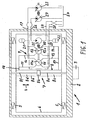
- the vibrator shown in FIG. 1, generally designated 1, has an outer frame 2 forming an action mass, to which a holding element 3 is detachably fastened; This can be designed as a guide fork or as a clamping element and serves to act on a pile not shown.
- the outer frame 2 is supported - in the direction of the oscillatory movements (double arrow 4) - via mechanical spring elements 5 on a support frame 6, which in turn forms a reaction mass.
- the prestressing of the spring elements 5 should be adjustable individually and sensitively, so that irregular vibratory movements of the support frame 6 with respect to the outer frame 2 are avoided.
- the support frame 6 receives a linear drive unit 7 in the form of a synchronous cylinder 8, the cylinder housing 8a of which is attached to the support frame 6 and is divided by a piston 8b into two outwardly sealed cylinder spaces, namely a front cylinder space 8c facing the holding element 3 and a rear cylinder space 8d.
- the piston rod held on the piston 8b - consisting of two rod sections 8e and 8f - is fastened to the outer frame 2 outside the cylinder space 8c or 8d.
- the piston 8b is alternately moved back and forth with the aid of a control 9 with respect to the support frame 6 and transmits the vibrational movements triggered thereby with the interposition of the spring-supported outer frame 2 to the holding element 3 connected to the pile.
- the outer frame 2 is equipped on the side facing away from the holding element 3 (ie in the illustration above) with a coupling element, not shown, via which a detachable connection with a carrier device - for example a supporting frame - can be established.
- the controller 9 has a control rotor 10 rotating at an adjustable speed, which in turn drives two rotary slides 11 and 12; a reversing channel 11a or 12a is formed in each of these.
- the confluence of the lines 17, 18 lies outside the area in which the piston 8b moves back and forth within the cylinder housing 8a in the operating state.
- the rotary slide valves 11 and 12 are further connected, on the one hand, by a pressure line 19 pressurized with working pressure and, on the other hand, by a tank line 20, each of which has a pressure accumulator 21 or 22 connected in parallel with the relevant line as damping.
- the pressure line 19 is outside the outer frame 2 to an energy source in the form of a hydraulic pump 23 with an adjustable delivery rate connected, while the tank line 20 outside the outer frame 2 in passes a tank 24.
- the rotary drive of the control rotor 10, which is designed as a hydraulic motor 25, is connected on the one hand via a supply line 26 to a hydraulic pump 27 with an adjustable delivery rate and on the other hand via a return line 28 to the tank 24.
- a hydraulic pump 27 with an adjustable delivery rate and on the other hand via a return line 28 to the tank 24.
- the rotary slides 11 and 12 are attached to the control rotor 10 such that their control channels 11a and 12a are offset from one another in the circumferential direction of the rotary slides.
- the line 17 is connected to the tank line 20 via the line 13 and the reversing channel 11a, while the line 14 connected in parallel is blocked by the rotary slide valve 12; Accordingly, the front cylinder space 8c is relieved of pressure.
- the line 18 is connected via the line 16 and the reversing channel 12a of the rotary slide 12 to the pressure line 19 pressurized with the working pressure, the line 15 being blocked by the rotary slide 11 at the same time.
- the working pressure is effective within the rear cylinder space 8d, with the result that the piston 8b executes a working stroke in the direction of the supporting element 3 and thereby moves the outer frame 2 with respect to the supporting frame 6 accordingly.
- the piston 8b is alternately driven either in the direction of the support element 3 or in the opposite direction during a rotation angle of 180 °, as a result of which corresponding oscillatory movements of the outer frame 2 and the support element 3 are triggered.
- the pressure accumulators 21 and 22 serve to dampen volume and pressure fluctuations that arise during the orbital movement of the control rotor 10.
- the vibrator 1 can also have multiple parallel cylinders 8 connected in parallel, which simultaneously and moved back and forth in the same direction under the influence of the control 9.
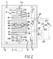
- the embodiment of the subject matter of FIG. 2 differs essentially from the previously described embodiment in that the linear drive unit has a pair of differential cylinders, namely a differential cylinder 30 on the side of the support frame 6 facing the holding element 3 and a differential cylinder 31 on the opposite side of the Support frame 6.
- the piston 30b or 31b which can be displaced in a straight line within a cylinder housing 30a or 31a, carries a piston rod 30c or 31c on one side, to which the outer frame 2 is fastened.
- control system is designed such that, under its action, only one of the two differential cylinders 30 and 31 is driven alternately in the sense of an extension movement of its piston rod 30c and 31c with respect to the support frame 6, while the piston rod of the associated other differential cylinder is also driven without is moved.
- the control 9 is - as already explained with reference to FIG. 1 - with a of the hydraulic motor 25 driven control rotor 10 equipped which the rotary slides 11 and 12 are moved with.
- the line 17 connected to the cylinder space 30d is relieved of pressure via the line 13, the reversing channel 11a of the rotary slide valve 11 and the tank line 20, while the line 14 is blocked by the rotary slide valve 12.
- the line 18 connected to the cylinder space 31d is subjected to working pressure via the line 16, the reversing channel 12a of the rotary slide 12 and the pressure line 19, while the line 15 is blocked by the rotary slide 11. Accordingly, the working pressure is present in the cylinder space 31d, under the influence of which the piston 31b and the piston rod 31c execute an extension movement and thereby also move the outer frame 2 in this direction.
- the pressure-relieved differential cylinder 30 runs along with no drive.
- the rotary slides 11, 12 with the adjoining lines are combined to form a control block 32, to which the differential cylinders 30 and 31 are in turn attached.
- This embodiment can also be modified within the scope of the invention in that the vibrator 1 has a plurality of pairs of differential cylinders, with correspondingly arranged differential cylinders - that is to say on the one hand the differential cylinders on the side facing the holding element 3 and on the other hand the differential cylinders on the side facing away from them - parallel to one another are switched.
- the advantage achieved with the invention is in particular that the novel vibrator - due to the resilient support of the outer frame 2 with respect to the support frame 6 receiving the linear drive unit shows improved vibration behavior and thus an overall increased Economy.
Landscapes
- Engineering & Computer Science (AREA)
- Life Sciences & Earth Sciences (AREA)
- General Life Sciences & Earth Sciences (AREA)
- Mining & Mineral Resources (AREA)
- Paleontology (AREA)
- Civil Engineering (AREA)
- General Engineering & Computer Science (AREA)
- Structural Engineering (AREA)
- Apparatuses For Generation Of Mechanical Vibrations (AREA)
- Placing Or Removing Of Piles Or Sheet Piles, Or Accessories Thereof (AREA)
Abstract
Description
Auf der dem Halteelement gegenüberliegenden Seite ist der Tragrahmen mit einem Befestigungsmittel ausgestattet, über welches er an ein Trägergerät angebaut werden kann.
Dem Differentialzylinder ist ein Steuerrotor zugeordnet, über dessen Rotationsschieber wechselweise die größere oder kleinere (stangenseitige) Kolbenfläche an eine mit Arbeitsdruck beaufschlagte Druckleitung angeschlossen ist, während die andere Kolbenfläche gleichzeitig jeweils über eine Tankleitung drucklos gehalten ist. Durch Verändem der Drehzahl des unabhängig angetriebenen Steuerrotors kann die Schwingungsfrequenz des Differentialzylinders beliebig verändert werden. Darüber hinaus läßt sich die vom Differentialzylinder erzeugte Antriebskraft durch Verändern des von einer Hydraulikpumpe erzeugten Arbeitsdrucks beeinflussen.
Die in Rede stehende Vorveröffentlichung offenbart Ausführungsformen eines mit einer Linearantriebseinheit ausgestatteten Vibrators, bei denen der Steuerrotor nebst Drehantrieb entweder außerhalb des Tragrahmens angeordnet oder in diesen integriert ist.
Der Nachteil des bekannten Vibrators ist darin zu sehen, daß die in dem Tragrahmen abgestützte und zudem als Differentialzylinder ausgebildete Linearantriebseinheit über die zugehörige Kolbenstange unmittelbar auf das Rammgut einwirkt und somit ein wenig befriedigendes Schwingungsverhalten zeigt.
Der Grundgedanke der Erfindung besteht dabei darin, die Linearantriebseinheit - die auch mehrere parallel geschaltete Hydraulikzylinder aufweisen kann - schwingungstechnisch insbesondere von dem Halteelement für das Rammgut abzukoppeln; dementsprechend ist der neuartige Vibrator derart ausgebildet, daß die Linearantriebseinheit nicht mehr unmittelbar auf das Rammgut einwirkt. Konkreter ausgedrückt ist die Linearantriebseinheit ausgangsseitig über die zumindest eine Kolbenstange an einem Außenrahmen befestigt, der sich - relativ zum Tragrahmen beweglich - in Richtung der Schwingungsbewegungen federnd an dem Tragrahmen abstützt, wobei der Außenrahmen einerseits das Halteelement trägt und andererseits das Anbauteil für ein Trägergerät bildet. Abweichend vom Stand der Technik ist also zusätzlich ein Außenrahmen vorhanden, an dem das Halteelement befestigt ist und über den der Vibrator insgesamt in seiner Betriebsstellung gehalten wird, beispielsweise als Anbauteil an einem Traggerüst oder an dem Ausleger eines Baufahrzeugs. Der Tragrahmen bildet dabei mit den an ihm angeordneten Bestandteilen eine Reaktionsmasse, während der Außenrahmen mit den zugehörigen Bestandteilen eine Aktionsmasse darstellt. Beide Massen werden unter Einwirkung der Linearantriebseinheit entgegengesetzt mit wechselnder Bewegungsrichtung kontinuierlich beschleunigt und verzögert.
Unter Umständen ist es zweckmäßig, die Federelemente zur Beeinflussung und Vergleichmäßigung des Schwingungsverhaltens hinsichtlich ihrer Vorspannung einstellbar auszubilden.
Unter "Gleichlaufzylinder" ist dabei ein Hydraulikzylinder zu verstehen, der - unabhängig davon, auf welcher Seite die wirksame Kolbenfläche mit Arbeitsdruck beaufschlagt ist - gleich große Antriebskräfte erzeugt.
Mit anderen Worten ausgedrückt ist die von jedem Gleichlaufzylinder in Richtung auf das Halteelement ausgeübte Antriebskraft ebenso groß wie die nach Umschalten der Druckbeaufschlagung in entgegengesetzter Richtung wirksame Antriebskraft.
Zur Vermeidung einer unerwünschten Beanspruchung wird der neuartige Vibrator im Normalfall derart ausgestattet sein, daß er mehrere gleichartige und parallel geschaltete Gleichlaufzylinder aufweist.
Die Rotationsschieber sind also derart ausgebildet und aufeinander abgestimmt, daß über einen Drehwinkel von 180° des Steuerrotors ein Rotationsschieber die Druckbeaufschlagung einer Kolbenfläche des Gleichlaufzylinders mit Arbeitsdruck bewirkt, während gleichzeitig der andere Rotationsschieber die entgegengerichtete Kolbenfläche durch Aufrechterhalten einer Verbindung mit der Tankleitung druckentlastet.
Nach Überschreiten eines Drehwinkels von 180° ändern sich die Druckverhältnisse in jedem Gleichlaufzylinder dahingehend, daß die bisher druckentlastete Kolbenfläche mit Arbeitsdruck beaufschlagt wird, während der Zylinderraum - welcher der bisher druckbeaufschlagten Kolbenfläche zugeordnet ist - dann mit der Tankleitung verbunden wird.
Auch in diesem Fall sollte der Vibrator zweckmäßig mehrere jeweils paarweise angeordnete Differentialzylinder aufweisen, wobei die in Richtung auf das Halteelement und die in dazu entgegengesetzter Richtung wirksamen Differentialzylinder untereinander jeweils parallel geschaltet sind.
Soweit der Vibrator zusätzlich Druckspeicher (gemäß Anspruch 7) aufweist, können diese im Rahmen der Erfindung ebenfalls in den Tragrahmen integriert sein.
- Fig. 1
- stark schematisiert einen Schaltplan eines Vibrators, dessen Linearantriebseinheit als Gleichlaufzylinder ausgebildet ist, und
- Fig. 2
- das Schemabild eines Vibrators, der als Linearantriebseinheit ein Differentialzylinder-Paar aufweist.
Der Außenrahmen 2 stützt sich - in Richtung der Schwingungsbewegungen (Doppelpfeil 4) gesehen - über mechanische Federelemente 5 an einem Tragrahmen 6 ab, der seinerseits eine Reaktionsmasse bildet. Die Vorspannung der Federelemente 5 sollte einzeln und feinfühlig einstellbar sein, damit ungleichmäßige Schwingungsbewegungen des Tragrahmens 6 bezüglich des Außenrahmens 2 vermieden werden.
Die an dem Kolben 8b gehaltene Kolbenstange - bestehent aus zwei Stangenabschnitten 8e und 8f - ist außerhalb des Zylinderraums 8c bzw. 8d an dem Außenrahmen 2 befestigt.
Der Kolben 8b wird unter Einwirkung einer Steuerung 9 wechselweise bezüglich des Tragrahmens 6 hin und her bewegt und überträgt die dadurch ausgelösten Schwingungsbewegungen unter Zwischenschaltung des federnd abgestützten Außenrahmens 2 auf das mit dem Rammgut verbundene Halteelement 3.
Der Außenrahmen 2 ist auf der von dem Halteelement 3 abgewandten Seite (d. h. in der Darstellung oben) mit einem nicht dargestellten Kupplungselement ausgestattet, über welches eine lösbare Verbindung mit einem Trägergerät - beispielsweise einem Traggerüst - hergestellt werden kann.
Den Rotationsschiebern 11, 12 sind jeweils paarweise parallel geschaltete Leitungen 13, 14 bzw. 15, 16 zugeordnet die über eine Leitung 17 bzw. 18 mit dem vorderen Zylinderraum 8c bzw. mit dem hinteren Zylinderraum 8d in Verbindung stehen. Die Einmündung der Leitungen 17, 18 liegt dabei außerhalb des Bereichs, in dem sich der Kolben 8b im Betriebszustand innerhalb des Zylindergehäuses 8a hin und her bewegt.
An die Rotationsschieber 11 und 12 schließt sich weiterhin einerseits eine mit Arbeitsdruck beaufschlagte Druckleitung 19 und andererseits eine Tankleitung 20 an, die als Dämpfung jeweils einen zur betreffenden Leitung parallel geschalteten Druckspeicher 21 bzw. 22 aufweist.
Durch Verstellung der Fördermenge der Pumpen 23 und 27 kann die von der Linearantriebseinheit 7 erzeugte Antriebskraft bzw. die auf den Außenrahmen 2 einwirkende Schwingungsfrequenz unabhängig und beliebig verändert werden.
In dem angedeuteten Betriebszustand ist die Leitung 17 über die Leitung 13 und den Umsteuerkanal 11a an die Tankleitung 20 angeschlossen, während die parallel geschaltete Leitung 14 durch den Rotationsschieber 12 blockiert ist; dementsprechend ist der vordere Zylinderraum 8c druckentlastet.
Im Gegensatz dazu steht die Leitung 18 über die Leitung 16 und den Umsteuerkanal 12a des Rotationsschiebers 12 mit der mit dem Arbeitsdruck beaufschlagten Druckleitung 19 in Verbindung, wobei gleichzeitig die Leitung 15 durch den Rotationsschieber 11 blockiert ist. Auf Grund dessen ist innerhalb des hinteren Zylinderraums 8d der Arbeitsdruck wirksam mit der Folge, daß der Kolben 8b einen Arbeitshub in Richtung auf das Tragelement 3 ausführt und dabei den Außenrahmen 2 bezüglich des Tragrahmens 6 entsprechend bewegt. Abhängig von der Drehstellung des Steuerrotors 10 und der sich daraus ergebenden Drehlage der Umsteuerkanäle 11a und 12a wird der Kolben 8b also während eines Drehwinkels von 180° wechselweise entweder in Richtung auf das Tragelement 3 oder in dazu entgegengesetzter Richtung angetrieben, wodurch entsprechende Schwingungsbewegungen des Außenrahmens 2 und des Tragelements 3 ausgelöst werden.
Die Druckspeicher 21 und 22 dienen dabei dazu, bei der Umlaufbewegung des Steuerrotors 10 entstehende Mengen- und Druckschwankungen zu dämpfen.
Der innerhalb eines Zylindergehäuses 30a bzw. 31a geradlinig verschiebbare Kolben 30b bzw. 31b trägt einseitig jeweils eine Kolbenstange 30c bzw. 31c, an welcher der Außenrahmen 2 befestigt ist.
Die Steuerung ist in diesem Fall derart ausgebildet, daß unter ihrer Einwirkung wechselweise jeweils nur einer der beiden Differentialzylinder 30 bzw. 31 im Sinne einer Ausfahrbewegung seiner Kolbenstange 30c bzw. 31c bezüglich des Tragrahmens 6 angetrieben ist, während die Kolbenstange des zugehörigen anderen Differentialzylinders antriebslos mit bewegt wird.
Im Gegensatz dazu ist die mit dem Zylinderraum 31d verbundene Leitung 18 über die Leitung 16, den Umsteuerkanal 12a des Rotationsschiebers 12 und die Druckleitung 19 mit Arbeitsdruck beaufschlagt, während die Leitung 15 durch den Rotationsschieber 11 blockiert ist. Dementsprechend liegt in dem Zylinderraum 31d der Arbeitsdruck an, unter dessen Einwirkung der Kolben 31b nebst Kolbenstange 31c eine Ausfahrbewegung ausführt und dabei den Außenrahmen 2 in dieser Richtung mit bewegt. Der druckentlastete Differentialzylinder 30 läuft währenddessen antriebslos mit.
Dieser Zustand bleibt so lange erhalten, bis - nach Durchführen einer
Drehbewegung des Steuerrotors 10 um 180° - die Druckverhältnisse in den Differentialzylinder 30 und 31 eine Umkehrung erfahren, d. h. nach einer entsprechenden Drehbewegung des Steuerrotors 10 und der Rotationsschieber 11, 12 wird anschließend der Zylinderraum 30d mit Arbeitsdruck beaufschlagt, während gleichzeitig der Zylinderraum 31d drucklos geschaltet wird. Dementsprechend führt der nunmehr angetriebene Kolben 30b bezüglich des Zylindergehäuses 30a eine Ausfahrbewegung aus und bewegt den Außenrahmen 2 nebst Halteelement 3 bezüglich des Tragrahmens 6 gleichsinnig mit.
Auch diese Ausführungsform kann im Rahmen der Erfindung dahingehend abgeändert sein, daß der Vibrator 1 mehrere Differentialzylinder-Paare aufweist, wobei entsprechend angeordnete Differentialzylinder - d. h. einerseits die Differentialzylinder auf der dem Halteelemt 3 zugewandten Seite und andererseits die Differentialzylinder auf der davon abgewandten Seite - untereinander parallel geschaltet sind.
Claims (9)
- Vibrator zur Einwirkung auf Rammgut, wie Spundbohlen, Pfähle, Kanaldielen, mit einer Linearantriebseinheit (7) in Form zumindest eines Hydraulikzylinders, dessen zumindest eine Kolbenstange (8e, f; 30c, d) unter Einwirkung einer Steuerung (9) bezüglich eines die Linearantriebseinheit aufnehmenden Tragrahmens (6) geradlinig wechselweise hin und her bewegt wird und dabei ihre Schwingungsbewegungen auf ein mit dem Rammgut verbundendes Halteelement (3) überträgt, wobei die mittels der Linearantriebseinheit erzeugte Schwingungsfrequenz und die von ihr ausgehende Antriebskraft veränderbar sind,
dadurch gekennzeichnet, daß die Linearantriebseinheit (7) ausgangsseitig über die zumindest eine Kolbenstange (8e, f; 30c, d) an einem Außenrahmen (2) befestigt ist, der sich - relativ zum Tragrahmen (6) beweglich - in Richtung der Schwingungsbewegungen (Doppelpfeil 4) federnd an dem Tragrahmen (6) abstützt, wobei der Außenrahmen (2) einerseits das Halteelement (3) trägt und andererseits das Anbauteil für ein Trägergerät bildet. - Vibrator nach Anspruch 1, dadurch gekennzeichnet, daß die Linearantriebseinheit (7) zumindest einen Gleichlaufzylinder (8) aufweist, dessen Kolbenstange (8e, f) jeweils sowohl auf der dem Halteelement (3) zugewandten Seite als auch auf der davon abgewandten Seite an dem Außenrahmen (2) befestigt ist.
- Vibrator nach Anspruch 2, dadurch gekennzeichnet, daß der zumindest eine Gleichlaufzylinder (8) über die Steuerung (9) wechselweise derart angetrieben ist, daß seine Kolbenstange (8e, f) bezüglich des Tragrahmens (6) entweder eine Ausfahrbewegung in Richtung auf das Halteelement (3) oder in dazu entgegengesetzter Richtung ausführt.
- Vibrator nach Anspruch 2 oder 3, dadurch gekennzeichnet, daß die Steuerung (9) einen mit einstellbarer Drehzahl umlaufenden Steuerrotor (10) mit zwei Rotationsschiebern (11, 12) aufweist, über welche jeweils die sich gegenüberliegenden Kolbenflächen jedes Gleichlaufzylinders (8) - abhängig von der Drehstellung des Steuerrotors (10) - wechselweise einerseits mittels einer Tankleitung (20) druckentlastet bzw. andererseits mittels einer Druckleitung (19) mit Arbeitsdruck beaufschlagt sind.
- Vibrator nach Anspruch 1, dadurch gekennzeichnet, daßdie Linearantriebseinheit (7) zumindest ein Paar Differentialzylinder (30, 31) aufweist, deren Kolbenstange (30c bzw. 31c) entweder auf der dem Halteelement (3) zugewandten Seite oder auf der davon abgewandten Seite an dem Außenrahmen (2) befestigt ist, wobei unter Einwirkung der Steuerung (9) wechselweise jeweils nur einer der beiden Differentialzylinder (30, 31) jedes Paares im Sinne einer Ausfahrbewegung seiner Kolbenstange (30c bzw. 31c) bezüglich des Tragrahmens (2) angetrieben ist, während die Kolbenstange des zugehörigen anderen Differentialzylinders antriebslos mit bewegt wird.
- Vibrator nach Anspruch 5, dadurch gekennzeichnet, daß die Steuerung (9) einen mit einstellbarer Drehzahl umlaufenden Steuerrotor (10) mit zwei Rotationsschiebem (11,12) aufweist, über welche die sich gegenüberliegenden Kolbenflächen jedes Differentialzylinder-Paares (30, 31) - abhängig von der Drehstellung des Steuerrotors (10) - wechselweise entweder mittels einer Tankleitung (20) druckentlastet oder mittels einer Druckleitung (19) mit Arbeitsdruck beaufschlagt sind.
- Vibrator nach Anspruch 4 oder 6, dadurch gekennzeichnet, daß die Tankleitung (20) und die Druckleitung (19) als Dämpfung jeweils einen dazu parallel geschalteten Druckspeicher (22 bzw. 21) aufweisen.
- Vibrator nach Anspruch 4 oder 6, dadurch gekennzeichnet, daß der Steuerrotor (10) nebst Drehantrieb (25) und die Rotationsschieber (11, 12) Bestandteil des Tragrahmens (6) sind.
- Vibrator nach Anspruch 8, dadurch gekennzeichnet, daß der Drehantrieb als Hydraulikmotor (25) ausgebildet und mittels einer Hydraulikpumpe (27) mit einstellbarer Fördermenge angetrieben ist.
Applications Claiming Priority (2)
| Application Number | Priority Date | Filing Date | Title |
|---|---|---|---|
| DE2000130859 DE10030859A1 (de) | 2000-06-23 | 2000-06-23 | Vibrator mit einer Linearantriebseinheit zur Einwirkung auf Rammgut |
| DE10030859 | 2000-06-23 |
Publications (3)
| Publication Number | Publication Date |
|---|---|
| EP1167632A2 true EP1167632A2 (de) | 2002-01-02 |
| EP1167632A3 EP1167632A3 (de) | 2002-07-17 |
| EP1167632B1 EP1167632B1 (de) | 2005-12-07 |
Family
ID=7646691
Family Applications (1)
| Application Number | Title | Priority Date | Filing Date |
|---|---|---|---|
| EP20010114622 Expired - Lifetime EP1167632B1 (de) | 2000-06-23 | 2001-06-19 | Vibrator mit einer Linearantriebseinheit |
Country Status (2)
| Country | Link |
|---|---|
| EP (1) | EP1167632B1 (de) |
| DE (2) | DE10030859A1 (de) |
Cited By (1)
| Publication number | Priority date | Publication date | Assignee | Title |
|---|---|---|---|---|
| WO2005056201A1 (de) * | 2003-12-14 | 2005-06-23 | GEDIB Ingenieurbüro und Innovationsberatung GmbH | Rammvibrator für rammgut |
Citations (1)
| Publication number | Priority date | Publication date | Assignee | Title |
|---|---|---|---|---|
| DE2410385A1 (de) | 1974-03-05 | 1975-09-18 | Mueller Ludwig | Verfahren und vorrichtung zum rammen oder ziehen von rammkoerpern, wie z.b. spundbohlen, pfaehlen oder dergleichen |
Family Cites Families (5)
| Publication number | Priority date | Publication date | Assignee | Title |
|---|---|---|---|---|
| FR1544841A (fr) * | 1967-09-28 | 1968-11-08 | Vide Soc Gen Du | Perfectionnements aux systèmes de suspension, des machines hydrauliques vibrantes, notamment pour le fonçage des pieux |
| US4178838A (en) * | 1977-11-03 | 1979-12-18 | Conoco, Inc. | Oil porting system for dual cylinder vibrator |
| US4301874A (en) * | 1979-11-08 | 1981-11-24 | Keichiro Majima | Pile or sheet-pile driver |
| DE3608732A1 (de) * | 1986-03-15 | 1987-09-24 | Hutz Horst Guenter | Vorrichtung zum einbringen und/oder herausziehen eines bauprofils |
| US5725329A (en) * | 1996-05-08 | 1998-03-10 | Chelminski; Stephen | Method, system and apparatus for driving and pulling pilings |
-
2000
- 2000-06-23 DE DE2000130859 patent/DE10030859A1/de not_active Withdrawn
-
2001
- 2001-06-19 DE DE50108278T patent/DE50108278D1/de not_active Expired - Fee Related
- 2001-06-19 EP EP20010114622 patent/EP1167632B1/de not_active Expired - Lifetime
Patent Citations (1)
| Publication number | Priority date | Publication date | Assignee | Title |
|---|---|---|---|---|
| DE2410385A1 (de) | 1974-03-05 | 1975-09-18 | Mueller Ludwig | Verfahren und vorrichtung zum rammen oder ziehen von rammkoerpern, wie z.b. spundbohlen, pfaehlen oder dergleichen |
Cited By (1)
| Publication number | Priority date | Publication date | Assignee | Title |
|---|---|---|---|---|
| WO2005056201A1 (de) * | 2003-12-14 | 2005-06-23 | GEDIB Ingenieurbüro und Innovationsberatung GmbH | Rammvibrator für rammgut |
Also Published As
| Publication number | Publication date |
|---|---|
| DE50108278D1 (de) | 2006-01-12 |
| EP1167632A3 (de) | 2002-07-17 |
| EP1167632B1 (de) | 2005-12-07 |
| DE10030859A1 (de) | 2002-01-03 |
Similar Documents
| Publication | Publication Date | Title |
|---|---|---|
| AT411874B (de) | Siebvorrichtung | |
| EP0135479B1 (de) | Vorrichtung zum Rammen und Ziehen | |
| DE2710920C2 (de) | Vibrationsgedämpfter Schlagmechanismus mit Druckmittelantrieb | |
| DE1204920B (de) | Sieb- oder Foerdermaschine | |
| DE69722729T2 (de) | Reibschweissgerät | |
| DE69934696T2 (de) | Verstellbarer exzenterschwinghammer | |
| WO2000061344A1 (de) | Innenrüttelvorrichtung mit veränderbarer schwingungsamplitude | |
| DE1660783B2 (de) | Vorrichtung zum nadeln von faservliesen o.dgl. | |
| DE202005006059U1 (de) | Anbauverdichter mit einstellbarer Erregermasse | |
| DE2231106C3 (de) | Hydraulischer Schwingungserreger für Vibrationsverdichter | |
| EP3556478B1 (de) | Vibrationsantreiben mit einem mehrflächenzylinder | |
| EP1167632B1 (de) | Vibrator mit einer Linearantriebseinheit | |
| DE10308094A1 (de) | Vorrichtung und Verfahren zur Prüfung innendruckbelasteter Bauteile | |
| DE2114282A1 (de) | Vibrationsantrieb fuer Werkzeugaggregate einer Gleisbaumaschine | |
| DE8808036U1 (de) | Mechanische Säge | |
| DE2400554C2 (de) | Verfahren und hydraulische Vorrichtung zum vibrierenden Bearbeiten von Materialien | |
| DD276125A5 (de) | Pulshydraulik-antriebssystem | |
| DE19532570A1 (de) | Verfahren und Vorrichtung zum Schneiden von mit wenigstens einem Draht oder einem anderen Schneidmittel zu schneidendem Material | |
| AT502044B1 (de) | Vorrichtung zum nadeln eines vlieses | |
| EP0850364B1 (de) | Vorrichtung zum ansteuern eines hydrostatischen antriebes | |
| DE2120231C3 (de) | Vorrichtung zum Antrieb eines Stopf aggregates in einer Stopfmaschine für den Gleisbau | |
| DE4340699A1 (de) | Vorrichtung zur dynamischen Bodenverdichtung | |
| DE2425953A1 (de) | Niedrig bauende siebmaschine | |
| DE2120045C3 (de) | Vorrichtung zur Erzeugung von Schwingungen mit einem hydraulischen Arbeitszylinder | |
| DE102005041915B4 (de) | Vibrationsförderer |
Legal Events
| Date | Code | Title | Description |
|---|---|---|---|
| PUAI | Public reference made under article 153(3) epc to a published international application that has entered the european phase |
Free format text: ORIGINAL CODE: 0009012 |
|
| AK | Designated contracting states |
Kind code of ref document: A2 Designated state(s): AT BE CH CY DE DK ES FI FR GB GR IE IT LI LU MC NL PT SE TR |
|
| AX | Request for extension of the european patent |
Free format text: AL;LT;LV;MK;RO;SI |
|
| PUAL | Search report despatched |
Free format text: ORIGINAL CODE: 0009013 |
|
| AK | Designated contracting states |
Kind code of ref document: A3 Designated state(s): AT BE CH CY DE DK ES FI FR GB GR IE IT LI LU MC NL PT SE TR |
|
| AX | Request for extension of the european patent |
Free format text: AL;LT;LV;MK;RO;SI |
|
| 17P | Request for examination filed |
Effective date: 20030117 |
|
| AKX | Designation fees paid |
Designated state(s): DE FR IT NL |
|
| RAP1 | Party data changed (applicant data changed or rights of an application transferred) |
Owner name: THYSSENKRUPP GFT TIEFBAUTECHNIK GMBH |
|
| GRAP | Despatch of communication of intention to grant a patent |
Free format text: ORIGINAL CODE: EPIDOSNIGR1 |
|
| GRAS | Grant fee paid |
Free format text: ORIGINAL CODE: EPIDOSNIGR3 |
|
| GRAA | (expected) grant |
Free format text: ORIGINAL CODE: 0009210 |
|
| AK | Designated contracting states |
Kind code of ref document: B1 Designated state(s): DE FR IT NL |
|
| REF | Corresponds to: |
Ref document number: 50108278 Country of ref document: DE Date of ref document: 20060112 Kind code of ref document: P |
|
| PGFP | Annual fee paid to national office [announced via postgrant information from national office to epo] |
Ref country code: IT Payment date: 20060630 Year of fee payment: 6 |
|
| ET | Fr: translation filed | ||
| PLBE | No opposition filed within time limit |
Free format text: ORIGINAL CODE: 0009261 |
|
| STAA | Information on the status of an ep patent application or granted ep patent |
Free format text: STATUS: NO OPPOSITION FILED WITHIN TIME LIMIT |
|
| 26N | No opposition filed |
Effective date: 20060908 |
|
| PG25 | Lapsed in a contracting state [announced via postgrant information from national office to epo] |
Ref country code: NL Free format text: LAPSE BECAUSE OF NON-PAYMENT OF DUE FEES Effective date: 20070101 |
|
| PG25 | Lapsed in a contracting state [announced via postgrant information from national office to epo] |
Ref country code: DE Free format text: LAPSE BECAUSE OF NON-PAYMENT OF DUE FEES Effective date: 20070103 |
|
| NLV4 | Nl: lapsed or anulled due to non-payment of the annual fee |
Effective date: 20070101 |
|
| REG | Reference to a national code |
Ref country code: FR Ref legal event code: ST Effective date: 20070228 |
|
| PG25 | Lapsed in a contracting state [announced via postgrant information from national office to epo] |
Ref country code: FR Free format text: LAPSE BECAUSE OF NON-PAYMENT OF DUE FEES Effective date: 20060630 |
|
| PG25 | Lapsed in a contracting state [announced via postgrant information from national office to epo] |
Ref country code: IT Free format text: LAPSE BECAUSE OF NON-PAYMENT OF DUE FEES Effective date: 20070619 |