EP1162089B1 - Vehicle tire air pressure detecting device and cast wheel for mounting the device - Google Patents
Vehicle tire air pressure detecting device and cast wheel for mounting the device Download PDFInfo
- Publication number
- EP1162089B1 EP1162089B1 EP01113768A EP01113768A EP1162089B1 EP 1162089 B1 EP1162089 B1 EP 1162089B1 EP 01113768 A EP01113768 A EP 01113768A EP 01113768 A EP01113768 A EP 01113768A EP 1162089 B1 EP1162089 B1 EP 1162089B1
- Authority
- EP
- European Patent Office
- Prior art keywords
- air pressure
- tire
- detecting device
- rim
- section
- Prior art date
- Legal status (The legal status is an assumption and is not a legal conclusion. Google has not performed a legal analysis and makes no representation as to the accuracy of the status listed.)
- Expired - Lifetime
Links
- 239000011324 bead Substances 0.000 claims description 19
- 230000002452 interceptive effect Effects 0.000 claims description 9
- 230000002093 peripheral effect Effects 0.000 claims description 8
- 239000000725 suspension Substances 0.000 description 5
- DOSMHBDKKKMIEF-UHFFFAOYSA-N 2-[3-(diethylamino)-6-diethylazaniumylidenexanthen-9-yl]-5-[3-[3-[4-(1-methylindol-3-yl)-2,5-dioxopyrrol-3-yl]indol-1-yl]propylsulfamoyl]benzenesulfonate Chemical compound C1=CC(=[N+](CC)CC)C=C2OC3=CC(N(CC)CC)=CC=C3C(C=3C(=CC(=CC=3)S(=O)(=O)NCCCN3C4=CC=CC=C4C(C=4C(NC(=O)C=4C=4C5=CC=CC=C5N(C)C=4)=O)=C3)S([O-])(=O)=O)=C21 DOSMHBDKKKMIEF-UHFFFAOYSA-N 0.000 description 2
- 238000001514 detection method Methods 0.000 description 2
- 230000005540 biological transmission Effects 0.000 description 1
- 230000000694 effects Effects 0.000 description 1
- 239000000446 fuel Substances 0.000 description 1
Images

Classifications
-
- B—PERFORMING OPERATIONS; TRANSPORTING
- B60—VEHICLES IN GENERAL
- B60C—VEHICLE TYRES; TYRE INFLATION; TYRE CHANGING; CONNECTING VALVES TO INFLATABLE ELASTIC BODIES IN GENERAL; DEVICES OR ARRANGEMENTS RELATED TO TYRES
- B60C23/00—Devices for measuring, signalling, controlling, or distributing tyre pressure or temperature, specially adapted for mounting on vehicles; Arrangement of tyre inflating devices on vehicles, e.g. of pumps or of tanks; Tyre cooling arrangements
- B60C23/02—Signalling devices actuated by tyre pressure
- B60C23/04—Signalling devices actuated by tyre pressure mounted on the wheel or tyre
- B60C23/0491—Constructional details of means for attaching the control device
- B60C23/0494—Valve stem attachments positioned inside the tyre chamber
-
- B—PERFORMING OPERATIONS; TRANSPORTING
- B60—VEHICLES IN GENERAL
- B60B—VEHICLE WHEELS; CASTORS; AXLES FOR WHEELS OR CASTORS; INCREASING WHEEL ADHESION
- B60B21/00—Rims
- B60B21/02—Rims characterised by transverse section
- B60B21/026—Rims characterised by transverse section the shape of rim well
-
- B—PERFORMING OPERATIONS; TRANSPORTING
- B60—VEHICLES IN GENERAL
- B60B—VEHICLE WHEELS; CASTORS; AXLES FOR WHEELS OR CASTORS; INCREASING WHEEL ADHESION
- B60B21/00—Rims
- B60B21/02—Rims characterised by transverse section
- B60B21/04—Rims characterised by transverse section with substantially radial flanges
-
- B—PERFORMING OPERATIONS; TRANSPORTING
- B60—VEHICLES IN GENERAL
- B60B—VEHICLE WHEELS; CASTORS; AXLES FOR WHEELS OR CASTORS; INCREASING WHEEL ADHESION
- B60B21/00—Rims
- B60B21/12—Appurtenances, e.g. lining bands
-
- B—PERFORMING OPERATIONS; TRANSPORTING
- B60—VEHICLES IN GENERAL
- B60C—VEHICLE TYRES; TYRE INFLATION; TYRE CHANGING; CONNECTING VALVES TO INFLATABLE ELASTIC BODIES IN GENERAL; DEVICES OR ARRANGEMENTS RELATED TO TYRES
- B60C23/00—Devices for measuring, signalling, controlling, or distributing tyre pressure or temperature, specially adapted for mounting on vehicles; Arrangement of tyre inflating devices on vehicles, e.g. of pumps or of tanks; Tyre cooling arrangements
- B60C23/005—Devices specially adapted for special wheel arrangements
- B60C23/006—Devices specially adapted for special wheel arrangements having two wheels only
-
- B—PERFORMING OPERATIONS; TRANSPORTING
- B60—VEHICLES IN GENERAL
- B60C—VEHICLE TYRES; TYRE INFLATION; TYRE CHANGING; CONNECTING VALVES TO INFLATABLE ELASTIC BODIES IN GENERAL; DEVICES OR ARRANGEMENTS RELATED TO TYRES
- B60C23/00—Devices for measuring, signalling, controlling, or distributing tyre pressure or temperature, specially adapted for mounting on vehicles; Arrangement of tyre inflating devices on vehicles, e.g. of pumps or of tanks; Tyre cooling arrangements
- B60C23/02—Signalling devices actuated by tyre pressure
- B60C23/04—Signalling devices actuated by tyre pressure mounted on the wheel or tyre
- B60C23/0408—Signalling devices actuated by tyre pressure mounted on the wheel or tyre transmitting the signals by non-mechanical means from the wheel or tyre to a vehicle body mounted receiver
Definitions
- the present invention relates to a vehicular cast wheel according to the preamble part of claim 1.
- Document DE 196 26 446 A1 discloses a generic vehicular cast wheel having a tire air pressure sensor, which is fixed by clamp means in two recesses of a rim.
- the recesses are formed in passages between tire seat sections and a bed section of the rim.
- an object of the present invention is to prevent bead sections of a tire from interfering with an on vehicle tire air pressure detecting device when assembling the tire on a cast wheel, or removing the tire from the cast wheel.
- Claim 2 is characterized in that the air pressure sensor is formed in a shape of a curve along an inner side surface of the rim.
- the air pressure sensor By constituting the air pressure sensor in the shape of the curve along the inner side surface of the rim, and by eliminating a projecting section of the air pressure sensor to the tire side, when the tire is assembled on the cast wheel, or is removed from the cast wheel, the bead sections of the tire are prevented from interfering with the air pressure sensor, and damaging of the air pressure sensor is prevented.
- Claim 3 is characterized by a weight section for being easily balanced with the air pressure sensor at a position shifted at an angle of 180° to a peripheral direction from a position where the air pressure sensor is mounted on the rim, where in the weight section is integrally molded with the rim.
- a cast wheel By being integrally molded a weight section with the rim, a cast wheel is easily in balance, a necessity to mount or to affix specific weight to the cast wheel in an attempt to be in a good wheel balance is eliminated, and workability is improved.
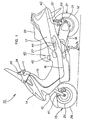
- Fig. 1 shows a side elevation view of a motorcycle provided with an on vehicle tire air pressure detecting device relating to the present invention
- a motorcycle 10 as a vehicle is constituted of a handlebar 11, a front fork 12 and a front wheel 13 mounted freely steerably on a lower section of the handlebar 11, a front cover 14 and a front inner cover 15 for covering a lower section of the handlebar 11 and an upper section of the front fork 12, a floor step 16 arranged in a rearward of a lower section of the front cover 14, a body cover 17 continued upward at a rear section of the floor step 16, a power unit 18 extending to a rearward from an inner side of the body cover 17, a rear wheel 21 mounted to a rearward of the power unit 18, and an air suspension device 22 respectively suspended between a rear end section of the power unit 18 and a vehicular body frame, not illustrated, inside the body cover 17.
- numeral 24 denotes a meter cover mounted on a handlebar 11
- numerals 25 and 26 denote a wheel and a tire of the front wheel 13
- numeral 27 denotes a carburetor for supplying fuel to an engine constituting the power unit 18
- numerals 31 and 32 denote a wheel and a tire of the rear wheel 21
- numeral 33 denotes a seat.
- An on vehicle tire air pressure detecting device 40 (hereinafter referred to as "air pressure detecting device 40") of the present invention, is constituted of a tire air pressure detecting device 41 as an air pressure sensor for a front wheel for detecting an air pressure of the tire 26 by mounting the device 41 on the wheel 25 of the front wheel 13, a tire air pressure detecting device 42 as an air pressure sensor for a rear wheel for detecting an air pressure of the tire 32 by mounting the device 42 on the wheel 31 of the rear wheel 21, an air suspension air pressure detecting device 43 mounted on the air suspension device 22, for example, an engine output adjusting device 44 for adjusting an opening degree of a throttle by mounting the device 44 on a carburetor 27, a control device 45 by operating a warning device, not illustrated, by receiving a signal transmitted from the tire air pressure detecting devices 41 and 42, and the air suspension air pressure detecting device 43, and controlling the engine output adjusting device 44, a display device 46 for displaying the air pressure of the tire 26 of the front wheel 13, the air pressure of the tire 32 of the rear
- the control device 45 for example, is arranged downward the seat 33 and the display device 46, for example, is mounted on a meter cover 24.
- Fig. 2 shows a first sectional view illustrating a mounting state of a tire air pressure detecting device 41 in an air pressure detecting device relating to the present invention, and with regard to the tire air pressure detecting device 41 for the front wheel will be explained.
- a tire air pressure detecting device 42 for the rear wheel since the structure is the same as the tire air pressure detecting device 41 for the front wheel, the explanation in Fig. 2 and afterward will be abbreviated.
- the tire air pressure detecting device 41 is constituted of a detecting device main body 51, and a tire valve 52 mounted on the detecting device main body 51 for the purpose of opening only when supplying air to inside the tire 26 (refer to Fig. 1), and for the purpose of being closed so as not air supplied to inside the tire 26 being flowed out to an outer section, the detecting device main body 51 is arranged on a recessed section 54 provided on a bottom of a rim 53, the tire valve 52 is inserted into a valve inserting hole 55 opened on the bottom of the rim 53, a nut 57 is threaded into an external thread section 56 provided on an outer peripheral surface of the tire valve 52, and the tire air pressure detecting device 41 is mounted on the wheel 25.
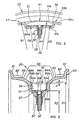
- Fig. 3 shows a second sectional view illustrating the mounting state of the tire air pressure detecting device in the air pressure detecting device relating to the present invention.
- the wheel 25 is constituted of flange sections 61, bead seat sections 62 provided on inner sides of these flange sections 61, hump sections 63 protuberantly molded on an inner side of the these bead seat sections 62, a rim drop section 64 dented between respective these hump sections 63, and the recessed section 54 described above provided in this rim drop section 64.
- the bead seat section 62 is a portion holding a bead section of the tire 26 (refer to Fig. 1).
- the hump section 63 is a projecting section in a shape of a ring for preventing the tire 26 from coming off from the bead seat section 62 of the wheel 25.
- the rim drop section 64 is a portion for facilitating attachment /detachment of the tire 26 by deeply dropping the section 64.
- the tire air pressure detecting device 41 is a device mounted on an outer surface 51a of the detection device main body 51 on the rim 53 being an inner side by only an amount d from a bottom surface (described later) of the rim drop section 64.
- numeral 67 denotes a seal member for preventing air from leaking to an outer section from an air chamber inside the tire 26
- numeral 68 denotes a communicating hole (blocked by valve element not illustrated) provided inside a tire valve 52 for communicating an inside /outside of the tire 26.
- the bead sections of the tire 26 are possible to be prevented from interfering with the detecting device main body 51, and the damaging of detecting device main body 51 is prevented.
- a distance (radius) from the center of the wheel 25 to the bottom surface 64c is set as R1
- a distance (radius) from the center of the wheel 25 of the bottom surface 54b of the recessed section 54 is set as R2.
- the detecting device main body 51 is a body formed in a shape of a curve along an inner side surface 53a (that is, a total surfaces added a bottom surface 64c of the rim drop section 64 to a bottom surface 54b of the recessed section 54) of the rim 53.
- the radius R4 of the outer surface 51a of the detecting device main body 51 is set smaller than the radius R1 of the bottom surface 64c of the rim drop section 64 (refer to Fig. 3) of the wheel of 10 inch size of the minimum diameter, even if a tire air pressure detecting mean 41 is mounted on any wheels of 10 inch - 19 inch size, on an outer surface 51a of the detecting device main body 51 is not protruded on outside from the bottom surface 64c of the rim drop section 64. That is, a relationship of R4 ⁇ R1 is satisfied.
- the detecting device main body 51 is a body contrived in a shape of a curve along the inner side surface 53a of the rim 53.
- a projecting section to a tire 26 (refer to Fig. 1) side of the detecting device main body 51 can be eliminated, and when the tire 26 is assembled on the wheel 25 or the tire 26 is removed from the wheel 25, the bead sections of the tire 26 is prevented from interfering with the detecting device main body 51 and damaging of the detecting device main body 51 is prevented.
- Fig. 4 (a) and Fig. 4 (b) show a view explaining a wheel mounted with the tire air pressure detecting device relating to the present invention
- Fig. 4 (a) shows a side elevation view
- Fig. 4 (b) shows a sectional view taken on line b - b.
- the wheel 25 is contrived to be integrally molded a weight section 69 for being balanced with the tire air pressure detecting device 41 with the rim 53 at a position shifted at an angle of 180° in a peripheral direction from a position mounted with the tire air pressure detecting device 41 (refer to Fig. 3) on the rim 53, that is, from the recessed section 54 (refer to Fig. 3).
- Fig. 4 (b) illustrates the weight section 69 provided by being projected on a wheel center side of the rim 53.
- the weight section 69 for being balanced with the tire air pressure detecting device 41 is integrally molded with the rim 53 at the position shifted an angle of 180° in a peripheral direction from the position mounted with the tire air pressure detecting device 41 on the rim 53.
- the tire air pressure detecting device 41 for the front wheel and the tire air pressure detecting device 42 for the rear wheel explained in an embodiment of the present invention may well be the same dimension with each other or may be differed from each other according to the size of the tire.
- the tire air pressure detecting device 40 can be applied to not necessarily the motorcycle, but to a three-wheeled vehicle or to a four-wheeled vehicle.
- the present invention exhibits the following effects according to the constitution above.
- the bead sections of the tire are capable of being prevented from interfering with the air pressure sensor, and damaging of the air pressure sensor is prevented.
- an air pressure sensor is formed in a shape of a curve along an inner side surface of a rim, a projecting section to a tire side of the air pressure sensor can be eliminated, when the tire is assembled to a cast wheel, or when the tire is removed from the cast wheel, the bead sections of the tire are prevented from interfering with the air pressure sensor, and damaging of the air pressure sensor is prevented.
- a weight section is integrally molded with the rim for being balanced with an air pressure sensor at a position shifted at an angle of 180° in a peripheral direction from a position where the air pressure sensor is mounted on a rim, a cast wheel can be easily in balance, a necessity to mount or to affix specific weight in an attempt to be in a good wheel balance is eliminated, workability is improved.
- a rim drop section 64 dented in a shape of a ring is provided on an inner side of a bead seat section 62 of a rim 53 for holding a bead section of a tire, further, a recessed section 54 is provided on this rim drop section 64, and to this recessed section 54 a detecting device main body 51 of a tire air pressure detecting device 41 is accommodated.
Landscapes
- Engineering & Computer Science (AREA)
- Mechanical Engineering (AREA)
- Measuring Fluid Pressure (AREA)
Applications Claiming Priority (2)
| Application Number | Priority Date | Filing Date | Title |
|---|---|---|---|
| JP2000169342A JP4516187B2 (ja) | 2000-06-06 | 2000-06-06 | 車載用タイヤ空気圧検知装置及び同装置取付用キャストホイール |
| JP2000169342 | 2000-06-06 |
Publications (3)
| Publication Number | Publication Date |
|---|---|
| EP1162089A2 EP1162089A2 (en) | 2001-12-12 |
| EP1162089A3 EP1162089A3 (en) | 2004-02-11 |
| EP1162089B1 true EP1162089B1 (en) | 2006-01-25 |
Family
ID=18672218
Family Applications (1)
| Application Number | Title | Priority Date | Filing Date |
|---|---|---|---|
| EP01113768A Expired - Lifetime EP1162089B1 (en) | 2000-06-06 | 2001-06-05 | Vehicle tire air pressure detecting device and cast wheel for mounting the device |
Country Status (6)
| Country | Link |
|---|---|
| US (1) | US6725711B2 (enExample) |
| EP (1) | EP1162089B1 (enExample) |
| JP (1) | JP4516187B2 (enExample) |
| AU (1) | AU778958B2 (enExample) |
| DE (1) | DE60116817T2 (enExample) |
| ES (1) | ES2257358T3 (enExample) |
Families Citing this family (11)
| Publication number | Priority date | Publication date | Assignee | Title |
|---|---|---|---|---|
| JP4611537B2 (ja) * | 2000-06-09 | 2011-01-12 | 本田技研工業株式会社 | 車載用タイヤ空気圧検知装置 |
| US8266465B2 (en) | 2000-07-26 | 2012-09-11 | Bridgestone Americas Tire Operation, LLC | System for conserving battery life in a battery operated device |
| US7161476B2 (en) * | 2000-07-26 | 2007-01-09 | Bridgestone Firestone North American Tire, Llc | Electronic tire management system |
| JP4040488B2 (ja) | 2003-02-12 | 2008-01-30 | 本田技研工業株式会社 | タイヤ空気圧検知装置の取付構造 |
| JP4569309B2 (ja) * | 2004-07-30 | 2010-10-27 | トヨタ自動車株式会社 | 車輪 |
| US20060117545A1 (en) * | 2004-12-08 | 2006-06-08 | Trw Automotive U.S. Llc | Method of securing a tire-based unit of a tire condition sensing system to a rim and an associated apparatus |
| WO2011030405A1 (ja) * | 2009-09-09 | 2011-03-17 | 中央精機株式会社 | 自動車用ホイール |
| US8763449B2 (en) * | 2012-09-05 | 2014-07-01 | 1814393 Ontario Inc. | Tire monitoring device air breathing tube |
| US10752047B2 (en) * | 2016-08-23 | 2020-08-25 | Harley-Davidson Motor Company Group, LLC | Laced wheel and method of manufacture |
| JP2022034928A (ja) * | 2020-08-19 | 2022-03-04 | ヤマハ発動機株式会社 | 鞍乗型車両用ホイールおよび鞍乗型車両 |
| CN112721549B (zh) * | 2021-01-26 | 2022-07-15 | 嵊州市兰花电器科技有限公司 | 一种用于轮胎压力监测的装置 |
Family Cites Families (17)
| Publication number | Priority date | Publication date | Assignee | Title |
|---|---|---|---|---|
| GB349641A (en) * | 1930-03-03 | 1931-06-04 | Raymond De Fleury | Improvements in cast rims for vehicle wheels |
| JPS5491281U (enExample) * | 1977-12-12 | 1979-06-28 | ||
| US4235184A (en) * | 1979-03-23 | 1980-11-25 | Sharon Steel Corporation | Strapping, seal and counterweight device for mounting tire pressure warning system sensors on tire rims |
| JPS59194036U (ja) * | 1983-06-09 | 1984-12-24 | 川崎重工業株式会社 | 車輪タイヤの空気圧警報装置 |
| US4507956A (en) * | 1983-09-09 | 1985-04-02 | Eaton Corporation | Circuit mounting apparatus |
| DE3640468A1 (de) * | 1986-11-27 | 1988-06-09 | Maltzan Freiherr Von Wolf Ulri | Verfahren zum automatischen ueberwachen des reifendrucks in pneumatischen raedern eines fahrzeugs waehrend der fahrt und im stand und druckwaechter zur durchfuehrung des verfahrens |
| DE3825653A1 (de) * | 1988-07-28 | 1990-02-01 | Bosch Gmbh Robert | Reifendrucksensor fuer fahrzeuge |
| DE3930095A1 (de) * | 1989-09-09 | 1991-03-14 | Wabco Westinghouse Fahrzeug | Ventileinrichtung |
| JPH05104919A (ja) * | 1991-10-18 | 1993-04-27 | Hino Motors Ltd | タイヤ空気圧警報装置 |
| US5452608A (en) * | 1992-09-07 | 1995-09-26 | Topy Industries, Limited | Pressure and temperature monitoring vehicle tire probe with rim anchor mounting |
| US5844131A (en) * | 1995-06-26 | 1998-12-01 | Alligator Ventilfabrik Gmbh | Tire pressure sensor apparatus for a pneumatic tire of a vehicle |
| DE19529289A1 (de) * | 1995-08-09 | 1997-02-13 | Continental Ag | Befestigungsvorrichtung an Fahrzeugfelgen |
| DE19626446A1 (de) * | 1996-06-20 | 1998-01-08 | Mannesmann Ag | Bereiftes Fahrzeugrad |
| JP3335846B2 (ja) | 1996-08-06 | 2002-10-21 | 太平洋工業株式会社 | タイヤ空気圧警報装置 |
| US6298891B1 (en) * | 1996-09-05 | 2001-10-09 | The Goodyear Tire And Rubber Company | Non-pneumatic tire with double notched rim |
| WO1999021727A1 (de) * | 1997-10-27 | 1999-05-06 | Michelin Kronprinz Werke Gmbh | Geschweisstes fahrzeugrad |
| DE19900082C2 (de) * | 1999-01-04 | 2003-09-25 | Continental Ag | Reibkraftregelsystem und Fahrzeugluftreifen mit Sensor dafür |
-
2000
- 2000-06-06 JP JP2000169342A patent/JP4516187B2/ja not_active Expired - Fee Related
-
2001
- 2001-06-01 AU AU50107/01A patent/AU778958B2/en not_active Ceased
- 2001-06-05 DE DE60116817T patent/DE60116817T2/de not_active Expired - Lifetime
- 2001-06-05 ES ES01113768T patent/ES2257358T3/es not_active Expired - Lifetime
- 2001-06-05 EP EP01113768A patent/EP1162089B1/en not_active Expired - Lifetime
- 2001-06-06 US US09/874,216 patent/US6725711B2/en not_active Expired - Fee Related
Also Published As
| Publication number | Publication date |
|---|---|
| JP4516187B2 (ja) | 2010-08-04 |
| JP2001347813A (ja) | 2001-12-18 |
| EP1162089A2 (en) | 2001-12-12 |
| DE60116817D1 (de) | 2006-04-13 |
| EP1162089A3 (en) | 2004-02-11 |
| DE60116817T2 (de) | 2006-07-20 |
| AU778958B2 (en) | 2004-12-23 |
| ES2257358T3 (es) | 2006-08-01 |
| US20020002862A1 (en) | 2002-01-10 |
| US6725711B2 (en) | 2004-04-27 |
| AU5010701A (en) | 2001-12-13 |
Similar Documents
| Publication | Publication Date | Title |
|---|---|---|
| EP1162089B1 (en) | Vehicle tire air pressure detecting device and cast wheel for mounting the device | |
| US7455052B2 (en) | Fuel supply device | |
| US6287354B1 (en) | Vehicular air cleaner device | |
| US11124061B2 (en) | Tank cap structure and saddle-type vehicle | |
| JPH011671A (ja) | 自動二輪車の風防装置 | |
| EP3941812B1 (en) | Two-wheeled vehicle | |
| JP4611537B2 (ja) | 車載用タイヤ空気圧検知装置 | |
| US12459314B2 (en) | GPS tracker housing for an inflation valve | |
| CN101830166A (zh) | 车辆 | |
| JP3358876B2 (ja) | 鞍乗型車両 | |
| EP1759911B1 (en) | Inclination angle sensor layout structure for vehicles | |
| US12252211B2 (en) | Hydraulic pressure control unit, brake system, and straddle-type vehicle | |
| JP7497249B2 (ja) | 人力駆動車用のブレーキ制御装置および人力駆動車 | |
| JP4119334B2 (ja) | バランスウエイトおよびスポークホイールのバランス補正構造 | |
| US20220297646A1 (en) | Hydraulic pressure control unit, brake system, and straddle-type vehicle | |
| ITMI980368U1 (it) | Volante per autoveicolo provvisto di dispositivo di protezione a cuscino d'aria con parti metelliche di ricopertura delle razze | |
| US20020097147A1 (en) | Air pressure detection device for wheel | |
| JP4620292B2 (ja) | タイヤの空気圧検知装置 | |
| JP3689389B2 (ja) | 鞍乗型車両 | |
| EP2065620B1 (en) | Motorcycle | |
| JP2005153651A (ja) | タイヤバルブホルダ及び車両用ホイール | |
| JP2005199785A (ja) | 車両用ホイール | |
| JP2005082056A (ja) | 車両用ホイール | |
| ITMI980367U1 (it) | Volante per autoveicolo provvisto di didpositivo di protezione a cuscino d'aria con aspetto sportivo | |
| JPH0840339A (ja) | 自動二輪車のハンドグリップ構造 |
Legal Events
| Date | Code | Title | Description |
|---|---|---|---|
| PUAI | Public reference made under article 153(3) epc to a published international application that has entered the european phase |
Free format text: ORIGINAL CODE: 0009012 |
|
| AK | Designated contracting states |
Kind code of ref document: A2 Designated state(s): AT BE CH CY DE DK ES FI FR GB GR IE IT LI LU MC NL PT SE TR |
|
| AX | Request for extension of the european patent |
Free format text: AL;LT;LV;MK;RO;SI |
|
| PUAL | Search report despatched |
Free format text: ORIGINAL CODE: 0009013 |
|
| AK | Designated contracting states |
Kind code of ref document: A3 Designated state(s): AT BE CH CY DE DK ES FI FR GB GR IE IT LI LU MC NL PT SE TR |
|
| AX | Request for extension of the european patent |
Extension state: AL LT LV MK RO SI |
|
| 17P | Request for examination filed |
Effective date: 20040223 |
|
| AKX | Designation fees paid |
Designated state(s): DE ES IT |
|
| 17Q | First examination report despatched |
Effective date: 20041112 |
|
| GRAP | Despatch of communication of intention to grant a patent |
Free format text: ORIGINAL CODE: EPIDOSNIGR1 |
|
| GRAS | Grant fee paid |
Free format text: ORIGINAL CODE: EPIDOSNIGR3 |
|
| GRAA | (expected) grant |
Free format text: ORIGINAL CODE: 0009210 |
|
| AK | Designated contracting states |
Kind code of ref document: B1 Designated state(s): DE ES IT |
|
| REF | Corresponds to: |
Ref document number: 60116817 Country of ref document: DE Date of ref document: 20060413 Kind code of ref document: P |
|
| REG | Reference to a national code |
Ref country code: ES Ref legal event code: FG2A Ref document number: 2257358 Country of ref document: ES Kind code of ref document: T3 |
|
| PLBE | No opposition filed within time limit |
Free format text: ORIGINAL CODE: 0009261 |
|
| STAA | Information on the status of an ep patent application or granted ep patent |
Free format text: STATUS: NO OPPOSITION FILED WITHIN TIME LIMIT |
|
| 26N | No opposition filed |
Effective date: 20061026 |
|
| REG | Reference to a national code |
Ref country code: DE Ref legal event code: R084 Ref document number: 60116817 Country of ref document: DE Effective date: 20120209 |
|
| PGFP | Annual fee paid to national office [announced via postgrant information from national office to epo] |
Ref country code: IT Payment date: 20120618 Year of fee payment: 12 |
|
| PGFP | Annual fee paid to national office [announced via postgrant information from national office to epo] |
Ref country code: ES Payment date: 20120726 Year of fee payment: 12 |
|
| PGFP | Annual fee paid to national office [announced via postgrant information from national office to epo] |
Ref country code: DE Payment date: 20130529 Year of fee payment: 13 |
|
| PG25 | Lapsed in a contracting state [announced via postgrant information from national office to epo] |
Ref country code: IT Free format text: LAPSE BECAUSE OF NON-PAYMENT OF DUE FEES Effective date: 20130605 |
|
| REG | Reference to a national code |
Ref country code: ES Ref legal event code: FD2A Effective date: 20141010 |
|
| REG | Reference to a national code |
Ref country code: DE Ref legal event code: R119 Ref document number: 60116817 Country of ref document: DE |
|
| PG25 | Lapsed in a contracting state [announced via postgrant information from national office to epo] |
Ref country code: ES Free format text: LAPSE BECAUSE OF NON-PAYMENT OF DUE FEES Effective date: 20130606 |
|
| REG | Reference to a national code |
Ref country code: DE Ref legal event code: R119 Ref document number: 60116817 Country of ref document: DE Effective date: 20150101 |
|
| PG25 | Lapsed in a contracting state [announced via postgrant information from national office to epo] |
Ref country code: DE Free format text: LAPSE BECAUSE OF NON-PAYMENT OF DUE FEES Effective date: 20150101 |