EP1162002B1 - Cabine de poudrage - Google Patents
Cabine de poudrage Download PDFInfo
- Publication number
- EP1162002B1 EP1162002B1 EP01110530A EP01110530A EP1162002B1 EP 1162002 B1 EP1162002 B1 EP 1162002B1 EP 01110530 A EP01110530 A EP 01110530A EP 01110530 A EP01110530 A EP 01110530A EP 1162002 B1 EP1162002 B1 EP 1162002B1
- Authority
- EP
- European Patent Office
- Prior art keywords
- suction
- booth
- duct
- powder spray
- coating
- Prior art date
- Legal status (The legal status is an assumption and is not a legal conclusion. Google has not performed a legal analysis and makes no representation as to the accuracy of the status listed.)
- Expired - Lifetime
Links
- 229940098458 powder spray Drugs 0.000 title description 15
- 239000000843 powder Substances 0.000 claims description 42
- 238000005507 spraying Methods 0.000 claims description 36
- 239000011248 coating agent Substances 0.000 claims description 18
- 238000000576 coating method Methods 0.000 claims description 18
- 238000004140 cleaning Methods 0.000 claims description 11
- 238000000605 extraction Methods 0.000 abstract description 2
- 239000002245 particle Substances 0.000 description 9
- 239000007921 spray Substances 0.000 description 8
- 230000002411 adverse Effects 0.000 description 2
- 238000009412 basement excavation Methods 0.000 description 2
- 230000015572 biosynthetic process Effects 0.000 description 2
- XLYOFNOQVPJJNP-UHFFFAOYSA-N water Substances O XLYOFNOQVPJJNP-UHFFFAOYSA-N 0.000 description 2
- 238000010276 construction Methods 0.000 description 1
- 238000000151 deposition Methods 0.000 description 1
- 230000001627 detrimental effect Effects 0.000 description 1
- 239000000428 dust Substances 0.000 description 1
- 230000000694 effects Effects 0.000 description 1
- 238000004880 explosion Methods 0.000 description 1
- 238000011084 recovery Methods 0.000 description 1
- 238000004064 recycling Methods 0.000 description 1
- 238000006467 substitution reaction Methods 0.000 description 1
Images

Classifications
-
- B—PERFORMING OPERATIONS; TRANSPORTING
- B05—SPRAYING OR ATOMISING IN GENERAL; APPLYING FLUENT MATERIALS TO SURFACES, IN GENERAL
- B05B—SPRAYING APPARATUS; ATOMISING APPARATUS; NOZZLES
- B05B16/00—Spray booths
- B05B16/20—Arrangements for spraying in combination with other operations, e.g. drying; Arrangements enabling a combination of spraying operations
- B05B16/25—Arrangements for spraying in combination with other operations, e.g. drying; Arrangements enabling a combination of spraying operations for both automatic and manual spraying
-
- B—PERFORMING OPERATIONS; TRANSPORTING
- B05—SPRAYING OR ATOMISING IN GENERAL; APPLYING FLUENT MATERIALS TO SURFACES, IN GENERAL
- B05B—SPRAYING APPARATUS; ATOMISING APPARATUS; NOZZLES
- B05B14/00—Arrangements for collecting, re-using or eliminating excess spraying material
- B05B14/40—Arrangements for collecting, re-using or eliminating excess spraying material for use in spray booths
- B05B14/48—Arrangements for collecting, re-using or eliminating excess spraying material for use in spray booths specially adapted for particulate material
-
- B—PERFORMING OPERATIONS; TRANSPORTING
- B05—SPRAYING OR ATOMISING IN GENERAL; APPLYING FLUENT MATERIALS TO SURFACES, IN GENERAL
- B05B—SPRAYING APPARATUS; ATOMISING APPARATUS; NOZZLES
- B05B16/00—Spray booths
- B05B16/40—Construction elements specially adapted therefor, e.g. floors, walls or ceilings
- B05B16/405—Partly or totally cylindrical walls; Round floors
-
- B—PERFORMING OPERATIONS; TRANSPORTING
- B05—SPRAYING OR ATOMISING IN GENERAL; APPLYING FLUENT MATERIALS TO SURFACES, IN GENERAL
- B05B—SPRAYING APPARATUS; ATOMISING APPARATUS; NOZZLES
- B05B16/00—Spray booths
- B05B16/60—Ventilation arrangements specially adapted therefor
-
- Y—GENERAL TAGGING OF NEW TECHNOLOGICAL DEVELOPMENTS; GENERAL TAGGING OF CROSS-SECTIONAL TECHNOLOGIES SPANNING OVER SEVERAL SECTIONS OF THE IPC; TECHNICAL SUBJECTS COVERED BY FORMER USPC CROSS-REFERENCE ART COLLECTIONS [XRACs] AND DIGESTS
- Y02—TECHNOLOGIES OR APPLICATIONS FOR MITIGATION OR ADAPTATION AGAINST CLIMATE CHANGE
- Y02P—CLIMATE CHANGE MITIGATION TECHNOLOGIES IN THE PRODUCTION OR PROCESSING OF GOODS
- Y02P70/00—Climate change mitigation technologies in the production process for final industrial or consumer products
- Y02P70/10—Greenhouse gas [GHG] capture, material saving, heat recovery or other energy efficient measures, e.g. motor control, characterised by manufacturing processes, e.g. for rolling metal or metal working
Definitions
- the invention relates to a powder spray coating booth according to the preamble of claim 1.
- a powder spray coating booth of this kind is known from DE 198 37 877 A1 known. It shows a vertical cylindrical cabin with a flat bottom plate. Through the bottom plate extends transversely to the object transport path diametrically a slot in which lying on the cabin floor powder particles can be pushed by a rotating cleaning device. From the EP 0 839 583 A2 is known a cylindrical cabin with a funnel-shaped cabin floor, which has a suction port for an external suction source in the cabin center. A similar cylindrical powder spray coating booth is known from DE 195 00 872 A1 known.
- the WO 97/39833 shows a cylindrical cabin, which has two suction ducts, which are arranged vertically on diametrically opposite sides of the cabin and have an open longitudinal slot to the cabin interior.
- Spray coating powder is usually pneumatically conveyed to and from spray devices, so-called spray guns sprayed pneumatically and by electrostatic support on the objects to be coated.
- spray guns sprayed pneumatically and by electrostatic support on the objects to be coated.
- a small vacuum is maintained during the spray coating operation to prevent powder particles from leaking out of the spray coating booth, and also to extract excess powder (powder particles bouncing off or sprayed past the object). Excess powder is aspirated to avoid high concentrations, which can lead to powder dust explosions, and also for recovery and recycling.
- the larger the objects to be coated the greater the exhaust air volume flow to be extracted from the cabin interior. This is generated by a suction source (blower) which can be connected to the suction channel arrangement.
- the exhaust air volume flow consists of air of the pneumatically conveyed powder and of air, which is sucked through cabin openings, in particular through the object wall passages of the cabin wall into the cabin, and from excess powder.
- the problem to be solved is to increase the spray coating speed, especially for large objects to be coated, without causing adverse air or powder flows in the cabin. Furthermore, the coating quality and the coating efficiency should be improved.
- the construction should be simple and inexpensive and enable a quick powder change (change of powder type).
- the invention can be carried out with significantly larger exhaust air flow rates than in the prior art, without causing air currents in the cabin interior, which are detrimental to the efficiency and / or the coating quality.
- the air flow speed of the exhaust air is substantially reduced below the objects to be coated in the coating area of the cabin, whereas high air flow speeds are produced in the coating area and below in the prior art.
- Another significant advantage of the invention is that no deeper funnel is required as a cabin floor and also the Absaugkanalan extract can be made much flatter under the cabin floor, so that no excavation is required for these substructures of the cabin and the Pulversprühbe Anlagenskabine be placed without excavation can, without thereby the cabin interior comes to rest on a higher level than in the prior art.
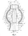
- the invention is particularly advantageous in vertical cylindrical cabins, but can also be used advantageously for coating booths whose interior in the horizontal cross section is square or rectangular or oval or the like.
- “Vertical Cylinder” means that the coating space of the cabin is in the form of a vertical cylinder.
- This cylinder preferably has a circular horizontal cross-section inside, but may also have the shape of a different arcuate cross-section or a polygon cross-section. Square cross-sections, however, are less clean than arcuate or round and can also create adverse air currents.
- the powder spray coating booth according to the invention shown in the drawings comprises two diametrically opposed object wall passages 2 and 4 for the transport of objects 6 to be coated through the powder spray coating booth and a cabin floor 8.
- the width of the object passages 2 and 4 limits the maximum width of the object transport path 16, ie the maximum width of the coatable objects 6.
- a suction channel assembly 10 is disposed at the lower end of the cabin interior 12 for exhausting air and excess powder from the cabin interior 12.
- the suction channel assembly 10 is formed for an uneven distribution of the exhaust air volume flow in such a way that viewed along the Object Transportweges 16 at least the majority or the totality of the cabin exhaust air through two kabinenend turnede suction passages 22 and 24, close to the object wall passages 2 and. 4 are provided in the cabin floor 8 or in the cabin wall adjacent to the cabin floor 8, flows out of the cabin interior.
- the exhaust air volume flow 18 contains excess powder.
- the excess powder is powder rebounding from the objects 6 to be coated and powder possibly sprayed past the objects by a spraying device 26.
- the width, height and position of the object transport path is defined by the object wall passages 2 and 4 through which it extends.
- At least one spray device slot 32 is formed, through which one or more spray devices 26 can be directed into the cabin interior 12, which are supported by a lifting device 34 located outside of the powder spray coating booth or other carrier device and are movable in the spray device slot 32 relative to the cabin wall 28.
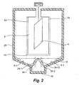
- the cabin floor 8 consists of a seen in object conveying direction 30 left side floor area 8-1 and a right side floor area 8-2, a connecting them in cabin transverse direction suction channel 36, which is parallel to the object conveying direction 30 between the two Suction passages 22 and 24 extend and connect them, and preferably a hood or channel cover 38, which covers the suction channel 36 except in the region of the suction passages 22 and 24 and with the exception of two extending in the channel longitudinal direction suction slots 40 and 42.
- the channel cover 38 forms part of the cabin floor. It preferably has the shape of a saddle roof with a roof ridge line 44 extending in the object conveying direction.
- the channel cover 38, including its roof ridge line 44 may be airtight.
- the width of the suction channel 36 is smaller than the width of the schematically indicated at 16 object transport path and thus smaller than the width of the two object wall passages 2 and 4.
- the two lateral floor areas 8-1 and 8-2 are arranged transversely to the object transport path 16 of the cabin wall halves 28-1 and 28-2 to the suction channel formed between them wedge-shaped sloping sloping, so that the cabin floor seen in vertical cross-section in Fig. 2 and 3 shown wedge shape, or shape of a wedge-like groove, and can be driven on them lying excess powder of compressed air 48 in the lower than they located suction channel 36.
- the compressed air 48 is driven by a compressed air distribution line 50 from the region of the cabin wall 28 via the lateral bottom regions 8-1 and 8-2 in the direction of the suction channel 36.
- the compressed air 48 is sucked together with other air in the cabin from the suction of a suction fan, not shown through the suction passages 22 and 24 and the suction slots 40 and 42 in the suction passage 36 and passes from the latter via a suction port 52 and then via a powder separator for depositing of powder particles, such as a cyclone and a downstream filter, via the suction fan, not shown, into the open.
- a suction fan not shown
- the compressed-air distribution line 50 consists of a line section 50-1 or 50 each extending directly on the lateral floor area 8-1 or 8-2 or close to it along the cabin inner circumferential surface of the left-hand wall half 28-1 or the right-hand wall half 28-2 -2, which extends from one to the other object wall passage 2 and 4, respectively.
- the conduit sections 50-1 and 50-2 may be a few millimeters wide from the cabin wall, so that no powder particles can accumulate therebetween, and powder particles can be manually blown off through the clearance area with compressed air.
- the channel cover 38 preferably consists of two cover parts 38-1 and 38-2, each forming a "roof half" of the gable roof channel cover 38 and abut the roof ridge line 44 to each other.
- the two cover parts 38-1 and 38-2 are each about a rotational axis 38-11 and 38-12 manually and / or motor between the illustrated, closed in the roof ridge line 44 operating position for the powder spray coating operation and a remote from the roof ridge line 44 cleaning position rotatable for cleaning purposes, the latter in Fig. 2 is shown schematically by dashed lines.
- the suction channel 36 is open at the top so that a person with a compressed air lance can direct compressed air not only to the cabin wall 28 and the cabin floor 8 but also to both sides of the cover parts 38-1 and 38-2 to blow off powder particles therefrom, so that they are sucked by the suction of the suction port 52 to clean the cabin interior.
- the flow passage cross section of the two suction slots 40 and 42 together is substantially smaller than the flow passage cross section of the two suction passages 22 and 24 together, preferably also smaller than that Flow passage section of each of the two suction passages 22 and 24th
- the transverse center of the exhaust duct 36 is aligned with the width center of the object wall passages 2 and 4.
- the roof ridge line 44 is also preferably aligned with the width center of these object wall passages 2 and 4.
- the center area of the cabin in which the objects 6 are coated is preferably completely free of suction openings.
- the two lateral floor areas 8-1 and 8-2 next to the suction channel 36 are preferably also completely free of suction openings.
- suction slots 40 and 42 instead of two suction slots 40 and 42, only a single suction slot can be provided. This can be at the in Fig. 1 shown point or in the middle of the suction channel 36 extend in the longitudinal direction.
- the channel cover 38 may consist of fixed elements instead of hinged cover parts.
- the suction slots 40 and 42 can be omitted without substitution, so that the entire cabin floor 8 is hermetically sealed, with the exception of the two suction passages 22 and 24.
- the two side bottom portions 8-1 and 8-2 can instead of funnel-shaped or wedge-shaped inward, roof-like be arranged sloping outside. In this case, it is expedient, Pulverabsaugö réelleen in Cabin floor 8 to provide along the cabin wall 28 or to form in this cabin wall. On the ridge line of such a pitched roof-like cabin floor 8 it is possible to provide compressed air outlet openings through which compressed air can drive powder lying on the cabin floor to the suction openings.
- the object exit wall passage 4 is formed as a channel, the channel side walls 54 and 56 projecting from the cabin exterior and has a projecting away from the cabin outside channel bottom 58, preferably also has a channel roof. These prevent air from the outside of the cabin tangential to the cabin inner circumferential surface 60 in the cabin interior 12 can flow through the respective object wall passage 2 and 4, respectively.
- the channel side walls 54 and 56 may be formed by two substantially parallel to each other open door wings 54 and 56, which are each pivotally mounted about a vertical axis 62 and 64 on the cabin wall 28.
- the two door leaves 54 and 56 can be pivoted into a position closing the object wall passage 4 for cleaning the powder spray coating booth.
- a person can pass through the other, open object wall passage 2 with compressed air a compressed air lance blow out the cabin interior 12.
- the coating powder blown off from the surfaces is simultaneously sucked through the suction channel 36.
- the object-inlet-side wall passage 2 may be provided with a manual coating space 66 which adjoins the object wall passage 2 on the outside of the cabin and to which the objects 6 to be coated with manual Spray guns 68 are coatable.
- This object wall passage 2 can also be opened by two door wings 74 and 76 for the spray coating operation and closed for the cleaning operation.
- the one door leaf 74 preferably serves as the rear wall of the manual coating station 66, which may additionally be extended by a stationary rear wall 78.
- the space side opposite the back wall 74, 78 is open to the manual spray gun 68.
- the back wall 74, 78 may also be adjoined by an open manual coating area to coat the objects 6 from the other side.
- a floor 80 of the manual coating space adjoins the outside of the cabin between the two doors 74 and 76.
- these two door leaves 74 and 76 of the object-inlet-side wall passage 2 can also be set parallel to each other in the open position to produce the lock effect, as described with respect to the one object wall passage 4, to a tangential inflow to prevent air in the cabin interior 12 and thus counteract eddy current formation in the cabin interior.
- the lock channel of the object-exit-side wall passage 4 depending on the position of the door wings 54 and 56 are optionally formed as a manual coating or as a channel (lock), which suppress or prevent tangential inflow of air through the object wall passage.
Landscapes
- Details Or Accessories Of Spraying Plant Or Apparatus (AREA)
- Electrostatic Spraying Apparatus (AREA)
- Nozzles (AREA)
- Fertilizers (AREA)
- Application Of Or Painting With Fluid Materials (AREA)
Claims (13)
- Cabine de poudrage, contenant deux passages de parois pour des objets (2, 4), disposés l'un en face de l'autre, pour le transport à travers la cabine de poudrage d'objets (6) à poudrer, le long d'une voie de transport d'objets (16) ; un fond de cabine (8) qui présente une région de fond latérale gauche (8-1), une région de fond latérale droite (8-2) et un canal d'aspiration (36) les reliant l'une à l'autre ; le canal d'aspiration (36) faisant partie d'un agencement de canal d'aspiration (22, 24, 36, 40, 42, 52) qui est disposé à l'extrémité inférieure de l'espace interne de la cabine (12) pour l'aspiration de l'air et de la poudre en excès hors de l'espace interne de la cabine ;
caractérisée en ce que
le canal d'aspiration (26) s'étend le long de la voie de transport d'objets (16) et relie l'une à l'autre les deux régions de fond (8-1, 8-2) dans la direction transversale de la cabine ; en ce qu'un capot ou un recouvrement de canal (38) s'étend au-dessus du canal d'aspiration (36), avec une exception dans la région de deux passages d'aspiration (22, 24) du côté de l'extrémité de la cabine, dont un est disposé près de l'un des deux passages d'objets (2, 4) et l'autre est disposé près de l'autre des deux passages d'objets (2, 4) ; l'agencement de canal d'aspiration (22, 24, 36, 40, 42, 52) étant réalisé à l'extrémité inférieure de l'espace interne de la cabine (12) pour une répartition irrégulière du débit d'air évacué (18) de telle sorte que, considéré le long de la voie de transport d'objets (16), au moins la majeure partie du débit d'air évacué (18) soit évacuée hors de l'espace interne de la cabine par les passages d'aspiration (22, 24) du côté de l'extrémité de la cabine dans le fond de la cabine (22, 24). - Cabine de poudrage selon la revendication 1,
caractérisée en ce que
les passages d'aspiration (22, 24) du côté de l'extrémité de la cabine sont connectés fluidiquement à un raccord d'aspiration (52) commun pour les deux. - Cabine de poudrage selon l'une quelconque des revendications précédentes,
caractérisée en ce
qu'une fente d'aspiration (40, 42) s'étendant dans la direction longitudinale du canal est formée entre le capot ou le recouvrement de canal (38) et au moins une, de préférence chacune, des deux régions de fond adjacentes (8-1, 8-2). - Cabine de poudrage selon l'une quelconque des revendications précédentes,
caractérisée en ce que
les deux régions de fond latérales (8-1, 8-2) adjacentes au canal d'aspiration (36) sont exemptes d'ouvertures d'aspiration de part et d'autre de la voie de transport d'objets (16). - Cabine de poudrage selon l'une quelconque des revendications précédentes,
caractérisée en ce que
les deux régions de fond latérales (8-1, 8-2) sont disposées transversalement à la voie de transport d'objets (16) de manière à descendre obliquement en forme de coin depuis la paroi de la cabine (28) jusqu'au canal d'aspiration (36), et en ce qu'au fond de la forme en coin, qui s'étend le long de la voie de transport d'objets, au moins une fente d'aspiration (40 ,42), qui s'étend le long de la voie de transport d'objets, est formée entre le capot ou le recouvrement de canal (38) et la région de fond latérale (8-1, 8-2) adjacente. - Cabine de poudrage selon la revendication 5,
caractérisée en ce que
l'au moins une fente d'aspiration (40, 42), qui débouche dans le canal d'aspiration (36) disposé sous elle, est plus étroite que le canal d'aspiration (36). - Cabine de poudrage selon l'une quelconque des revendications 3 à 6,
caractérisée en ce que
l'au moins une fente d'aspiration (40, 42) débouche au niveau de ses extrémités longitudinales dans les passages d'aspiration (22, 24) du côté de l'extrémité de la cabine. - Cabine de poudrage selon l'une quelconque des revendications précédentes,
caractérisée en ce que
le recouvrement de canal ou le capot (38) est réalisé sous la forme d'au moins une partie de recouvrement en forme de volet (38-1, 38-2), qui s'étend sous la voie de transport d'objets, le long de celle-ci, qui est disposée de manière à pouvoir tourner autour d'un axe de rotation (38-11, 38-12) s'étendant le long de la voie de transport, et qui peut tourner autour de cet axe de rotation en restant au-dessus du canal d'aspiration (36), entre une position de fonctionnement de revêtement recouvrant le canal d'aspiration, pour le fonctionnement de poudrage, et une position de nettoyage ne recouvrant pas le canal d'aspiration, pour des opérations de nettoyage. - Cabine de poudrage selon la revendication 8,
caractérisée en ce que
l'au moins une fente d'aspiration (40, 42) est limitée dans la position de fonctionnement de revêtement de la partie de recouvrement rotative en forme de volet (38-1, 38-2) par un bord longitudinal de cette partie de recouvrement (38-1, 38-2), et un bord longitudinal opposé d'une région de fond fixe (8-1, 8-2). - Cabine de poudrage selon la revendication 9,
caractérisée en ce que
deux desdites parties de recouvrement en forme de volet (38-1, 38-2) sont disposées en forme de toit et parallèlement l'une à côté de l'autre, et en ce que leurs bords longitudinaux opposés délimitent chacun l'une des fentes d'aspiration (40, 42). - Cabine de poudrage selon la revendication 10,
caractérisée en ce que
les régions de bords longitudinaux adjacentes des deux parties de recouvrement en forme de volet (38-1, 38-2) sont en appui l'une contre l'autre dans la position de fonctionnement de revêtement et forment ensemble une surface de fond fermée, mais sont espacées transversalement l'une de l'autre dans la position de nettoyage, pour souffler de l'air sous pression de nettoyage à travers la zone d'espacement formée entre elles. - Cabine de poudrage selon l'une quelconque des revendications précédentes,
caractérisée en ce
qu'il s'agit d'une cabine cylindrique verticale, dont au moins l'espace interne de cabine a la forme d'un cylindre vertical. - Cabine de poudrage selon la revendication 12,
caractérisée en ce que
au moins l'un des passages de parois pour des objets (2, 4) est réalisé sous la forme d'un canal, qui présente des parois latérales de canal (54, 56, 74, 76) saillant depuis le côté extérieur de la cabine dans la direction longitudinale de la voie de déplacement des objets et un fond de canal (58, 80) saillant depuis le côté extérieur de la cabine.
Applications Claiming Priority (2)
| Application Number | Priority Date | Filing Date | Title |
|---|---|---|---|
| DE10028553 | 2000-06-09 | ||
| DE10028553A DE10028553A1 (de) | 2000-06-09 | 2000-06-09 | Pulversprühbeschichtungskabine |
Publications (4)
| Publication Number | Publication Date |
|---|---|
| EP1162002A2 EP1162002A2 (fr) | 2001-12-12 |
| EP1162002A3 EP1162002A3 (fr) | 2003-01-15 |
| EP1162002B1 true EP1162002B1 (fr) | 2008-11-12 |
| EP1162002B8 EP1162002B8 (fr) | 2009-02-18 |
Family
ID=7645217
Family Applications (1)
| Application Number | Title | Priority Date | Filing Date |
|---|---|---|---|
| EP01110530A Expired - Lifetime EP1162002B8 (fr) | 2000-06-09 | 2001-04-28 | Cabine de poudrage |
Country Status (7)
| Country | Link |
|---|---|
| US (1) | US6589345B2 (fr) |
| EP (1) | EP1162002B8 (fr) |
| JP (1) | JP4991055B2 (fr) |
| AT (1) | ATE413928T1 (fr) |
| CA (1) | CA2349027C (fr) |
| DE (2) | DE10028553A1 (fr) |
| ES (1) | ES2316410T3 (fr) |
Cited By (1)
| Publication number | Priority date | Publication date | Assignee | Title |
|---|---|---|---|---|
| JP2002028544A (ja) * | 2000-06-09 | 2002-01-29 | Itw Gema Ag | 粉末スプレイコーティングキャビン |
Families Citing this family (23)
| Publication number | Priority date | Publication date | Assignee | Title |
|---|---|---|---|---|
| DE20107767U1 (de) * | 2001-05-08 | 2001-07-12 | Wagner International AG, Altstätten | Kabine zur Pulverbeschichtung von Werkstücken |
| DE20305947U1 (de) | 2003-04-11 | 2003-06-18 | J. Wagner AG, Altstätten | Vorrichtung zur Reinigung einer Pulverbeschichtungskabine und Pulverbeschichtungskabine mit Reinigungsvorrichtung |
| DE10350332A1 (de) * | 2003-10-29 | 2005-05-25 | Itw Gema Ag | Pulversprühbeschichtungskabine |
| ATE364453T1 (de) | 2004-11-12 | 2007-07-15 | Itw Gema Ag | Pulversprühbeschichtungskabine |
| DE102004059602A1 (de) * | 2004-12-09 | 2006-06-22 | Itw Gema Ag | Pulverbeschichtungskabine oder Unterbau dafür |
| DE102005048579A1 (de) * | 2005-10-05 | 2007-04-12 | Dürr Systems GmbH | Vorrichtung und Verfahren zum Abtrennen von Nasslack -Overspray |
| DE102005048580A1 (de) | 2005-10-05 | 2007-04-19 | Dürr Systems GmbH | Vorrichtung und Verfahren zum Abtrennen von Nasslack -Overspray |
| UA91387C2 (uk) | 2005-11-16 | 2010-07-26 | Джапан Тобакко Инк. | Система ідентифікації суміші |
| DE102007040900B4 (de) | 2007-08-24 | 2016-12-08 | Dürr Systems GmbH | Hilfsmaterialaufnahmebehälter und Verfahren zum Abtrennen von Nasslack-Overspray |
| DE102007062064B4 (de) * | 2007-12-21 | 2015-05-21 | Fraunhofer-Gesellschaft zur Förderung der angewandten Forschung e.V. | Pulverbeschichtungsvorrichtung mit platzsparender Absaugvorrichtung für Overspraypulver |
| DE102008004960A1 (de) | 2008-01-18 | 2009-07-23 | Thermotec Gmbh | Verfahren und Vorrichtung zum elektrostatischen Beschichten |
| EP2098303B2 (fr) | 2008-03-07 | 2021-12-22 | J. Wagner AG | Installation de revêtement destinée au revêtement d'une pièce à usiner |
| PL2358481T3 (pl) | 2008-12-19 | 2016-06-30 | Duerr Systems Gmbh | Instalacja lakiernicza i sposób eksploatacji instalacji lakierniczej |
| BRPI0923637A2 (pt) * | 2008-12-24 | 2019-08-27 | Honda Motor Co Ltd | aparelho para revestimento em pó e método de revestimento em pó. |
| JP5420307B2 (ja) * | 2008-12-24 | 2014-02-19 | 本田技研工業株式会社 | 粉体塗装装置 |
| JP5420301B2 (ja) * | 2008-12-24 | 2014-02-19 | 本田技研工業株式会社 | 粉体塗装方法及びその装置 |
| WO2013119487A1 (fr) * | 2012-02-06 | 2013-08-15 | Nordson Corporation | Appareil de collecte d'excédent de pulvérisation pour cabine de pulvérisation de poudre |
| CN103801488B (zh) * | 2014-02-17 | 2017-02-01 | 中山市君禾机电设备有限公司 | 一种应用于粉末喷涂线的立式圆形喷房 |
| CN112642626B (zh) * | 2020-12-15 | 2022-03-04 | 电子科技大学中山学院 | 一种板式家具自动化喷漆装置 |
| CN113649208A (zh) * | 2021-09-01 | 2021-11-16 | 浙江国达智能机电装备科技有限公司 | 一种用于粉末的扬粉抽吸系统 |
| CN115301460A (zh) * | 2022-09-20 | 2022-11-08 | 中山彦本涂装科技有限公司 | 一种粉末喷涂生产线 |
| CN115634797B (zh) * | 2022-11-02 | 2023-07-07 | 中国电器科学研究院股份有限公司 | 一种人机混合型喷漆系统及其使用方法 |
| CN118080213B (zh) * | 2024-04-26 | 2024-08-06 | 四川公路工程咨询监理有限公司 | 一种隧道定向反光涂料的喷涂方法及相关装置 |
Family Cites Families (23)
| Publication number | Priority date | Publication date | Assignee | Title |
|---|---|---|---|---|
| DE7014433U (fr) | 1970-04-16 | 1970-09-17 | Hoffmann H Trocken Und Lackierofen Fabrik Apparatebau | |
| ES181314Y (es) * | 1971-10-29 | 1974-03-01 | Mamellini | Aparato perfeccionado para el rociado por pulverizacion de polvos protectores. |
| US3814002A (en) * | 1973-04-26 | 1974-06-04 | Nordson Corp | Powder spray booth |
| CH611184A5 (fr) * | 1975-09-29 | 1979-05-31 | Gema Ag | |
| US4338364A (en) * | 1980-01-14 | 1982-07-06 | Nordson Corporation | Continuous coater |
| CA1162732A (fr) * | 1980-01-14 | 1984-02-28 | James L. Kennon | Dispositif d'enduction en continu |
| FR2477431A1 (fr) * | 1980-03-05 | 1981-09-11 | Cepem | Procede et dispositif de reionisation de poudre isolante dans une installation de poudrage electrostatique d'objets |
| US5074238A (en) * | 1990-05-23 | 1991-12-24 | Binks Manufacturing Company | Production line paint spray booth with dual slots |
| JP3027826B2 (ja) * | 1990-06-05 | 2000-04-04 | 日本パーカライジング株式会社 | 粉体塗装ブームシステム |
| DE4300832A1 (de) * | 1993-01-14 | 1994-07-21 | Gema Volstatic Ag St Gallen | Pulver-Sprühbeschichtungsvorrichtung |
| DE4300837A1 (de) * | 1993-01-14 | 1994-07-21 | Gema Volstatic Ag St Gallen | Pulver-Sprühbeschichtungsanlage |
| DE19500873A1 (de) * | 1995-01-13 | 1996-07-18 | Gema Volstatic Ag | Sprühbeschichtungsvorrichtung |
| DE19549533C2 (de) * | 1995-01-13 | 1999-09-09 | Itw Gema Ag | Sprühbeschichtungsvorrichtung |
| DE19517229A1 (de) * | 1995-05-11 | 1996-11-14 | Gema Volstatic Ag | Verfahren und Vorrichtung zur Pulver-Sprühbeschichtung |
| DE19616220A1 (de) * | 1996-04-23 | 1997-10-30 | Erich Kraemer | Pulverbeschichtungskabine |
| DE19644360C2 (de) * | 1996-10-25 | 2002-01-03 | Pbs Pulverbeschichtungs Und Sp | Farbsprühkabine mit Düsen zur Erzeugung horizontal gerichteter Querluftströme |
| DE19645261A1 (de) * | 1996-11-02 | 1998-05-07 | Gema Volstatic Ag | Vorrichtung zum Sprühbeschichten von Objekten |
| DE19645262A1 (de) * | 1996-11-02 | 1998-05-07 | Gema Volstatic Ag | Pulver-Sprühbeschichtungskabine |
| GB9718944D0 (en) * | 1997-09-05 | 1997-11-12 | Nordson Corp | Improvements relating to powder spray coating |
| DE19827877A1 (de) | 1998-06-23 | 2000-01-20 | Michael Bongards | Prozeßoptimierung einer nach dem Belebungsverfahren arbeitenden Kläranlage |
| JP2000005666A (ja) * | 1998-06-24 | 2000-01-11 | Matsushita Electric Works Ltd | スプレー塗装装置と塗装方法 |
| DE19837877A1 (de) * | 1998-08-20 | 2000-02-24 | Erich Kraemer | Pulverbeschichtungsanlage |
| DE10028553A1 (de) * | 2000-06-09 | 2001-12-13 | Itw Gema Ag | Pulversprühbeschichtungskabine |
-
2000
- 2000-06-09 DE DE10028553A patent/DE10028553A1/de not_active Ceased
-
2001
- 2001-04-28 AT AT01110530T patent/ATE413928T1/de active
- 2001-04-28 ES ES01110530T patent/ES2316410T3/es not_active Expired - Lifetime
- 2001-04-28 DE DE50114480T patent/DE50114480D1/de not_active Expired - Lifetime
- 2001-04-28 EP EP01110530A patent/EP1162002B8/fr not_active Expired - Lifetime
- 2001-05-29 CA CA002349027A patent/CA2349027C/fr not_active Expired - Fee Related
- 2001-06-04 US US09/871,675 patent/US6589345B2/en not_active Expired - Lifetime
- 2001-06-08 JP JP2001174406A patent/JP4991055B2/ja not_active Expired - Fee Related
Cited By (1)
| Publication number | Priority date | Publication date | Assignee | Title |
|---|---|---|---|---|
| JP2002028544A (ja) * | 2000-06-09 | 2002-01-29 | Itw Gema Ag | 粉末スプレイコーティングキャビン |
Also Published As
| Publication number | Publication date |
|---|---|
| EP1162002A2 (fr) | 2001-12-12 |
| ATE413928T1 (de) | 2008-11-15 |
| DE50114480D1 (de) | 2008-12-24 |
| US6589345B2 (en) | 2003-07-08 |
| EP1162002B8 (fr) | 2009-02-18 |
| CA2349027C (fr) | 2006-03-14 |
| JP2002028544A (ja) | 2002-01-29 |
| EP1162002A3 (fr) | 2003-01-15 |
| CA2349027A1 (fr) | 2001-12-09 |
| JP4991055B2 (ja) | 2012-08-01 |
| ES2316410T3 (es) | 2009-04-16 |
| DE10028553A1 (de) | 2001-12-13 |
| US20020020347A1 (en) | 2002-02-21 |
Similar Documents
| Publication | Publication Date | Title |
|---|---|---|
| EP1162002B1 (fr) | Cabine de poudrage | |
| EP2040854B1 (fr) | Installation de mise en peinture et procédé de fonctionnement associé | |
| EP0629154B1 (fr) | Dispositif de saupoudrage | |
| DE1752212A1 (de) | Anlage zum Beschichten von Gegenstaenden | |
| CH638698A5 (de) | Beschichtungsvorrichtung fuer das elektrostatische auftragen von pulverfoermigen stoffen. | |
| EP3335802B1 (fr) | Cabine de revêtement par pulvérisation, installation de revêtement par pulvérisation et procédé de fonctionnement d'une cabine de revêtement par pulvérisation | |
| EP2058055A1 (fr) | Cabine destinée à recouvrir une pièce à usiner avec de la poudre | |
| EP0839582B1 (fr) | Cabine de pulvérisation de poudre pour revêtement automatique et manuel | |
| DE20320735U1 (de) | Pulverbeschichtungspritzkabine mit einem Pulverabsaugsystem | |
| DE4447818C2 (de) | Verfahren zur Pulverbeschichtung und Lackieranlage zur Durchführung des Verfahrens | |
| DE19645261A1 (de) | Vorrichtung zum Sprühbeschichten von Objekten | |
| EP4037840A1 (fr) | Système de traitement et procédé de traitement | |
| EP0892683A1 (fr) | Cabine de pulverisation | |
| EP1819447B1 (fr) | Cabine d'application de revetement pulverulent ou infrastructure pour cette derniere | |
| EP1125639B1 (fr) | Cabine de poudrage de pièces | |
| DE102010032144A1 (de) | Behandlungseinheit und Anlage zur Oberflächenbehandlung von Gegenständen | |
| DE3419028A1 (de) | Verfahren zum reinigen von koerpern mit luftstrahlen und vorrichtung zur durchfuehrung des verfahrens | |
| EP1466670B1 (fr) | Dispositif de nettoyage de cabine de revêtement par poudrage et cabine de revêtement par poudrage munie d'un dispositif de nettoyage | |
| DE19524327A1 (de) | Pulverbeschichtungskabine | |
| DE10350332A1 (de) | Pulversprühbeschichtungskabine | |
| DE29521972U1 (de) | Pulverbeschichtungskabine | |
| DE69417151T2 (de) | Anordnung zum Fördern einer Luftströmung mit einer flachen Gestalt | |
| DE3318043A1 (de) | Einrichtung zum beschichten von gegenstaenden | |
| EP1656998B1 (fr) | Cabine de pulvérisation de poudre | |
| DE19722773C1 (de) | Pulverbeschichtungskabine mit drehbarem Kabinenwandträger |
Legal Events
| Date | Code | Title | Description |
|---|---|---|---|
| PUAI | Public reference made under article 153(3) epc to a published international application that has entered the european phase |
Free format text: ORIGINAL CODE: 0009012 |
|
| AK | Designated contracting states |
Kind code of ref document: A2 Designated state(s): AT BE CH CY DE DK ES FI FR GB GR IE IT LI LU MC NL PT SE TR |
|
| AX | Request for extension of the european patent |
Free format text: AL;LT;LV;MK;RO;SI |
|
| PUAL | Search report despatched |
Free format text: ORIGINAL CODE: 0009013 |
|
| AK | Designated contracting states |
Kind code of ref document: A3 Designated state(s): AT BE CH CY DE DK ES FI FR GB GR IE IT LI LU MC NL PT SE TR |
|
| AX | Request for extension of the european patent |
Free format text: AL;LT;LV;MK;RO;SI |
|
| 17P | Request for examination filed |
Effective date: 20030214 |
|
| AKX | Designation fees paid |
Designated state(s): AT CH DE ES FR IT LI |
|
| 17Q | First examination report despatched |
Effective date: 20070322 |
|
| GRAP | Despatch of communication of intention to grant a patent |
Free format text: ORIGINAL CODE: EPIDOSNIGR1 |
|
| GRAS | Grant fee paid |
Free format text: ORIGINAL CODE: EPIDOSNIGR3 |
|
| GRAA | (expected) grant |
Free format text: ORIGINAL CODE: 0009210 |
|
| AK | Designated contracting states |
Kind code of ref document: B1 Designated state(s): AT CH DE ES FR IT LI |
|
| REG | Reference to a national code |
Ref country code: CH Ref legal event code: EP |
|
| RAP2 | Party data changed (patent owner data changed or rights of a patent transferred) |
Owner name: ITW GEMA GMBH |
|
| REF | Corresponds to: |
Ref document number: 50114480 Country of ref document: DE Date of ref document: 20081224 Kind code of ref document: P |
|
| REG | Reference to a national code |
Ref country code: ES Ref legal event code: FG2A Ref document number: 2316410 Country of ref document: ES Kind code of ref document: T3 |
|
| PLBE | No opposition filed within time limit |
Free format text: ORIGINAL CODE: 0009261 |
|
| STAA | Information on the status of an ep patent application or granted ep patent |
Free format text: STATUS: NO OPPOSITION FILED WITHIN TIME LIMIT |
|
| 26N | No opposition filed |
Effective date: 20090813 |
|
| REG | Reference to a national code |
Ref country code: FR Ref legal event code: CD Owner name: ITW GEMA GMBH Effective date: 20120425 |
|
| REG | Reference to a national code |
Ref country code: DE Ref legal event code: R081 Ref document number: 50114480 Country of ref document: DE Owner name: GEMA SWITZERLAND GMBH, CH Free format text: FORMER OWNER: ITW GEMA GMBH, ST. GALLEN, CH Effective date: 20121213 |
|
| REG | Reference to a national code |
Ref country code: CH Ref legal event code: PFA Owner name: GEMA SWITZERLAND GMBH, CH Free format text: FORMER OWNER: ITW GEMA GMBH, CH |
|
| REG | Reference to a national code |
Ref country code: ES Ref legal event code: PC2A Owner name: GEMA SWITZERLAND GMBH Effective date: 20131223 |
|
| REG | Reference to a national code |
Ref country code: FR Ref legal event code: CD Owner name: GEMA SWITZERLAND GMBH Effective date: 20140106 |
|
| REG | Reference to a national code |
Ref country code: AT Ref legal event code: HC Ref document number: 413928 Country of ref document: AT Kind code of ref document: T Owner name: GEMA SWITZERLAND GMBH, CH Effective date: 20131219 |
|
| PGFP | Annual fee paid to national office [announced via postgrant information from national office to epo] |
Ref country code: ES Payment date: 20140428 Year of fee payment: 14 Ref country code: AT Payment date: 20140402 Year of fee payment: 14 |
|
| REG | Reference to a national code |
Ref country code: AT Ref legal event code: MM01 Ref document number: 413928 Country of ref document: AT Kind code of ref document: T Effective date: 20150428 |
|
| PG25 | Lapsed in a contracting state [announced via postgrant information from national office to epo] |
Ref country code: AT Free format text: LAPSE BECAUSE OF NON-PAYMENT OF DUE FEES Effective date: 20150428 |
|
| REG | Reference to a national code |
Ref country code: FR Ref legal event code: PLFP Year of fee payment: 16 |
|
| REG | Reference to a national code |
Ref country code: ES Ref legal event code: FD2A Effective date: 20160527 |
|
| PG25 | Lapsed in a contracting state [announced via postgrant information from national office to epo] |
Ref country code: ES Free format text: LAPSE BECAUSE OF NON-PAYMENT OF DUE FEES Effective date: 20150429 |
|
| REG | Reference to a national code |
Ref country code: FR Ref legal event code: PLFP Year of fee payment: 17 |
|
| REG | Reference to a national code |
Ref country code: DE Ref legal event code: R079 Ref document number: 50114480 Country of ref document: DE Free format text: PREVIOUS MAIN CLASS: B05B0015120000 Ipc: B05B0016000000 |
|
| REG | Reference to a national code |
Ref country code: FR Ref legal event code: PLFP Year of fee payment: 18 |
|
| PGFP | Annual fee paid to national office [announced via postgrant information from national office to epo] |
Ref country code: FR Payment date: 20200427 Year of fee payment: 20 Ref country code: DE Payment date: 20200429 Year of fee payment: 20 Ref country code: CH Payment date: 20200504 Year of fee payment: 20 |
|
| PGFP | Annual fee paid to national office [announced via postgrant information from national office to epo] |
Ref country code: IT Payment date: 20200423 Year of fee payment: 20 |
|
| REG | Reference to a national code |
Ref country code: DE Ref legal event code: R071 Ref document number: 50114480 Country of ref document: DE |
|
| REG | Reference to a national code |
Ref country code: CH Ref legal event code: PL |