EP2098303B2 - Installation de revêtement destinée au revêtement d'une pièce à usiner - Google Patents
Installation de revêtement destinée au revêtement d'une pièce à usiner Download PDFInfo
- Publication number
- EP2098303B2 EP2098303B2 EP08405068.1A EP08405068A EP2098303B2 EP 2098303 B2 EP2098303 B2 EP 2098303B2 EP 08405068 A EP08405068 A EP 08405068A EP 2098303 B2 EP2098303 B2 EP 2098303B2
- Authority
- EP
- European Patent Office
- Prior art keywords
- coating
- manual
- stand
- extraction unit
- suction
- Prior art date
- Legal status (The legal status is an assumption and is not a legal conclusion. Google has not performed a legal analysis and makes no representation as to the accuracy of the status listed.)
- Active
Links
- 238000000576 coating method Methods 0.000 title claims description 116
- 239000011248 coating agent Substances 0.000 title claims description 115
- 238000000605 extraction Methods 0.000 claims description 25
- 238000000034 method Methods 0.000 claims description 6
- 239000000843 powder Substances 0.000 description 24
- 229940098458 powder spray Drugs 0.000 description 10
- 239000007921 spray Substances 0.000 description 5
- 108010066057 cabin-1 Proteins 0.000 description 4
- 239000003086 colorant Substances 0.000 description 3
- 238000010438 heat treatment Methods 0.000 description 2
- 238000005507 spraying Methods 0.000 description 2
- 235000019646 color tone Nutrition 0.000 description 1
- 230000001419 dependent effect Effects 0.000 description 1
- 238000011161 development Methods 0.000 description 1
- 230000018109 developmental process Effects 0.000 description 1
- 238000009434 installation Methods 0.000 description 1
- 239000000463 material Substances 0.000 description 1
- 238000012986 modification Methods 0.000 description 1
- 230000004048 modification Effects 0.000 description 1
- 238000011084 recovery Methods 0.000 description 1
Images

Classifications
-
- B—PERFORMING OPERATIONS; TRANSPORTING
- B05—SPRAYING OR ATOMISING IN GENERAL; APPLYING FLUENT MATERIALS TO SURFACES, IN GENERAL
- B05B—SPRAYING APPARATUS; ATOMISING APPARATUS; NOZZLES
- B05B16/00—Spray booths
- B05B16/20—Arrangements for spraying in combination with other operations, e.g. drying; Arrangements enabling a combination of spraying operations
- B05B16/25—Arrangements for spraying in combination with other operations, e.g. drying; Arrangements enabling a combination of spraying operations for both automatic and manual spraying
-
- B—PERFORMING OPERATIONS; TRANSPORTING
- B05—SPRAYING OR ATOMISING IN GENERAL; APPLYING FLUENT MATERIALS TO SURFACES, IN GENERAL
- B05B—SPRAYING APPARATUS; ATOMISING APPARATUS; NOZZLES
- B05B14/00—Arrangements for collecting, re-using or eliminating excess spraying material
- B05B14/40—Arrangements for collecting, re-using or eliminating excess spraying material for use in spray booths
- B05B14/45—Arrangements for collecting, re-using or eliminating excess spraying material for use in spray booths using cyclone separators
-
- B—PERFORMING OPERATIONS; TRANSPORTING
- B05—SPRAYING OR ATOMISING IN GENERAL; APPLYING FLUENT MATERIALS TO SURFACES, IN GENERAL
- B05B—SPRAYING APPARATUS; ATOMISING APPARATUS; NOZZLES
- B05B14/00—Arrangements for collecting, re-using or eliminating excess spraying material
- B05B14/40—Arrangements for collecting, re-using or eliminating excess spraying material for use in spray booths
- B05B14/48—Arrangements for collecting, re-using or eliminating excess spraying material for use in spray booths specially adapted for particulate material
-
- B—PERFORMING OPERATIONS; TRANSPORTING
- B05—SPRAYING OR ATOMISING IN GENERAL; APPLYING FLUENT MATERIALS TO SURFACES, IN GENERAL
- B05B—SPRAYING APPARATUS; ATOMISING APPARATUS; NOZZLES
- B05B16/00—Spray booths
- B05B16/90—Spray booths comprising conveying means for moving objects or other work to be sprayed in and out of the booth, e.g. through the booth
-
- B—PERFORMING OPERATIONS; TRANSPORTING
- B05—SPRAYING OR ATOMISING IN GENERAL; APPLYING FLUENT MATERIALS TO SURFACES, IN GENERAL
- B05B—SPRAYING APPARATUS; ATOMISING APPARATUS; NOZZLES
- B05B14/00—Arrangements for collecting, re-using or eliminating excess spraying material
- B05B14/40—Arrangements for collecting, re-using or eliminating excess spraying material for use in spray booths
- B05B14/43—Arrangements for collecting, re-using or eliminating excess spraying material for use in spray booths by filtering the air charged with excess material
Definitions
- the invention relates to a coating system for coating a workpiece and a method for operating the coating system.
- the coating system is suitable, for example, for coating workpieces with coating powder, which is hereinafter referred to as powder for short.
- a coating system usually has a booth with side walls through which one or more powder spray guns protrude into the interior of the booth.
- the workpiece to be coated is transported hanging on a conveyor track through the cabin and sprayed with powder with the powder spray guns.
- the workpiece is then transported into a heating chamber.
- the powder layer is heated in the heating chamber to such an extent that it liquefies and forms a closed layer on the workpiece.
- a booth for powder coating workpieces is known.
- a manual coating station is arranged in front of and behind the booth so that the workpiece can be coated manually. If small batches are to be coated with other materials or colors, the booth and the powder recovery device must first be cleaned. To clean the booth, a sliding door located between the manual coating station and the booth is first closed. The powder in the booth is then removed manually and the door is then opened again. This process is complex, time-consuming and is not always practicable. This combination of booth and manual coater station is therefore not suitable for working with different colors at the same time.
- a system for coating large workpieces, such as vehicles, with powder is known.
- a uniform coating of the entire vehicle body should be guaranteed and a large part of the excess powder should be collected and recovered.
- the system includes an automatic spray area and a manual coating area. All of the excess powder, i.e. both the excess powder that comes from the automatic spraying area and the excess powder that is sucked off from the manual coating area, is fed into a cyclone. With this system, it is not possible to manually coat a workpiece in the manual coating area with a different color than the color that is also used in the automatic spraying area.
- One object of the invention is to specify a coating system for coating a workpiece, in which several different color tones can be used without first having to clean the booth.
- the coating system according to the invention for coating a workpiece comprises a booth with a booth suction and a manual coating stand with a manual coating stand suction, the manual coating stand being connected to the booth.
- a post-filter is provided, which is connected to the booth suction and the manual coater suction.
- a switchover means is provided in order to be able to switch between the manual coater stand suction and the booth suction.
- the manual coating stand has a vertical suction opening which is connected to the manual coating stand suction.
- the manual coating stand can have a horizontal suction opening in the floor area, which is connected to the manual coating stand suction.
- a door can be provided between the manual coating station and the booth.
- a cyclone is provided which is connected to the post-filter. With the cyclone, the extracted excess powder can be collected and reused.
- the cyclone is connected between the booth suction and the post-filter.
- the manual coating station has a wall into which the suction opening is integrated.
- the manual coating stand has a further suction, the further suction and the manual coating stand suction being arranged on opposite sides of the manual coating stand. This allows further improve the suction.
- the further suction has a suction line which is arranged below the manual coating station. This means that the additional extraction system can be installed in a space-saving manner.
- the manual coating station has a roof.
- the manual coating stand suction is activated and the booth suction is deactivated if the workpiece is to be coated only from the manual coating stand.
- FIG. 1 an embodiment of the coating system with a booth 1, a first manual coating station 2 and a second manual coating station 3 is shown in a plan view in section.
- the booth 1 arranged between the two manual coating stands 2 and 3 has a first side wall 1.1 and a second side wall 1.2.
- a conveyor track 4 is located above the coating system, on which the workpiece 5 is transported hanging in the direction of the arrow 4.1.
- an automatic coating machine 6 with a linear guide 6.1 for powder spray guns 6.2 and 6.3. With the linear guide 6.1, the powder spray guns 6.2 and 6.3 can be moved vertically up and down.
- the side wall 1.1 there are vertical, slot-shaped openings through which the powder spray guns 6.2 and 6.3 protrude into the interior 1.7 of the booth 1.
- a further automatic coating machine 9 with a further linear guide for further powder spray guns 9.2 and 9.3.
- the side wall 1.2 there are vertical, slot-shaped openings through which the powder spray guns 9.2 and 9.3 protrude into the interior 1.7 of the cabin 1.
- the workpiece 5 is automatically coated with the powder spray guns 6.2 and 6.3 of the automatic coating machine 6 and the powder spray guns 9.2 and 9.3 of the automatic coating machine 9.
- the movement pattern generated by the automatic coating machines G and 9 is matched to the workpiece 5 in order to be able to optimally coat the workpiece 5.
- the automatic coating machine 6 is supplied with coating powder from a powder center 0 via a powder hose 7.
- two powder storage containers 8.1 and 8.2 are located in the powder center 8.
- the automatic coating machine 9 is supplied with coating powder from a further powder center 11 via a powder hose 10.
- the side wall 1.1 of the cabin 1 has a suction opening to which a suction channel 12 and a cyclone filter 13 or cyclone for short are connected.
- the side wall 1.2 of the cabin 1 also has a suction opening to which a further suction channel 17 and a further cyclone filter 18 are connected.
- the overspray is filtered out of the sucked in cabin air according to the principle of centrifugal force.
- the air pre-filtered by the cyclone filter 13 is filtered again by means of a post-filter 15 which is connected to the cyclone filter 13 via a pipe 14.
- the secondary filter 15 is often lost. This means that the powder filtered out in the secondary filter 15 is no longer fed to the coating process, but disposed of. However, this does not necessarily have to be handled in this way.
- the air pre-filtered by the further cyclone filter 18 is filtered again by means of a further post-filter 20.
- the further secondary filter 20 is connected to the further cyclone filter 18 via a pipe 19.
- the first manual coater stand 2 is located in front of the booth 1. This can be reached by the staff via a staircase 2.1 and has a side wall 2.2 into which a suction opening is integrated. If overspray occurs during manual coating in the manual coating station 2, this is sucked into the post-filter 20 via the suction opening and a suction channel 21. This ensures that from the manual coater stand 2 no overspray reaches the interior 1.7 of the booth 1.
- the second manual coater stand 3 is located behind the booth 1. This can be reached by the staff via a staircase 3.3 and has a first side wall 3.1 and a second side wall 3.2.
- the two side walls 3.1 and 3.2 can, in contrast to what is shown in the figure, also be shaped identically or as a mirror image.
- a horizontally running suction opening is integrated into the first side wall 3.1 in the bottom area.
- a vertically running suction opening with a vertical suction channel 22 is integrated into the second side wall 3.2, which is connected to a suction channel 23 running under the floor of the manual coating stand 3.
- the suction channel 23 in turn opens into a suction channel 16 which leads to the post-filter 15.
- overspray occurs in the manual coating station 3 during manual coating, it is sucked into the post-filter 20 via the two suction openings, the suction channel 22, the suction channel 23 and the suction channel 16. This ensures that no overspray reaches the interior of the booth 1 from the manual coating station 3.
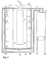
- Figure 2 shows the coating system according to the invention in a side view in section along the cutting edge AA.
- the suction openings in the booth 1 and in the manual coating stands 2 and 3 can be designed as slots or holes, for example.
- the suction openings 34 in the manual coating station 3 are designed as holes.
- the two manual coating stations 2 and 3 can each be equipped with a door 27 and 26, respectively, in order to separate the manual coating stations 2 and 3 from the interior of the booth. This can ensure that no overspray from the manual coating stands 2 and 3 gets into the interior of the booth 1.
- two servomotors 33 are activated by means of a switchover control 25 in order to operate two flaps 30 and 31 via these.
- a switchover control 25 By closing the flap 30, the booth suction is switched off and by opening the flap 31, the manual coater suction is activated.
- the switchover control 25, the servomotors 33 and the two flaps 30 and 31 are also referred to as switchover means.
- two servomotors 32 are controlled by means of a switching control 24 in order to operate two flaps 28 and 29 via these.
- the booth suction is switched off and by opening the flap 28, the manual coater suction is activated.
- the probability of overspray getting from the manual coating station 2 into the interior 1.7 of the booth 1 during manual coating can be further reduced. This is particularly advantageous when working with different colors.
- the arrows in the figure indicate the direction of flow of the air that is sucked out through the suction openings in the side walls 3.1 and 3.2.
- the two manual coating stations 2 and 3 can each be equipped with a roof 35 and the cabin with a roof 36.
- the manual coating stand 2 like the manual coating stand 3, can be equipped with a horizontal and / or a vertical suction opening.
- the coating system can also be equipped with only one manual coating station.
- the transport direction of the workpiece 5 can also point in the opposite direction.
- the coating system can advantageously be used in multi-color mode.
- On the manual coating stands 2 and 3, different, smaller batches of workpieces can be coated with color shades that differ from the main color shade in booth 1.
- both the flap 30 in the booth suction 12 and the flap 31 in the manual coater suction 16 can be partially open.
- the flaps 30 and 31 can be adjusted so that 80% of the extracted air volume is extracted via the booth extraction system 12 and the remaining 20% of the extracted air volume via the manual coater stand extraction system 16. In this way, the powder loss via the manual coating station 3 can be reduced even further.
Landscapes
- Details Or Accessories Of Spraying Plant Or Apparatus (AREA)
- Coating Apparatus (AREA)
- Application Of Or Painting With Fluid Materials (AREA)
Claims (11)
- Installation de revêtement pour le revêtement d'une pièce,- sur laquelle est prévue une cabine (1) avec une aspiration de cabine (12; 17),- sur laquelle est prévu un poste de revêtement manuel (2; 3) avec une aspiration de poste de revêtement manuel (16; 21),- sur laquelle le poste de revêtement manuel (2) vient se raccorder à la cabine (1),- sur laquelle est prévu un filtre secondaire (15; 20), lequel est relié à l'aspiration de cabine (12; 17) et l'aspiration de poste de revêtement manuel (16; 21), et- sur laquelle est prévu un cyclone (13; 18), lequel est relié entre l'aspiration de cabine (12) et le filtre secondaire (15).
- Installation de revêtement conformément à la revendication 1,
sur laquelle un moyen de commutation (24; 25) est prévu afin de pouvoir basculer entre l'aspiration de poste de revêtement manuel (16; 21) et l'aspiration de cabine (12; 17). - Installation de revêtement conformément à la revendication 1 ou 2,
sur laquelle le poste de revêtement manuel (3) présente un orifice d'aspiration (34) vertical, lequel est relié à l'aspiration de poste de revêtement manuel (16). - Installation de revêtement conformément à l'une des revendications 1 à 3,
sur laquelle le poste de revêtement manuel (3) présente un orifice d'aspiration (34) horizontal dans la zone du fond, lequel est relié à l'aspiration de poste de revêtement manuel (16). - Installation de revêtement conformément à la revendication 4,
sur laquelle une porte (26; 27) est prévue entre le poste de revêtement manuel (2; 3) et la cabine (1). - Installation de revêtement conformément à l'une des revendications 2 à 5,
sur laquelle le poste de revêtement manuel (2; 3) présente une paroi (3.1; 2.2) dans laquelle est intégré l'orifice d'aspiration (34). - Installation de revêtement conformément à l'une des revendications de brevet précédentes,
sur laquelle le poste de revêtement manuel (3) présente une aspiration (22, 23) supplémentaire, l'aspiration (22, 23) supplémentaire et l'aspiration de poste de revêtement manuel (16) étant disposées sur les côtés opposés du poste de revêtement manuel (3) . - Installation de revêtement conformément à la revendication 7,
sur laquelle l'aspiration (22, 23) supplémentaire présente un conduit d'aspiration (23) qui est disposé sous le poste de revêtement manuel (3). - Installation de revêtement conformément à l'une des revendications de brevet précédentes,
sur laquelle le poste de revêtement manuel (2; 3) présente un toit (35). - Procédé pour l'exploitation d'une installation de revêtement conformément à l'une des revendications 1 à 9,
dans lequel l'aspiration de poste de revêtement manuel (16) et l'aspiration de cabine (12) sont activées. - Procédé pour l'exploitation d'une installation de revêtement conformément à l'une des revendications 1 à 9,
dans lequel l'aspiration de poste de revêtement manuel (16) est activée et l'aspiration de cabine (12) est désactivée si le revêtement de la pièce (5) ne doit s'effectuer que depuis le poste de revêtement manuel (3).
Priority Applications (1)
| Application Number | Priority Date | Filing Date | Title |
|---|---|---|---|
| EP08405068.1A EP2098303B2 (fr) | 2008-03-07 | 2008-03-07 | Installation de revêtement destinée au revêtement d'une pièce à usiner |
Applications Claiming Priority (1)
| Application Number | Priority Date | Filing Date | Title |
|---|---|---|---|
| EP08405068.1A EP2098303B2 (fr) | 2008-03-07 | 2008-03-07 | Installation de revêtement destinée au revêtement d'une pièce à usiner |
Publications (3)
| Publication Number | Publication Date |
|---|---|
| EP2098303A1 EP2098303A1 (fr) | 2009-09-09 |
| EP2098303B1 EP2098303B1 (fr) | 2019-02-06 |
| EP2098303B2 true EP2098303B2 (fr) | 2021-12-22 |
Family
ID=39469950
Family Applications (1)
| Application Number | Title | Priority Date | Filing Date |
|---|---|---|---|
| EP08405068.1A Active EP2098303B2 (fr) | 2008-03-07 | 2008-03-07 | Installation de revêtement destinée au revêtement d'une pièce à usiner |
Country Status (1)
| Country | Link |
|---|---|
| EP (1) | EP2098303B2 (fr) |
Families Citing this family (1)
| Publication number | Priority date | Publication date | Assignee | Title |
|---|---|---|---|---|
| EP2368643A1 (fr) * | 2010-03-09 | 2011-09-28 | J. Wagner AG | Installation de revêtement par poudre destinée à recouvrir des pièces usinées avec de la poudre |
Citations (5)
| Publication number | Priority date | Publication date | Assignee | Title |
|---|---|---|---|---|
| DE19500872A1 (de) † | 1995-01-13 | 1996-07-18 | Gema Volstatic Ag | Sprühbeschichtungsvorrichtung |
| DE19549186A1 (de) † | 1995-12-30 | 1997-07-03 | Gema Volstatic Ag | Pulver-Sprühbeschichtungsvorrichtung |
| DE19645262A1 (de) † | 1996-11-02 | 1998-05-07 | Gema Volstatic Ag | Pulver-Sprühbeschichtungskabine |
| DE20107767U1 (de) † | 2001-05-08 | 2001-07-12 | Wagner International AG, Altstätten | Kabine zur Pulverbeschichtung von Werkstücken |
| DE10028553A1 (de) † | 2000-06-09 | 2001-12-13 | Itw Gema Ag | Pulversprühbeschichtungskabine |
Family Cites Families (6)
| Publication number | Priority date | Publication date | Assignee | Title |
|---|---|---|---|---|
| US3807291A (en) * | 1972-03-27 | 1974-04-30 | Du Pont | Improved painting system |
| US5078084A (en) * | 1990-04-16 | 1992-01-07 | Nordson Corporation | Powder coating system |
| DE19616220A1 (de) * | 1996-04-23 | 1997-10-30 | Erich Kraemer | Pulverbeschichtungskabine |
| JPH10314655A (ja) * | 1997-05-20 | 1998-12-02 | Honda Motor Co Ltd | 粉体塗装ブース |
| US6866717B2 (en) * | 2000-10-05 | 2005-03-15 | Nordson Corporation | Powder coating spray booth with air curtain |
| DE10162033A1 (de) * | 2001-12-17 | 2003-06-26 | Erich Bauer | Schalenversetzte Pulverbeschichtungskabine |
-
2008
- 2008-03-07 EP EP08405068.1A patent/EP2098303B2/fr active Active
Patent Citations (5)
| Publication number | Priority date | Publication date | Assignee | Title |
|---|---|---|---|---|
| DE19500872A1 (de) † | 1995-01-13 | 1996-07-18 | Gema Volstatic Ag | Sprühbeschichtungsvorrichtung |
| DE19549186A1 (de) † | 1995-12-30 | 1997-07-03 | Gema Volstatic Ag | Pulver-Sprühbeschichtungsvorrichtung |
| DE19645262A1 (de) † | 1996-11-02 | 1998-05-07 | Gema Volstatic Ag | Pulver-Sprühbeschichtungskabine |
| DE10028553A1 (de) † | 2000-06-09 | 2001-12-13 | Itw Gema Ag | Pulversprühbeschichtungskabine |
| DE20107767U1 (de) † | 2001-05-08 | 2001-07-12 | Wagner International AG, Altstätten | Kabine zur Pulverbeschichtung von Werkstücken |
Also Published As
| Publication number | Publication date |
|---|---|
| EP2098303B1 (fr) | 2019-02-06 |
| EP2098303A1 (fr) | 2009-09-09 |
Similar Documents
| Publication | Publication Date | Title |
|---|---|---|
| EP3147613B1 (fr) | Chambre de traitement comprenant un dispositif pour insuffler un fluide gazeux | |
| EP1819447B1 (fr) | Cabine d'application de revetement pulverulent ou infrastructure pour cette derniere | |
| DE10115376B4 (de) | Anlage zum Pulverlackieren von Gegenständen | |
| EP2058055A1 (fr) | Cabine destinée à recouvrir une pièce à usiner avec de la poudre | |
| WO2019063125A1 (fr) | Installation de revêtement par poudre pour le revêtement d'une pièce d'une poudre de revêtement | |
| WO2008107056A1 (fr) | Dispositif de peinture | |
| EP1342507B1 (fr) | Dispositif pour le revêtement en poudre d'objets | |
| EP3335802B1 (fr) | Cabine de revêtement par pulvérisation, installation de revêtement par pulvérisation et procédé de fonctionnement d'une cabine de revêtement par pulvérisation | |
| CH711291A1 (de) | Anordnung sowie Verfahren zum Beschichten von Werkstücken. | |
| EP3265240A1 (fr) | Dispositif de revêtement comprenant une arête de rupture ajustable | |
| EP3612475A1 (fr) | Système de transport, installation de traitement et procédé de transport | |
| EP2275209B1 (fr) | Cabine destinée à recouvrir des pièces à usiner avec de la poudre | |
| EP2098303B2 (fr) | Installation de revêtement destinée au revêtement d'une pièce à usiner | |
| EP3814710A1 (fr) | Dispositif de séparation et installation de traitement | |
| EP3703870A1 (fr) | Installation et procédé de revêtement d'objets | |
| DE19722773C1 (de) | Pulverbeschichtungskabine mit drehbarem Kabinenwandträger | |
| DE19822537A1 (de) | Reinigungsvorrichtung für Karosserien von Fahrzeugen | |
| EP2368643A1 (fr) | Installation de revêtement par poudre destinée à recouvrir des pièces usinées avec de la poudre | |
| DE102006055688A1 (de) | Pulverbeschichtungskabine | |
| WO2017157608A1 (fr) | Installation de mise en peinture et procédé pour la mise en peinture d'une pièce ainsi qu'élément de filtre correspondant | |
| DE202005019313U1 (de) | Pulverbeschichtungskabine | |
| EP4249130A1 (fr) | Cabine de revêtement pour revêtir des pièces avec un matériau de revêtement | |
| EP2272593A1 (fr) | Cabine destinée à recouvrir des pièces à usiner avec de la poudre | |
| DE102022108374A1 (de) | Beschichtungskabine zum beschichten von werkstücken mit beschichtungsmaterial | |
| WO2004007093A2 (fr) | Procede de revetement, en particulier de peinture d'objets |
Legal Events
| Date | Code | Title | Description |
|---|---|---|---|
| PUAI | Public reference made under article 153(3) epc to a published international application that has entered the european phase |
Free format text: ORIGINAL CODE: 0009012 |
|
| AK | Designated contracting states |
Kind code of ref document: A1 Designated state(s): AT BE BG CH CY CZ DE DK EE ES FI FR GB GR HR HU IE IS IT LI LT LU LV MC MT NL NO PL PT RO SE SI SK TR |
|
| AX | Request for extension of the european patent |
Extension state: AL BA MK RS |
|
| 17P | Request for examination filed |
Effective date: 20100309 |
|
| AKX | Designation fees paid |
Designated state(s): DE FR IT |
|
| 17Q | First examination report despatched |
Effective date: 20100423 |
|
| REG | Reference to a national code |
Ref country code: DE Ref legal event code: R079 Ref document number: 502008016596 Country of ref document: DE Free format text: PREVIOUS MAIN CLASS: B05B0015120000 Ipc: B05B0014480000 |
|
| RIC1 | Information provided on ipc code assigned before grant |
Ipc: B05B 14/48 20180101AFI20180619BHEP |
|
| GRAP | Despatch of communication of intention to grant a patent |
Free format text: ORIGINAL CODE: EPIDOSNIGR1 |
|
| STAA | Information on the status of an ep patent application or granted ep patent |
Free format text: STATUS: GRANT OF PATENT IS INTENDED |
|
| INTG | Intention to grant announced |
Effective date: 20180727 |
|
| GRAJ | Information related to disapproval of communication of intention to grant by the applicant or resumption of examination proceedings by the epo deleted |
Free format text: ORIGINAL CODE: EPIDOSDIGR1 |
|
| STAA | Information on the status of an ep patent application or granted ep patent |
Free format text: STATUS: EXAMINATION IS IN PROGRESS |
|
| GRAP | Despatch of communication of intention to grant a patent |
Free format text: ORIGINAL CODE: EPIDOSNIGR1 |
|
| STAA | Information on the status of an ep patent application or granted ep patent |
Free format text: STATUS: GRANT OF PATENT IS INTENDED |
|
| GRAS | Grant fee paid |
Free format text: ORIGINAL CODE: EPIDOSNIGR3 |
|
| GRAA | (expected) grant |
Free format text: ORIGINAL CODE: 0009210 |
|
| STAA | Information on the status of an ep patent application or granted ep patent |
Free format text: STATUS: THE PATENT HAS BEEN GRANTED |
|
| INTG | Intention to grant announced |
Effective date: 20181213 |
|
| AK | Designated contracting states |
Kind code of ref document: B1 Designated state(s): DE FR IT |
|
| RIC2 | Information provided on ipc code assigned after grant |
Ipc: B05B 14/48 20180101AFI20180619BHEP |
|
| REG | Reference to a national code |
Ref country code: DE Ref legal event code: R096 Ref document number: 502008016596 Country of ref document: DE |
|
| REG | Reference to a national code |
Ref country code: DE Ref legal event code: R081 Ref document number: 502008016596 Country of ref document: DE Owner name: WAGNER INTERNATIONAL AG, CH Free format text: FORMER OWNER: J. WAGNER AG, ALTSTAETTEN, CH |
|
| REG | Reference to a national code |
Ref country code: DE Ref legal event code: R026 Ref document number: 502008016596 Country of ref document: DE |
|
| PLBI | Opposition filed |
Free format text: ORIGINAL CODE: 0009260 |
|
| PLAX | Notice of opposition and request to file observation + time limit sent |
Free format text: ORIGINAL CODE: EPIDOSNOBS2 |
|
| 26 | Opposition filed |
Opponent name: GEMA SWITZERLAND GMBH Effective date: 20191106 |
|
| PLBB | Reply of patent proprietor to notice(s) of opposition received |
Free format text: ORIGINAL CODE: EPIDOSNOBS3 |
|
| PUAH | Patent maintained in amended form |
Free format text: ORIGINAL CODE: 0009272 |
|
| STAA | Information on the status of an ep patent application or granted ep patent |
Free format text: STATUS: PATENT MAINTAINED AS AMENDED |
|
| 27A | Patent maintained in amended form |
Effective date: 20211222 |
|
| AK | Designated contracting states |
Kind code of ref document: B2 Designated state(s): DE FR IT |
|
| REG | Reference to a national code |
Ref country code: DE Ref legal event code: R102 Ref document number: 502008016596 Country of ref document: DE |
|
| P01 | Opt-out of the competence of the unified patent court (upc) registered |
Effective date: 20230621 |
|
| REG | Reference to a national code |
Ref country code: DE Ref legal event code: R082 Ref document number: 502008016596 Country of ref document: DE Representative=s name: NUECKEL, THOMAS, DIPL.-ING. (UNIV.), CH |
|
| PGFP | Annual fee paid to national office [announced via postgrant information from national office to epo] |
Ref country code: DE Payment date: 20240331 Year of fee payment: 17 |
|
| PGFP | Annual fee paid to national office [announced via postgrant information from national office to epo] |
Ref country code: IT Payment date: 20240320 Year of fee payment: 17 Ref country code: FR Payment date: 20240125 Year of fee payment: 17 |