EP1160099B1 - Sheet treating apparatus - Google Patents
Sheet treating apparatus Download PDFInfo
- Publication number
- EP1160099B1 EP1160099B1 EP01112793A EP01112793A EP1160099B1 EP 1160099 B1 EP1160099 B1 EP 1160099B1 EP 01112793 A EP01112793 A EP 01112793A EP 01112793 A EP01112793 A EP 01112793A EP 1160099 B1 EP1160099 B1 EP 1160099B1
- Authority
- EP
- European Patent Office
- Prior art keywords
- sheet
- endless belt
- belt member
- sheets
- delivered
- Prior art date
- Legal status (The legal status is an assumption and is not a legal conclusion. Google has not performed a legal analysis and makes no representation as to the accuracy of the status listed.)
- Expired - Lifetime
Links
- 230000002093 peripheral effect Effects 0.000 claims description 8
- 230000001105 regulatory effect Effects 0.000 claims description 3
- 238000004080 punching Methods 0.000 description 18
- 238000010276 construction Methods 0.000 description 15
- 230000007246 mechanism Effects 0.000 description 10
- 238000005096 rolling process Methods 0.000 description 10
- 230000009471 action Effects 0.000 description 8
- 238000011144 upstream manufacturing Methods 0.000 description 8
- 238000000034 method Methods 0.000 description 5
- 230000036544 posture Effects 0.000 description 5
- 230000008569 process Effects 0.000 description 4
- 230000032258 transport Effects 0.000 description 4
- 101001136140 Pinus strobus Putative oxygen-evolving enhancer protein 2 Proteins 0.000 description 3
- 230000000694 effects Effects 0.000 description 3
- 230000005484 gravity Effects 0.000 description 3
- 230000015572 biosynthetic process Effects 0.000 description 2
- 238000002474 experimental method Methods 0.000 description 2
- 238000005755 formation reaction Methods 0.000 description 2
- 230000002452 interceptive effect Effects 0.000 description 2
- 230000003287 optical effect Effects 0.000 description 2
- 238000003825 pressing Methods 0.000 description 2
- 238000000926 separation method Methods 0.000 description 2
- 238000012546 transfer Methods 0.000 description 2
- 230000005856 abnormality Effects 0.000 description 1
- 230000005540 biological transmission Effects 0.000 description 1
- 230000001419 dependent effect Effects 0.000 description 1
- 238000013461 design Methods 0.000 description 1
- 238000001514 detection method Methods 0.000 description 1
- 230000003028 elevating effect Effects 0.000 description 1
- 239000011521 glass Substances 0.000 description 1
- 230000006872 improvement Effects 0.000 description 1
- 239000000463 material Substances 0.000 description 1
- NJPPVKZQTLUDBO-UHFFFAOYSA-N novaluron Chemical compound C1=C(Cl)C(OC(F)(F)C(OC(F)(F)F)F)=CC=C1NC(=O)NC(=O)C1=C(F)C=CC=C1F NJPPVKZQTLUDBO-UHFFFAOYSA-N 0.000 description 1
- 238000004806 packaging method and process Methods 0.000 description 1
- 238000002360 preparation method Methods 0.000 description 1
- 238000012545 processing Methods 0.000 description 1
- 239000000725 suspension Substances 0.000 description 1
Images


Classifications
-
- B—PERFORMING OPERATIONS; TRANSPORTING
- B65—CONVEYING; PACKING; STORING; HANDLING THIN OR FILAMENTARY MATERIAL
- B65H—HANDLING THIN OR FILAMENTARY MATERIAL, e.g. SHEETS, WEBS, CABLES
- B65H31/00—Pile receivers
- B65H31/30—Arrangements for removing completed piles
- B65H31/3027—Arrangements for removing completed piles by the nip between moving belts or rollers
-
- B—PERFORMING OPERATIONS; TRANSPORTING
- B42—BOOKBINDING; ALBUMS; FILES; SPECIAL PRINTED MATTER
- B42C—BOOKBINDING
- B42C1/00—Collating or gathering sheets combined with processes for permanently attaching together sheets or signatures or for interposing inserts
- B42C1/12—Machines for both collating or gathering and permanently attaching together the sheets or signatures
-
- B—PERFORMING OPERATIONS; TRANSPORTING
- B65—CONVEYING; PACKING; STORING; HANDLING THIN OR FILAMENTARY MATERIAL
- B65H—HANDLING THIN OR FILAMENTARY MATERIAL, e.g. SHEETS, WEBS, CABLES
- B65H31/00—Pile receivers
- B65H31/34—Apparatus for squaring-up piled articles
- B65H31/36—Auxiliary devices for contacting each article with a front stop as it is piled
-
- B—PERFORMING OPERATIONS; TRANSPORTING
- B65—CONVEYING; PACKING; STORING; HANDLING THIN OR FILAMENTARY MATERIAL
- B65H—HANDLING THIN OR FILAMENTARY MATERIAL, e.g. SHEETS, WEBS, CABLES
- B65H2301/00—Handling processes for sheets or webs
- B65H2301/40—Type of handling process
- B65H2301/42—Piling, depiling, handling piles
- B65H2301/421—Forming a pile
- B65H2301/4213—Forming a pile of a limited number of articles, e.g. buffering, forming bundles
-
- B—PERFORMING OPERATIONS; TRANSPORTING
- B65—CONVEYING; PACKING; STORING; HANDLING THIN OR FILAMENTARY MATERIAL
- B65H—HANDLING THIN OR FILAMENTARY MATERIAL, e.g. SHEETS, WEBS, CABLES
- B65H2301/00—Handling processes for sheets or webs
- B65H2301/40—Type of handling process
- B65H2301/42—Piling, depiling, handling piles
- B65H2301/421—Forming a pile
- B65H2301/4219—Forming a pile forming a pile in which articles are offset from each other, e.g. forming stepped pile
- B65H2301/42194—Forming a pile forming a pile in which articles are offset from each other, e.g. forming stepped pile forming a pile in which articles are offset from each other in the delivery direction
-
- B—PERFORMING OPERATIONS; TRANSPORTING
- B65—CONVEYING; PACKING; STORING; HANDLING THIN OR FILAMENTARY MATERIAL
- B65H—HANDLING THIN OR FILAMENTARY MATERIAL, e.g. SHEETS, WEBS, CABLES
- B65H2301/00—Handling processes for sheets or webs
- B65H2301/40—Type of handling process
- B65H2301/42—Piling, depiling, handling piles
- B65H2301/422—Handling piles, sets or stacks of articles
- B65H2301/4226—Delivering, advancing piles
- B65H2301/42262—Delivering, advancing piles by acting on surface of outermost articles of the pile, e.g. in nip between pair of belts or rollers
-
- B—PERFORMING OPERATIONS; TRANSPORTING
- B65—CONVEYING; PACKING; STORING; HANDLING THIN OR FILAMENTARY MATERIAL
- B65H—HANDLING THIN OR FILAMENTARY MATERIAL, e.g. SHEETS, WEBS, CABLES
- B65H2404/00—Parts for transporting or guiding the handled material
- B65H2404/20—Belts
- B65H2404/25—Driving or guiding arrangements
- B65H2404/255—Arrangement for tensioning
-
- B—PERFORMING OPERATIONS; TRANSPORTING
- B65—CONVEYING; PACKING; STORING; HANDLING THIN OR FILAMENTARY MATERIAL
- B65H—HANDLING THIN OR FILAMENTARY MATERIAL, e.g. SHEETS, WEBS, CABLES
- B65H2404/00—Parts for transporting or guiding the handled material
- B65H2404/20—Belts
- B65H2404/26—Particular arrangement of belt, or belts
- B65H2404/265—Arrangement of belt forming a deformable ring, e.g. driven in the nip of a roller pair
-
- B—PERFORMING OPERATIONS; TRANSPORTING
- B65—CONVEYING; PACKING; STORING; HANDLING THIN OR FILAMENTARY MATERIAL
- B65H—HANDLING THIN OR FILAMENTARY MATERIAL, e.g. SHEETS, WEBS, CABLES
- B65H2801/00—Application field
- B65H2801/24—Post -processing devices
- B65H2801/27—Devices located downstream of office-type machines
Definitions
- first treating means for aligning and grouping sheets on which images have been formed and stapling a part of the bundle sheet as required
- second treating means for receiving and containing each aligned sheet bundle or stapled sheet bundle, including ones disclosed, for example, in Japanese Patent Application Laid-Open No. 11-199123.
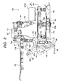
- a stopper bringing-down runner 112 is provided on a stud shaft 111 downwardly extending from the underside of the movable stand 103, and this stopper bringing-down runner 112 plays the role of pivotally moving the trailing end stopper portion 131 of the treating tray 130 to avoid the collision of the trailing end stopper portion 131 with the stapler 101, as will be described later.
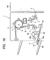
- the treating tray 130 is set in an inclined state by having its downstream side with respect to the direction of delivery of the sheet bundle (the left upper side as viewed in Figs. 5, 6A and 6B) positioned upwardly and having its upstream side (the right lower side as viewed in Figs. 5, 6A and 6B) positioned downwardly, and on the lower end portion thereof which is the upstream side, there are disposed sheet guides 130c disposed at predetermined intervals in the widthwise direction of the sheet, the knurled belt 190 and the trailing end stopper portion 131, and stack height detecting means 195 is provided near the trailing end stopper portion 131.
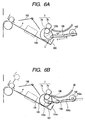
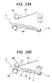
- the floating runner 191 is movable in a predetermined direction by moving means comprised of the traction arm 196 or the like. Traction means for the endless belt member is constituted by the floating runner and the moving means as described above.
- the traction arm 196 extends at a predetermined angle with respect to the treating tray 130 toward the trailing end stopper portion 131 of the treating tray below the pair of first delivery rollers 7, and has a rack portion 196a formed integrally therewith.
- the rack portion 196a and a gear portion 192a provided on the driving shaft of a motor 192 for traction are in engagement with each other.
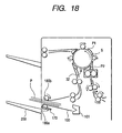
- the motor 192 for traction is a pulse motor, and is designed such that the amount of rotation of the motor is determined by a pulse signal given to the motor and the floating runner 191 is pulled by an amount conforming to the amount of rotation of the motor, whereby the distance h between the knurled belt 190 and the treating tray 130 shown in Fig. 6A is changed. That is, when the floating runner 191 is traction-operated in the direction indicated by the arrow X in Fig. 6A by the motor 192 for traction, the knurled belt 190 separates from the treating tray and the sheet bundle and is deformed and retracted (indicated by the broken line in Fig.
- design may be made such that the height position of the knurled belt 190 need not be changed for each sheet, but is changed for each plural sheets (e.g. each five sheets or each ten sheets).
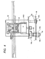
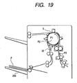
- the swingable guide 150 pivotally supports the upper delivery roller 180b contacting with the lower delivery roller 180a of the pair of bundle delivery rollers 180 in the front end portion of the underside corresponding to the downstream side (the left side as viewed in Fig. 5), and is pivotally supported and swingably supported by a support shaft 151 on the rear end portion of the underside corresponding to the upstream side (the right side as viewed in Fig. 5), and is swingable by the controlled driving of a rotary cam 152 by a driving motor M150, and a closed state in which the upper delivery roller 180b is in contact with the lower delivery roller 180a is the home position thereof, and a position sensor, not shown, for detecting the home position is provided.
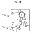
- the rotational output of the stepping motor M200 is transmitted to a pulley 212 on a driving shaft 213 through a timing belt 211.
- a ratchet wheel 215 biased by a spring 216 and only axially slidable is provided on the driving shaft 213, and this ratchet wheel 215 is one-way-engaged with a driving gear 214 on the shaft.
- One of idler gears 218 disposed on the opposite end portions of a driven shaft 217 is in meshing engagement with the driving gear 214, and the idler gears 218 are in meshing engagement with the rack gear members 251 through lift gear 219. That is, the stacking tray 200 is made vertically movable through a driving system comprising these gear trains.
- the ratchet wheel 215 one-way-engaged with the driving gear 214 on the driving shaft 213 is provided so that during the downward movement of the stacking tray 200, the driving system may not be damaged, for example, with foreign materials interposed, and herein, a required degree of biasing force is given to the spring 216 so that only during the upward movement of the stacking tray 200, the ratchet wheel may idly rotate against the biasing force of the spring 216 correspondingly to preset conditions to thereby protect the driving system, and when such idle rotation, i.e., an abnormality, occurs, a clock slit or the like formed in the flange portion of the idler gear 218 may be immediately detected by a sensor S201 to stop the driving of the stepping motor M200.
- the sensor S201 is also used for the detection of a step out during the ordinary operation.
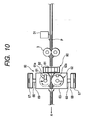
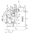
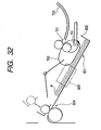
- Fig. 10 is a side illustration of the punch unit
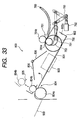
- Fig. 11 is a side illustration showing the operative state of the punch unit
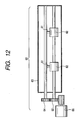
- Fig. 12 is a front illustration of the punch unit
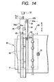
- Figs. 13 and 14 are illustrations of the lateral registration sensor moving mechanism of the punch unit.
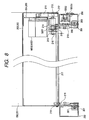
- the pair of second delivery rollers 9 are rotatively driven at a speed suited for stacking to thereby deliver the sheet P onto the sample tray 201 and cause it to be stacked thereon.
- bundle stacking is effected on the stacking tray 200 while the aligning position is changed for each sheet bundle, and the sort stacking by an offset amount L becomes possible.
Landscapes
- Engineering & Computer Science (AREA)
- Mechanical Engineering (AREA)
- Pile Receivers (AREA)
- Folding Of Thin Sheet-Like Materials, Special Discharging Devices, And Others (AREA)
Applications Claiming Priority (2)
| Application Number | Priority Date | Filing Date | Title |
|---|---|---|---|
| JP2000157888 | 2000-05-29 | ||
| JP2000157888A JP3728178B2 (ja) | 2000-05-29 | 2000-05-29 | シート処理装置及び画像形成装置 |
Publications (3)
| Publication Number | Publication Date |
|---|---|
| EP1160099A2 EP1160099A2 (en) | 2001-12-05 |
| EP1160099A3 EP1160099A3 (en) | 2003-12-10 |
| EP1160099B1 true EP1160099B1 (en) | 2006-10-11 |
Family
ID=18662439
Family Applications (1)
| Application Number | Title | Priority Date | Filing Date |
|---|---|---|---|
| EP01112793A Expired - Lifetime EP1160099B1 (en) | 2000-05-29 | 2001-05-28 | Sheet treating apparatus |
Country Status (4)
| Country | Link |
|---|---|
| US (1) | US6702279B2 (enExample) |
| EP (1) | EP1160099B1 (enExample) |
| JP (1) | JP3728178B2 (enExample) |
| DE (1) | DE60123702T2 (enExample) |
Cited By (1)
| Publication number | Priority date | Publication date | Assignee | Title |
|---|---|---|---|---|
| US9409735B2 (en) | 2013-08-06 | 2016-08-09 | Canon Kabushiki Kaisha | Sheet processing apparatus and image forming apparatus |
Families Citing this family (25)
| Publication number | Priority date | Publication date | Assignee | Title |
|---|---|---|---|---|
| US6231045B1 (en) * | 1998-06-12 | 2001-05-15 | Ricoh Company, Ltd. | Finisher for an image forming apparatus |
| JP4208502B2 (ja) * | 2002-06-28 | 2009-01-14 | キヤノン株式会社 | シート処理装置及び画像形成装置 |
| JP4086620B2 (ja) * | 2002-10-28 | 2008-05-14 | キヤノン株式会社 | シート処理装置およびこれを備えた画像形成装置 |
| US20040183249A1 (en) * | 2003-03-17 | 2004-09-23 | Fuji Xerox Co., Ltd. | Sheet processing apparatus and sheet bundle alignment method |
| JP2005350189A (ja) * | 2004-06-09 | 2005-12-22 | Canon Finetech Inc | シート積載装置及び該装置を備えた画像形成装置 |
| JP2006040445A (ja) * | 2004-07-28 | 2006-02-09 | Toshiba Corp | 光ディスク及び情報再生装置 |
| JP5112626B2 (ja) | 2004-11-25 | 2013-01-09 | オセ−テクノロジーズ・ベー・ヴエー | シート排出システム |
| US7461837B2 (en) * | 2005-03-15 | 2008-12-09 | Takashi Saito | Sheet discharging device and sheet postprocess apparatus using the same |
| JP4759345B2 (ja) * | 2005-08-31 | 2011-08-31 | キヤノン株式会社 | シート処理装置、および画像形成装置 |
| US8020857B2 (en) * | 2005-09-15 | 2011-09-20 | Toshiba Tec Kabushiki Kaisha | Paper sheet processing apparatus, and paper sheet processing method |
| US7571904B2 (en) * | 2006-12-07 | 2009-08-11 | Xerox Corporation | Control system for indexing compiler drive shaft that senses drive torque to initiate indexing |
| US7578498B2 (en) * | 2007-06-13 | 2009-08-25 | Kabushiki Kaisha Toshiba | Sheet processing apparatus and sheet processing method |
| US8132804B2 (en) | 2007-06-19 | 2012-03-13 | Kabushiki Kaisha Toshiba | Sheet processing apparatus |
| US7946568B2 (en) * | 2007-11-08 | 2011-05-24 | Canon Kabushiki Kaisha | Sheet processing apparatus and image forming apparatus having movable stopper with two conveyors |
| JP4594406B2 (ja) * | 2008-03-07 | 2010-12-08 | シャープ株式会社 | 後処理装置 |
| US8042796B2 (en) * | 2008-07-08 | 2011-10-25 | Kabushiki Kaisha Toshiba | Sheet finishing apparatus, sheet punching apparatus and control method |
| JP5506334B2 (ja) * | 2009-11-04 | 2014-05-28 | キヤノン株式会社 | シート処理装置 |
| JP5997495B2 (ja) * | 2012-05-01 | 2016-09-28 | キヤノン株式会社 | シート搬送装置およびそれを備えた画像形成システム |
| KR20160026255A (ko) * | 2014-08-29 | 2016-03-09 | 삼성전자주식회사 | 후처리장치 및 이를 포함하는 화상형성장치 |
| US10562731B2 (en) * | 2016-12-09 | 2020-02-18 | Canon Finetech Nisca Inc. | Apparatus for processing sheets and apparatus for forming images provided with the apparatus |
| US10604369B2 (en) * | 2016-12-09 | 2020-03-31 | Canon Finetech Nisca Inc. | Apparatus for processing sheets and apparatus for forming images provided with the apparatus |
| US10987964B2 (en) * | 2018-03-22 | 2021-04-27 | Fuji Xerox Co., Ltd. | Post-processing apparatus |
| EP3793836B1 (en) | 2018-05-15 | 2024-09-18 | Hewlett-Packard Development Company, L.P. | Finishing device comprising a paddle roller |
| JP7387374B2 (ja) | 2019-10-11 | 2023-11-28 | キヤノン株式会社 | シート処理装置及び画像形成システム |
| JP7642365B2 (ja) * | 2020-12-23 | 2025-03-10 | キヤノン株式会社 | 排紙装置及び画像形成装置 |
Family Cites Families (14)
| Publication number | Priority date | Publication date | Assignee | Title |
|---|---|---|---|---|
| JP2714289B2 (ja) | 1991-11-18 | 1998-02-16 | キヤノン株式会社 | シート後処理装置及び画像形成装置 |
| US5443248A (en) | 1992-06-29 | 1995-08-22 | Canon Kabushiki Kaisha | Sheet post-processing apparatus |
| JPH06286936A (ja) | 1993-04-07 | 1994-10-11 | Canon Inc | ジャム処理容易なシート後処理装置 |
| JP3696893B2 (ja) | 1993-04-07 | 2005-09-21 | キヤノン株式会社 | シート束移送手段を備えるシート後処理装置 |
| JP3040904B2 (ja) | 1993-12-24 | 2000-05-15 | キヤノン株式会社 | シート後処理装置及びこれを備える画像形成装置 |
| US5951000A (en) | 1994-03-18 | 1999-09-14 | Canon Kabushiki Kaisha | Sheet post-processing apparatus |
| JP3214656B2 (ja) | 1995-03-31 | 2001-10-02 | キヤノン株式会社 | シート後処理装置及びこれを備える画像形成装置 |
| JP3278044B2 (ja) | 1996-11-29 | 2002-04-30 | キヤノン株式会社 | シート処理装置及びこれを備える画像形成装置 |
| JP3193894B2 (ja) * | 1997-11-17 | 2001-07-30 | キヤノン株式会社 | シート処理装置及びこれを備える画像形成装置 |
| JP3416691B2 (ja) * | 1997-11-17 | 2003-06-16 | キヤノン株式会社 | シート処理装置及びこれを備える画像形成装置 |
| JP3740280B2 (ja) * | 1998-05-20 | 2006-02-01 | キヤノン株式会社 | シート処理装置及びこれを備える画像形成装置 |
| JP4124857B2 (ja) * | 1998-05-22 | 2008-07-23 | キヤノンファインテック株式会社 | シート処理装置及びこれを備える画像形成装置 |
| JP3526226B2 (ja) * | 1998-11-11 | 2004-05-10 | キヤノン株式会社 | シート処理装置及びこれを備える画像形成装置 |
| US6412774B1 (en) * | 1999-06-11 | 2002-07-02 | Nisca Corporation | Sheet receiving apparatus |
-
2000
- 2000-05-29 JP JP2000157888A patent/JP3728178B2/ja not_active Expired - Fee Related
-
2001
- 2001-05-28 DE DE60123702T patent/DE60123702T2/de not_active Expired - Lifetime
- 2001-05-28 EP EP01112793A patent/EP1160099B1/en not_active Expired - Lifetime
- 2001-05-29 US US09/865,547 patent/US6702279B2/en not_active Expired - Lifetime
Cited By (1)
| Publication number | Priority date | Publication date | Assignee | Title |
|---|---|---|---|---|
| US9409735B2 (en) | 2013-08-06 | 2016-08-09 | Canon Kabushiki Kaisha | Sheet processing apparatus and image forming apparatus |
Also Published As
| Publication number | Publication date |
|---|---|
| US20020008350A1 (en) | 2002-01-24 |
| US6702279B2 (en) | 2004-03-09 |
| EP1160099A2 (en) | 2001-12-05 |
| JP3728178B2 (ja) | 2005-12-21 |
| DE60123702D1 (de) | 2006-11-23 |
| EP1160099A3 (en) | 2003-12-10 |
| DE60123702T2 (de) | 2007-08-30 |
| JP2001335227A (ja) | 2001-12-04 |
Similar Documents
| Publication | Publication Date | Title |
|---|---|---|
| EP1160099B1 (en) | Sheet treating apparatus | |
| JP3526226B2 (ja) | シート処理装置及びこれを備える画像形成装置 | |
| EP0959034B1 (en) | Sheet treating apparatus and image forming apparatus therewith | |
| JP3559718B2 (ja) | シート処理装置及びこれを備えた画像形成装置 | |
| JPH11147641A (ja) | シート処理装置及びこれを備える画像形成装置 | |
| US20190248615A1 (en) | Sheet stacking apparatus and image forming system | |
| US20080258373A1 (en) | Post-processing apparatus and image forming system | |
| JP4962146B2 (ja) | 用紙処理装置 | |
| JP5011063B2 (ja) | 用紙搬送装置、給紙装置、用紙処理装置及び画像形成装置 | |
| JP3542474B2 (ja) | シート処理装置及びこれを備える画像形成装置 | |
| JP2001335236A (ja) | シート処理装置及びこれを備えた画像形成装置 | |
| JP4208370B2 (ja) | シート処理装置及びこれを備える画像形成装置 | |
| JP3193894B2 (ja) | シート処理装置及びこれを備える画像形成装置 | |
| JP4063659B2 (ja) | 用紙搬送装置、用紙処理装置及び画像形成システム | |
| EP0850866B1 (en) | Sheet processing apparatus | |
| JP3453502B2 (ja) | シート処理装置及びこれを備える画像形成装置 | |
| JPH11147654A (ja) | シート処理装置及びこれを備える画像形成装置 | |
| JP3416691B2 (ja) | シート処理装置及びこれを備える画像形成装置 | |
| JPH11320494A (ja) | シート穿孔装置及びこれを備えたシート処理装置並びに画像形成装置 | |
| JP2009173379A (ja) | 画像形成システム及び当該システムにおける用紙搬送方法 | |
| JP4081076B2 (ja) | シート後処理装置 | |
| JP3645009B2 (ja) | 後処理装置 | |
| JPH11334973A (ja) | シート処理装置及びこれを備える画像形成装置 | |
| JP2003276933A (ja) | シート処理装置 | |
| JP2024074127A (ja) | シート処理装置並びに画像形成システム |
Legal Events
| Date | Code | Title | Description |
|---|---|---|---|
| PUAI | Public reference made under article 153(3) epc to a published international application that has entered the european phase |
Free format text: ORIGINAL CODE: 0009012 |
|
| AK | Designated contracting states |
Kind code of ref document: A2 Designated state(s): AT BE CH CY DE DK ES FI FR GB GR IE IT LI LU MC NL PT SE TR |
|
| AX | Request for extension of the european patent |
Free format text: AL;LT;LV;MK;RO;SI |
|
| PUAL | Search report despatched |
Free format text: ORIGINAL CODE: 0009013 |
|
| AK | Designated contracting states |
Kind code of ref document: A3 Designated state(s): AT BE CH CY DE DK ES FI FR GB GR IE IT LI LU MC NL PT SE TR |
|
| AX | Request for extension of the european patent |
Extension state: AL LT LV MK RO SI |
|
| 17P | Request for examination filed |
Effective date: 20040608 |
|
| AKX | Designation fees paid |
Designated state(s): DE FR GB IT |
|
| 17Q | First examination report despatched |
Effective date: 20050309 |
|
| GRAP | Despatch of communication of intention to grant a patent |
Free format text: ORIGINAL CODE: EPIDOSNIGR1 |
|
| GRAS | Grant fee paid |
Free format text: ORIGINAL CODE: EPIDOSNIGR3 |
|
| GRAA | (expected) grant |
Free format text: ORIGINAL CODE: 0009210 |
|
| AK | Designated contracting states |
Kind code of ref document: B1 Designated state(s): DE FR GB IT |
|
| PG25 | Lapsed in a contracting state [announced via postgrant information from national office to epo] |
Ref country code: IT Free format text: LAPSE BECAUSE OF FAILURE TO SUBMIT A TRANSLATION OF THE DESCRIPTION OR TO PAY THE FEE WITHIN THE PRESCRIBED TIME-LIMIT;WARNING: LAPSES OF ITALIAN PATENTS WITH EFFECTIVE DATE BEFORE 2007 MAY HAVE OCCURRED AT ANY TIME BEFORE 2007. THE CORRECT EFFECTIVE DATE MAY BE DIFFERENT FROM THE ONE RECORDED. Effective date: 20061011 |
|
| REG | Reference to a national code |
Ref country code: GB Ref legal event code: FG4D |
|
| REF | Corresponds to: |
Ref document number: 60123702 Country of ref document: DE Date of ref document: 20061123 Kind code of ref document: P |
|
| ET | Fr: translation filed | ||
| PLBE | No opposition filed within time limit |
Free format text: ORIGINAL CODE: 0009261 |
|
| STAA | Information on the status of an ep patent application or granted ep patent |
Free format text: STATUS: NO OPPOSITION FILED WITHIN TIME LIMIT |
|
| 26N | No opposition filed |
Effective date: 20070712 |
|
| REG | Reference to a national code |
Ref country code: FR Ref legal event code: PLFP Year of fee payment: 16 |
|
| REG | Reference to a national code |
Ref country code: FR Ref legal event code: PLFP Year of fee payment: 17 |
|
| PGFP | Annual fee paid to national office [announced via postgrant information from national office to epo] |
Ref country code: DE Payment date: 20170531 Year of fee payment: 17 Ref country code: GB Payment date: 20170517 Year of fee payment: 17 Ref country code: FR Payment date: 20170524 Year of fee payment: 17 |
|
| REG | Reference to a national code |
Ref country code: DE Ref legal event code: R119 Ref document number: 60123702 Country of ref document: DE |
|
| GBPC | Gb: european patent ceased through non-payment of renewal fee |
Effective date: 20180528 |
|
| PG25 | Lapsed in a contracting state [announced via postgrant information from national office to epo] |
Ref country code: FR Free format text: LAPSE BECAUSE OF NON-PAYMENT OF DUE FEES Effective date: 20180531 Ref country code: DE Free format text: LAPSE BECAUSE OF NON-PAYMENT OF DUE FEES Effective date: 20181201 Ref country code: GB Free format text: LAPSE BECAUSE OF NON-PAYMENT OF DUE FEES Effective date: 20180528 |