EP1160044A2 - Werkzeug zum drehenden Reibungschweissen und drehendes Reibungschweissverfahren unter Verwendung desselben - Google Patents
Werkzeug zum drehenden Reibungschweissen und drehendes Reibungschweissverfahren unter Verwendung desselben Download PDFInfo
- Publication number
- EP1160044A2 EP1160044A2 EP01113064A EP01113064A EP1160044A2 EP 1160044 A2 EP1160044 A2 EP 1160044A2 EP 01113064 A EP01113064 A EP 01113064A EP 01113064 A EP01113064 A EP 01113064A EP 1160044 A2 EP1160044 A2 EP 1160044A2
- Authority
- EP
- European Patent Office
- Prior art keywords
- probe
- joining
- joining members
- rotor
- groove
- Prior art date
- Legal status (The legal status is an assumption and is not a legal conclusion. Google has not performed a legal analysis and makes no representation as to the accuracy of the status listed.)
- Granted
Links
- 238000013019 agitation Methods 0.000 title claims abstract description 56
- 238000000034 method Methods 0.000 title claims abstract description 34
- 238000003756 stirring Methods 0.000 title 1
- 239000000523 sample Substances 0.000 claims abstract description 254
- 230000002093 peripheral effect Effects 0.000 claims abstract description 40
- 239000000463 material Substances 0.000 description 23
- 238000007254 oxidation reaction Methods 0.000 description 19
- 230000006866 deterioration Effects 0.000 description 8
- 230000003247 decreasing effect Effects 0.000 description 5
- 229910052751 metal Inorganic materials 0.000 description 5
- 239000002184 metal Substances 0.000 description 5
- 239000000203 mixture Substances 0.000 description 5
- 230000007423 decrease Effects 0.000 description 4
- 238000003780 insertion Methods 0.000 description 4
- 230000037431 insertion Effects 0.000 description 4
- 239000010419 fine particle Substances 0.000 description 3
- 239000000956 alloy Substances 0.000 description 2
- 229910045601 alloy Inorganic materials 0.000 description 2
- 229910052782 aluminium Inorganic materials 0.000 description 2
- XAGFODPZIPBFFR-UHFFFAOYSA-N aluminium Chemical compound [Al] XAGFODPZIPBFFR-UHFFFAOYSA-N 0.000 description 2
- 230000014509 gene expression Effects 0.000 description 2
- 230000003647 oxidation Effects 0.000 description 2
- 239000000843 powder Substances 0.000 description 2
- 238000003825 pressing Methods 0.000 description 2
- 230000008961 swelling Effects 0.000 description 2
- 238000003466 welding Methods 0.000 description 2
- 230000000994 depressogenic effect Effects 0.000 description 1
- 239000007769 metal material Substances 0.000 description 1
- 238000012986 modification Methods 0.000 description 1
- 230000004048 modification Effects 0.000 description 1
- 239000012071 phase Substances 0.000 description 1
- 239000007790 solid phase Substances 0.000 description 1
Images




Classifications
-
- B—PERFORMING OPERATIONS; TRANSPORTING
- B23—MACHINE TOOLS; METAL-WORKING NOT OTHERWISE PROVIDED FOR
- B23K—SOLDERING OR UNSOLDERING; WELDING; CLADDING OR PLATING BY SOLDERING OR WELDING; CUTTING BY APPLYING HEAT LOCALLY, e.g. FLAME CUTTING; WORKING BY LASER BEAM
- B23K20/00—Non-electric welding by applying impact or other pressure, with or without the application of heat, e.g. cladding or plating
- B23K20/12—Non-electric welding by applying impact or other pressure, with or without the application of heat, e.g. cladding or plating the heat being generated by friction; Friction welding
- B23K20/122—Non-electric welding by applying impact or other pressure, with or without the application of heat, e.g. cladding or plating the heat being generated by friction; Friction welding using a non-consumable tool, e.g. friction stir welding
- B23K20/1245—Non-electric welding by applying impact or other pressure, with or without the application of heat, e.g. cladding or plating the heat being generated by friction; Friction welding using a non-consumable tool, e.g. friction stir welding characterised by the apparatus
- B23K20/1255—Tools therefor, e.g. characterised by the shape of the probe
Definitions
- the present invention relates to a friction agitation joining tool used for welding joining members made of metal such as aluminum or its alloy, and also relates to a friction agitation joining method using the aforementioned joining tool.
- a friction agitation joining method is classified into a solid-phase welding method, and has advantages such that the method can be applied to any kinds of metallic materials and that the method causes fewer thermal strain due to joining.
- the friction agitation joining method is used at various assembling sites of structures, such as vessels, automobiles, railroad cars and panel structures.
- Fig. 5 shows two plate-shaped metal joining members which are being butt-joined by a friction agitation joining method.
- the reference numerals 101 and 102 denote plate-shaped metal joining members. Both the joining members 101 and 102 have the same thickness, and are disposed in a butted state.
- the reference numeral 110 denotes a friction agitation joining tool.
- the joining tool 110 is equipped with a column-shaped rotor 111 and a pin-shaped probe 112 having a diameter smaller than a diameter of the probe.
- the pin-shaped probe 112 is projected from a part of the end face 111a of the rotor 111.
- agitating projections are formed on the peripheral surface of the entire length of the probe 112.
- the probe 112 When joining both the joining members 101 and 102 in a butted state with the aforementioned joining tool 110, the probe 112 is rotated in accordance with the rotation of the rotor 111. Then, the rotating probe 112 is inserted into the butted portion 103 of both the joining members 101 and 102, and the end face 111a of the rotating rotor 111 is forced to be pressed on the surface of both the joining members 101 and 102. While keeping this state, the probe 112 is advanced relative to both the joining members 101 and 102 along the butted portion 103.
- both the joining members 101 and 102 where the probe 112 contacts and its vicinity will be softened by the frictional heat generated due to the rotation of the probe 112 and the contact between the end face 111a of the rotor 111 and the surface of the joining members 101 and 102.
- the softened and agitated materials of the joining members 101 and 102 are plastically fulidized to go around the probe 112 and to fill up a groove formed behind the probe 112 as it moves. Then, the materials will be cooled and solidified by the immediate loss of such friction heat. This phenomenon will be repeated with the advancing movement of the probe 112, which causes the joining members 101 and 102 to be integrally joined along the entire length of the butted portion 103.
- the reference numeral 109 denotes the joined portion of the joining members 101 and 102.
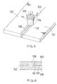
- Fig. 6 shows the stacked two joining members joined by the aforementioned joining tool 110.
- the reference numerals 105 and 106 denote plate-shaped metal joining members, respectively. Both joining members 105 and 106 are stacked one on top of the other.
- the reference numeral 107 denotes the superposed interface of the joining members 105 and 106.
- the probe 112 is provided with the aforementioned agitating protrusions on the peripheral surface of the entire length thereof.
- the rotating probe 112 is inserted into both the joining members 105 and 106 from the upper surface of the upper joining member 105, the materials of the upper and lower joining members 105 and 106 softened by the frictional heat will be stirred up by the agitating protrusions. Thereby, the upper surface of the upper joining member 105 swells.
- the upper surface of the upper joining member 105 is pressed down by the end face 111a of the rotor 111 to be flattened. Consequently, the thickness of the joined portion 109 of the upper joining member 105 and its vicinity decreases. This deteriorates the strength of the joined members.
- natural-oxidation films 105a and 106a are usually formed in the superposed interface of the joining member 105 and 106 as shown in Fig. 7A, the natural-oxidation films 105a and 106a will be stirred up by the agitating protrusions at the time of joining. Thus, as shown in Fig. 7B, the natural-oxidation films near the joined portion 109 will be raised. This causes an easy generation of fatigue cracks, resulting in a deterioration of fatigue strength of the obtained stacked joint.
- the object of the present invention is to provide a friction agitation joining tool which can prevent a deterioration of strength of the joined members, such as a deterioration of joined strength and fatigue strength, to obtain a joined member having strength reliability, and also to provide a friction agitation joining method using such a joining tool.
- a friction agitation joining tool includes a rotor and a probe to be inserted into joining members, wherein the probe has a diameter smaller than a diameter of the rotor and is provided at a part of an end surface of the rotor, wherein the probe is provided with a groove formed on a peripheral surface of at least a longitudinal middle portion of the probe. the groove extending in an axial direction of the probe.
- the probe is inserted into two pieces of metal joining members stacked one on top of the other such that the probe crosses both of the joining members.
- the groove is disposed generally perpendicular to the superposed interface of the stacked joining members.
- the natural-oxidation films formed on the superposed interface of each joining member will be ground minutely with the edge of the groove. Consequently, the standup of the natural-oxidation film which may occur near the joined portion will be suppressed, which enhances the fatigue strength of the obtained stacked joint.
- the groove is formed such that a width of the groove becomes gradually narrow toward a basal end of the probe.
- a width W of the groove so as to satisfy the following inequality: 5/100 ⁇ (W1-W2)/(2t0) ⁇ 15/100, where W1 is a width of one end of the groove at a tip end side of the probe, W2 is a width of the other end of the groove at a basal end side of the probe, and t0 is a total thickness of joining members.
- a width W of the groove so as to satisfy the following inequality: 1/20 ⁇ W/D2 ⁇ 1/8, where D2 is a diameter of the probe. This enables the natural-oxidation film to be completely ground into fine particles.
- a depth H of the groove so as to satisfy the following inequality: 0.5 ⁇ H/W ⁇ 1.5, where W is a width of the groove. This enables the natural-oxidation film to be completely ground into fine particles.
- a friction agitation joining tool includes a rotor, a probe to be inserted into joining members, wherein the probe has a diameter smaller than a diameter of the rotor and is provided at a part of an end surface of the rotor, and an agitating protrusion provided on a peripheral surface of the probe only in a region of from a basal end portion of the probe to a longitudinal middle portion of the probe.
- the probe is inserted into both the joining members stacked one on top of the other such that the probe crosses the two joining members, in the same manner as in the first aspect of the present invention. Furthermore, the end face of the rotor presses the outer surface of one of the joining members located at the basal end side of the probe.
- the agitating protrusion is provided only in the range of from the basal end portion of the probe to a longitudinal middle portion thereof, the protrusion is buried only in one of the joining members located at the basal end side of the probe, and is not buried in the other joining member located at the tip end side of the probe.
- the protrusion extends in a helical fashion.
- the materials of the joining members softened by frictional heat can be agitated efficiently.
- a friction agitation joining tool includes a rotor and a probe to be inserted into joining members, wherein the probe has a diameter smaller than a diameter of the rotor and is provided at a part of an end surface of the rotor, wherein the probe is provided with a groove extending in an axial direction of the probe on a peripheral surface of at least longitudinal middle portion of the probe, and wherein the probe is provided with an agitating protrusion on a peripheral surface of the probe only in a region of from a basal end portion of the probe to a longitudinal middle portion of the probe.
- the groove is formed such that a width of the groove becomes gradually narrow toward the basal end portion of the probe because of the aforementioned reasons.
- width W of the groove so as to satisfy the following inequality: 5/100 ⁇ (W1-W2)/(2t0) ⁇ 15/100, where W1 is a width of one end of the groove at a tip end side of the probe, W2 is a width of the other end of the groove at a basal end side of the probe, and t0 is a total thickness of joining members, because of the same reasons as mentioned above.
- the width W of the groove so as to satisfy the following inequality: 1/20 ⁇ W/D2 ⁇ 1/8, where D2 is a diameter of the probe, because of the same reasons as mentioned above.
- the depth H of the groove so as to satisfy the following inequality: 0.5 ⁇ H/W ⁇ 1.5, where W is a width of the groove, because of the same reasons as mentioned above.
- the protrusion extends in a helical fashion.
- a friction agitation joining tool includes a rotor and a probe to be inserted into joining members, wherein the probe has a diameter smaller than a diameter of the rotor and is provided at a part of an end surface of the rotor, wherein the probe includes a first shaft portion and a second shaft portion having a diameter smaller than a diameter of the first shaft portion, the first shaft portion constituting a region of from a basal end portion of the probe to a longitudinal middle portion of the probe, the second shaft portion constituting a region of from the longitudinal middle portion to a tip end portion of the probe, wherein the probe is provided with a groove extending in an axial direction of the probe on a peripheral surface of at least the longitudinal middle portion, and wherein the probe is provided with an agitating protrusion only on a peripheral surface of the first shaft portion.
- the same function as that of the joining tool according to the first aspect of the present invention and the same function as that of the joining tool according to the second aspect of the invention can be obtained simultaneously. Furthermore, a stepped portion formed between the first shaft portion and the second shaft portion presses the portion of the joining members softened by friction heat. Consequently, the materials of the joining members can be agitated much more effectively, resulting in a good joined portion.
- the groove is formed such that a width of the groove becomes gradually narrow toward the basal end portion of the probe, because of the same reasons as mentioned above.
- the width W of the groove so as to satisfy the following inequality: 5/100 ⁇ (W1-W2)/(2t0) ⁇ 15/100, where W1 is a width of one end of the groove at a tip end side of the probe, W2 is a width of the other end of the groove at a basal end side of the probe, and t0 is a total thickness of joining members, because of the same reasons as mentioned above.
- the width W of the groove so as to satisfy the following inequality: 1/20 ⁇ W/D2 ⁇ 1/8, where D2 is a diameter of the probe, because of the same reasons as mentioned above.
- the depth H of the groove so as to satisfy the following inequality: 0.5 ⁇ H/W ⁇ 1.5, where W is a width of the groove.
- the protrusion extends in a helical fashion, because of the same reasons as mentioned above.
- a peripheral surface of the first shaft portion and that of the second shaft portion are connected via a tapered surface.
- a taper angle of the tapered surface relative to an axis of the probe falls within the range of from 20° to 30°.
- a friction agitation joining method for joining stacked two joining members includes the steps of: preparing a friction agitation joining tool comprising a rotor and a probe to be inserted into the joining members, wherein the probe has a diameter smaller than a diameter of the rotor and is provided at a part of an end surface of the rotor, wherein the probe is provided with a groove formed on a peripheral surface of at least a longitudinal middle portion of the probe, the groove extending in an axial direction of the probe; inserting the rotating probe into the stacked two joining members such that the groove crosses a superposed interface of the joining members; and moving the rotating probe relative to the joining members with the rotating probe inserted in the joining members to thereby join the joining members.
- the groove comes to approximately perpendicularly cross the superposed interface of the joining members. Then, by moving the probe relative to the joining members while keeping the insertion state, the natural-oxidation film formed in the superposed interface will be ground minutely with this movement the probe. Consequently, the standup of the natural-oxidation film which may cause near the joined portion will be suppressed, resulting in an enhanced fatigue strength of the stacked joint.
- a friction agitation joining method for joining stacked two joining members including the steps of: preparing a friction agitation joining tool which comprises a rotor, a probe to be inserted into the joining members, the probe having a diameter smaller than a diameter of the rotor and being provided at a part of an end surface of the rotor, and an agitating protrusion provided on a peripheral surface of the probe only in a region of from a basal end portion of the probe to a longitudinal middle portion of the probe; inserting the rotating probe into the stacked two joining members such that the protrusion is buried only in one of the joining members located at the basal end portion side of the probe; and moving the rotating probe relative to the joining members with the rotating probe inserted in the joining members to thereby join the joining members.
- the agitating protrusion is buried only in one of the joining members located at the basal end portion side of the probe and is not buried in the other of the joining members located at the tip end portion side of the probe, it is prevented the materials at the tip end portion side of the probe from being stirred up by the protrusion.
- This decreases the swell of the outer surface of the joining member located at the basal end side of the probe. Accordingly, the deterioration of the joint strength due to the decreased thickness of the joining member at the probe basal end side can be suppressed.
- a friction agitation joining method for joining stacked two joining members includes the steps of: preparing a friction agitation joining tool which comprises a rotor and a probe to be inserted into joining members, wherein the probe has a diameter smaller than a diameter of the rotor and is provided at a part of an end surface of the rotor, wherein the probe is provided with a groove extending in an axial direction of the probe on a peripheral surface of at least longitudinal middle portion of the probe, and wherein the probe is provided with an agitating protrusion on a peripheral surface of the probe only in a region of from a basal end portion to a longitudinal middle portion of the probe; inserting the rotating probe into the stacked two joining members such that the groove crosses a superposed interface of the joining members and that the protrusion is buried only in one of the joining members located at the basal end portion side of the probe; and moving the probe relative to the joining members with the rotating probe inserted in the joining members to thereby join the
- a friction agitation joining method for joining stacked two joining members includes the steps of: preparing a friction agitation joining tool which comprises a rotor and a probe to be inserted into joining members, wherein the probe has a diameter smaller than a diameter of the rotor and is provided at a part of an end surface of the rotor, wherein the probe includes a first shaft portion and a second shaft portion having a diameter smaller than a diameter of the first shaft portion, the first shaft portion constituting a region of from a basal end portion of the probe to a longitudinal middle portion of the probe, the second shaft portion constituting a region of from the longitudinal middle portion to a tip end portion of the probe, wherein the probe is provided with a groove extending in an axial direction of the probe on a peripheral surface of at least the longitudinal middle portion, and wherein the probe is provided with an agitating protrusion only on a peripheral surface of the first shaft portion; inserting the rotating probe into the stacked two joining members such that
- the same function as that of the joining method according to the fifth aspect of the present invention and the same function as that of the joining method according to the sixth aspect of the invention can be obtained simultaneously. Furthermore, the stepped portion formed between the first shaft portion and the second shaft portion presses the portion of the joining members softened by the friction heat. As a result, the materials of the joining members can be more effectively agitated, resulting in a good joined portion.
- the reference numeral 10 denotes a friction agitation joining tool according to this embodiment.
- This joining tool 10 is equipped with a column-shaped rotor 11 and a pin-shaped probe 12 having a diameter smaller than the diameter of the rotor 11.
- the probe 12 is projected from the rotation center of the end face 11a of the rotor 11 along the rotation axis thereof.
- the rotor 11 and the probe 12 rotate integrally.
- the reference numerals 1 and 2 denote two joining members to be joined by the aforementioned joining tool 10.
- Each joining member 1 and 2 are plate-shaped aluminum or its alloy. Both the joining members 1 and 2 are arranged one on top of the other.
- the rotating probe 12 of the joining tool 10 is inserted into both the joining members 1 and 2 from the external surface of the upper joining member 1 such that the probe 12 crosses both the joining members 1 and 2.
- the end face 11a of the rotor 11 is pressing the external surface of the upper joining member 1 in a rotating state. In this state, the probe 12 is moved in the predetermined direction.
- the joining members 1 and 2 are continuously joined at the probe passing portion by the prove 12.
- the reference numeral 9 denotes a joined portion of both the joining members 1 and 2.
- the reference letter “Y” denotes a predetermined portion to be joined.
- the reference numeral 3 denotes the superposed interface of both the joining members 1 and 2.
- the rotor 11 and the probe 12 are made of heat resisting materials which are harder than the materials of both the joining members 1 and 2 and can resist against the frictional heat generated at the time of joining.
- the end face 11a of the rotor 11 is formed to be depressed from the periphery edge toward the rotation central portion. Furthermore, the corner portion between the peripheral surface of the rotor 11 and the end face 11a thereof is beveled so as not to blemish the external surface of the upper joining member 1 when the corner portion contacts thereto.
- the probe 12 includes a first shaft portion 12a and a second shaft portion 12b having a diameter smaller than a diameter of the first shaft portion.
- the first shaft portion 12a constitutes a region of from a basal end portion of the probe to a longitudinal middle portion of the probe.
- the second shaft portion 12b constitutes a region of from the longitudinal middle portion to a tip end portion of the probe.
- the first shaft portion 12a and the second shaft portion 12b are formed on the same axis. Furthermore, the peripheral surface of the first shaft portion 12a and that of the second shaft portion 12b are connected via a tapered surface.
- this probe 12 consists of the first shaft portion 12a and the second shaft portion 12b, the portion of the joining members softened by the frictional heat will be pressed by the stepped portion C formed between the first shaft portion 12a and the second shaft portion 12b at the time of joining. Accordingly, the materials of both the joining members 1 and 2 are effectively agitated, resulting in a good joined portion 9.
- an agitating protrusion 14 of a triangular cross-section extends in a helical manner along the entire length of the first shaft portion 12a.
- no such an agitating protrusion is provided on the peripheral surface of the second shaft portion 12b.
- This agitating protrusion 14 is provided so as to effectively perform an agitation mixture of the materials of both the joining members 1 and 2 softened by the frictional heat.
- the screw thread of M5 ⁇ 0.8 is formed on the peripheral surface of the first shaft portion 12a.
- This screw thread constitutes an agitating protrusion 14. Furthermore, between the adjacent agitating protrusions 14 in the direction of the probe axis, a dented portion 13 of a triangular cross-section is formed so as to extend in a helical manner similar to the protrusion.
- the helical direction of the agitating protrusion 14 is defined so that the probe 12 advances when the probe 12 rotates in the predetermined direction (in the rotation direction 20).
- the entire length L1 of the agitating protrusion forming portion of the probe 12 (namely, the entire length of the first shaft portion 12a) so as to satisfy the following inequality: 3/4 ⁇ L1/t1 ⁇ 1
- the value of L1/t1 is less than 3/4, when the probe 12 is inserted into both the joining members 1 and 2, the distance between the agitating protrusion 14 and the lower joining member 2 becomes too far to agitate the materials of both the joining members 1 and 2.
- the value of L1/t1 exceeds 1, when the probe 12 is inserted into both the joining members 1 and 2, a part of the agitating protrusion 14 will be embedded into the lower joining member 2. Therefore, it is desirable to set L1 so as to satisfy the following inequality: 3/4 ⁇ L1/t1 ⁇ 1.
- the peripheral surface of the first shaft portion 12a and that of the second shaft portion 12b are connected via the tapered surface as mentioned above, the first shaft portion 12a and the agitating protrusion 14 can be inserted into the upper joining member 1 smoothly and easily. Furthermore, it is preferable that the inclination angle of the aforementioned tapered surface relative to the probe axis falls within the range of from 20 to 30°. When the inclination angle is set as mentioned above, the first shaft portion 12a and the agitating protrusion 14 can be inserted into the upper joining member 1 more smoothly and easily.
- D2 of the first shaft portion 12a it is desirable to set the diameter D2 of the first shaft portion 12a so as to satisfy the following inequality: 0.27 ⁇ D2/D1 ⁇ 0.35, where D1 is the diameter of the rotor 11.
- D1 is the diameter of the rotor 11.
- D2 is set within the range of from 3.5 to 4.2mm
- D1 is set within the range of from 12 to 13mm.
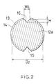
- two grooves 15 and 15 each having a triangular cross-section and extending parallel to the probe axis are formed at 180° phase difference along the entire length of the prove 12.
- Each groove 15 is designed so that the edge of the groove grinds the natural-oxidation film (see Fig. 7A, 105a and 106a) formed on the superposed interface of the joining members 1 and 2.
- the groove 15 since the groove 15 extends parallel to the probe axis, when the probe 12 is inserted into both the joining members 1 and 2, the groove 15 can be assuredly positioned so as to perpendicularly cross the superposed interface 3 of both the joining members 1 and 2. This can ground the natural oxidation film assuredly and certainly into minute pieces by the edge of the groove 15.
- the pulverized powder of the natural oxidation film will be dispersed in the softened portion of both the joining members 1 and 2 by the rotating force of the probe 12.
- this groove 15 is formed such that the width becomes narrow gradually in the direction of from the tip end to the basal end of the probe 12.
- a width W of the groove 15 so as to satisfy the following inequality: 5/100 ⁇ (W1-W2)/(2t0) ⁇ 15/100, where W1 is a width of one end of the groove at a tip end side of the probe, W2 is a width of the other end of the groove at a basal end side of the probe.
- the width W of the groove 15 so as to satisfy the following inequality: 1/20 ⁇ W/D2 ⁇ 1/8, where D2 is a diameter of said probe, and also to set the depth H of the groove 15 so as to satisfy the following inequality: 0.5 ⁇ H/W ⁇ 1.5, where W is a width of said groove.
- the rotor 11 is driven to rotate the probe 12. Then, the probe 12 is inserted into both the joining members 1 and 2 from the upper joining member 1 so as to cross both the joining members 1 and 2, and the end surface 11a of the rotor 11 is pressed onto the outer surface of the upper joining member 1.
- the groove 15 crosses the superposed interface 3 of the joining members 1 and 2 perpendicularly, and the protrusion 14 will be buried only in the upper joining member 1.
- the probe 12 can be inserted smoothly and easily.
- the rotor 11 is slightly leaned toward the direction opposite to the joining direction. In this state, the probe 12 is moved along the predetermined joining portion Y. In the meantime, needless to say, the probe 12 may be inserted into both the joining members 1 and 2 from the end surface thereof.
- the frictional heat generated in accordance with the rotation of the probe 12 and the frictional heat generated in accordance with the slide between the end surface 11a of the rotor 11 and the outer surface of the upper joining member 1 softens a portion of both the joining members 1 and 2 near the probe. Furthermore, the natural-oxidation film formed in the superposed interface of the joining members 1 and 2 will be ground minutely by the edge of the groove 15, and this pulverized powder will be dispersed into the softened portion of the joining members 1 and 2 softened by the frictional heat. In this state, both the joining members 1 and 2 will be agitated by the probe 12.
- the agitating protrusion 14 is provided on the peripheral surface of the first shaft portion 12a of the probe 12, the agitation mixture is performed effectively. Furthermore, the softened portion of the joining members 1 and 2 is pressurized by the stepped portion C. As a result, the agitation mixture will be performed much more effectively. Furthermore, since the agitating protrusion 14 is buried only in the upper joining member 1 and is not buried in the lower joining member 2, it is prevented that materials of the lower joining member 2 is stirred up. Thus, the swelling of the outer surface of the upper joining member 1 can be decreased. On the other hand, the outer surface of the swelled upper joining member 1 will be pressed by the end surface 11a of the rotor 11 to be flattened.
- the thickness of the upper joining member 1 hardly decreases and maintains the original thickness.
- the softened and agitated materials of the joining members 1 and 2 are plastically fluidized to go around the probe 12 and to fill up a groove formed behind the probe 12 as it moves. Then, the materials will be cooled and solidified by the immediate loss of such friction heat. This phenomenon will be repeated with the advancing movement of the probe 12, which causes the joining members 1 and 2 to be integrally joined along the probe passed portion.
- the joint is also high in strength.
- the friction agitation joining tool according to the present invention is not limited to the aforementioned embodiment and can be modified variously.
- one groove 15 or three or more grooves 15 may be formed. Especially, it is preferable to provide one to four grooves 15.
- the groove 15 is provided on the peripheral surface of the probe 12 along the entire length thereof, according to the present invention, the groove 15 may be provided only in the middle portion in the direction of the probe axis.
- the friction agitation joining method according to the present invention is not limited the aforementioned embodiment, and may be changed in various manners.
- the joining operation is performed by moving the probe 12 inserted in both the joining members 1 and 2.
- both the joining members 1 and 2 may be moved.
- the natural-oxidation film formed in the superposed interface of each joining member can be ground minutely by the edge of the groove, and the standup of the natural-oxidation film which may be generated near the joined portion can be suppressed. As a result, the fatigue strength of the stacked joining can be increased.
- the fatigue strength and the joint strength of the stacked joint can be increased.
- the softened portion of both the joining members softened by the frictional heat can be pressurized by the step portion formed between the first shaft portion and the second shaft portion, the materials of both the joining members can be agitated effectively. This causes a good joined portion, resulting in further enhanced fatigue strength and joint strength of the stacked joint.
Landscapes
- Engineering & Computer Science (AREA)
- Mechanical Engineering (AREA)
- Pressure Welding/Diffusion-Bonding (AREA)
- Accessories For Mixers (AREA)
Applications Claiming Priority (2)
| Application Number | Priority Date | Filing Date | Title |
|---|---|---|---|
| JP2000161528A JP2001340976A (ja) | 2000-05-31 | 2000-05-31 | 摩擦撹拌接合工具及び摩擦撹拌接合法 |
| JP2000161528 | 2000-05-31 |
Publications (3)
| Publication Number | Publication Date |
|---|---|
| EP1160044A2 true EP1160044A2 (de) | 2001-12-05 |
| EP1160044A3 EP1160044A3 (de) | 2004-01-02 |
| EP1160044B1 EP1160044B1 (de) | 2007-10-24 |
Family
ID=18665542
Family Applications (1)
| Application Number | Title | Priority Date | Filing Date |
|---|---|---|---|
| EP01113064A Expired - Lifetime EP1160044B1 (de) | 2000-05-31 | 2001-05-29 | Werkzeug zum drehenden Reibungschweissen und drehendes Reibungschweissverfahren unter Verwendung desselben |
Country Status (4)
| Country | Link |
|---|---|
| US (1) | US6510975B2 (de) |
| EP (1) | EP1160044B1 (de) |
| JP (1) | JP2001340976A (de) |
| DE (1) | DE60131045T2 (de) |
Cited By (6)
| Publication number | Priority date | Publication date | Assignee | Title |
|---|---|---|---|---|
| US6510975B2 (en) * | 2000-05-31 | 2003-01-28 | Showa Denko K.K. | Friction agitation joining tool and friction agitation joining method using the same |
| US7717314B2 (en) | 2005-02-01 | 2010-05-18 | Airbus Uk Limited | Friction stir welding tool |
| CN102581475A (zh) * | 2012-03-22 | 2012-07-18 | 哈尔滨工业大学 | 倾角可调且轴肩呈上凹下凸式搅拌摩擦焊的焊具及方法 |
| CN102601514A (zh) * | 2012-03-22 | 2012-07-25 | 哈尔滨工业大学 | 轴肩呈上凹下凹式焊具及无支撑无倾角搅拌摩擦焊方法 |
| CN104400215A (zh) * | 2014-11-26 | 2015-03-11 | 哈尔滨工业大学 | 一种减小界面缺陷尺寸的搅拌摩擦搭接焊用搅拌头及其焊接方法 |
| CN113953654A (zh) * | 2021-11-23 | 2022-01-21 | 湖南坤鼎数控科技有限公司 | 一种搅拌摩擦焊搅拌头 |
Families Citing this family (32)
| Publication number | Priority date | Publication date | Assignee | Title |
|---|---|---|---|---|
| US6676004B1 (en) * | 2001-02-13 | 2004-01-13 | Edison Welding Institute, Inc. | Tool for friction stir welding |
| US6726084B2 (en) * | 2001-06-15 | 2004-04-27 | Lockheed Martin Corporation | Friction stir heating/welding with pin tool having rough distal region |
| JP2003039181A (ja) * | 2001-07-24 | 2003-02-12 | Hitachi Ltd | 摩擦攪拌接合方法および回転工具 |
| US6659331B2 (en) * | 2002-02-26 | 2003-12-09 | Applied Materials, Inc | Plasma-resistant, welded aluminum structures for use in semiconductor apparatus |
| US6676008B1 (en) * | 2002-04-30 | 2004-01-13 | Edison Welding Institute | Friction stir welding of corner configurations |
| JP4134837B2 (ja) * | 2003-07-15 | 2008-08-20 | マツダ株式会社 | 摩擦接合方法および摩擦接合構造 |
| JP4695355B2 (ja) * | 2004-07-15 | 2011-06-08 | 新日本製鐵株式会社 | 溶接部疲労強度に優れる建設機械のブーム・アーム部材およびその製造方法 |
| US7857192B2 (en) | 2006-03-16 | 2010-12-28 | Showa Denko K.K. | Friction stir welding tool and friction stir welding method |
| US20080217377A1 (en) * | 2007-03-06 | 2008-09-11 | Alcoa Inc. | Fracture Resistant Friction Stir Welding Tool |
| US7942306B2 (en) * | 2007-04-13 | 2011-05-17 | Wichita State University | Friction stir welding tool having a counterflow pin configuration |
| US7793816B2 (en) * | 2007-09-07 | 2010-09-14 | Alcoa Inc. | Friction stir welding apparatus |
| US7854362B2 (en) | 2008-03-14 | 2010-12-21 | Alcoa Inc. | Advanced multi-shouldered fixed bobbin tools for simultaneous friction stir welding of multiple parallel walls between parts |
| JP4755236B2 (ja) * | 2008-09-29 | 2011-08-24 | 三菱重工業株式会社 | 摩擦攪拌接合方法 |
| JP4782186B2 (ja) * | 2008-12-15 | 2011-09-28 | 三菱重工業株式会社 | 重ね摩擦攪拌接合方法及びその方法で製造された構造体 |
| DE102009008328A1 (de) * | 2009-02-10 | 2010-08-12 | Technische Universität Braunschweig Carolo-Wilhelmina | Verfahren und Vorrichtung zum stoffschlüssigen Fügen von Metallfolien |
| JP4995252B2 (ja) | 2009-10-29 | 2012-08-08 | 三菱重工業株式会社 | 重ね接合用摩擦攪拌接合装置 |
| BR112013008190A2 (pt) * | 2010-10-04 | 2017-12-12 | Nervomatrix Ltd | eletrodo e aparato |
| JP6076004B2 (ja) * | 2012-09-06 | 2017-02-08 | 株式会社Uacj | 摩擦攪拌点接合用回転工具及びそれを用いた摩擦攪拌点接合方法 |
| US20140255620A1 (en) * | 2013-03-06 | 2014-09-11 | Rolls-Royce Corporation | Sonic grain refinement of laser deposits |
| DE102013110034B4 (de) | 2013-09-12 | 2022-10-06 | Universität Stuttgart | Verfahren zum Stumpfverschweißen |
| JP6155155B2 (ja) * | 2013-09-27 | 2017-06-28 | 三菱重工業株式会社 | 摩擦撹拌工具、摩擦撹拌接合装置及び摩擦撹拌接合方法 |
| CN103521912B (zh) * | 2013-10-10 | 2015-11-25 | 天津大学 | 一种用于搭接接头的搅拌摩擦焊工具 |
| CN103894723B (zh) * | 2014-03-13 | 2016-01-20 | 哈尔滨工业大学 | 一种能增大铝钢搭接结合面积的搅拌摩擦焊具及焊接方法 |
| JP5945348B1 (ja) * | 2015-04-10 | 2016-07-05 | 株式会社日立パワーソリューションズ | 摩擦かく拌接合装置、及び、摩擦かく拌接合方法 |
| US10442030B2 (en) * | 2017-09-08 | 2019-10-15 | Seagate Technology Llc | Friction stir welding tool, related methods, and assemblies formed to include friction stir weld |
| CN108356406A (zh) * | 2018-04-17 | 2018-08-03 | 安徽工程大学 | 一种钛合金表面搅拌摩擦改性用搅拌头 |
| CN108381029A (zh) * | 2018-04-17 | 2018-08-10 | 安徽工程大学 | 一种用于铜合金表面改性的搅拌头 |
| CN110465737B (zh) * | 2018-05-09 | 2023-11-21 | 杨百翰大学 | 用于摩擦钻头接合的系统和方法 |
| JP7083771B2 (ja) * | 2019-03-29 | 2022-06-13 | 本田技研工業株式会社 | 摩擦撹拌接合用工具 |
| JP7101140B2 (ja) * | 2019-03-29 | 2022-07-14 | 本田技研工業株式会社 | 摩擦撹拌接合用工具 |
| KR102072986B1 (ko) * | 2019-06-05 | 2020-02-04 | 한국야스카와전기(주) | 마찰교반 접합용 툴 유닛 |
| EP4400244A4 (de) * | 2021-09-10 | 2026-04-15 | Toshiba Kk | Reibrührschweisswerkzeugelement, reibrührschweissvorrichtung und reibrührschweissverfahren |
Family Cites Families (19)
| Publication number | Priority date | Publication date | Assignee | Title |
|---|---|---|---|---|
| GB9125978D0 (en) * | 1991-12-06 | 1992-02-05 | Welding Inst | Hot shear butt welding |
| GB2306366A (en) * | 1995-10-20 | 1997-05-07 | Welding Inst | Friction stir welding |
| US5718366A (en) * | 1996-05-31 | 1998-02-17 | The Boeing Company | Friction stir welding tool for welding variable thickness workpieces |
| US5794835A (en) * | 1996-05-31 | 1998-08-18 | The Boeing Company | Friction stir welding |
| US6325273B1 (en) * | 1996-12-06 | 2001-12-04 | The Lead Sheet Association | Friction welding apparatus and method |
| JP3283434B2 (ja) * | 1997-03-06 | 2002-05-20 | 住友軽金属工業株式会社 | 摩擦攪拌接合用治具及びそれを用いた摩擦攪拌接合方法 |
| US6029879A (en) * | 1997-09-23 | 2000-02-29 | Cocks; Elijah E. | Enantiomorphic friction-stir welding probe |
| GB9807908D0 (en) * | 1998-04-14 | 1998-06-10 | Welding Inst | High performance tools for friction stir welding(FSW) |
| US6227430B1 (en) * | 1998-04-30 | 2001-05-08 | The Boeing Company | FSW tool design for thick weld joints |
| US6053391A (en) * | 1998-05-14 | 2000-04-25 | Tower Automotive, Inc. | Friction stir welding tool |
| US6138895A (en) * | 1998-06-25 | 2000-10-31 | The Boeing Company | Manual adjustable probe tool for friction stir welding |
| US6421578B1 (en) * | 1999-02-12 | 2002-07-16 | Lockheed Martin Corporation | Stir-friction hot working control system |
| JP2000246465A (ja) * | 1999-02-25 | 2000-09-12 | Showa Alum Corp | 摩擦撹拌接合用ツール |
| AU7475200A (en) * | 1999-09-03 | 2001-04-10 | Lockheed Martin Corporation | Friction stir welding as a rivet replacement technology |
| US6299050B1 (en) * | 2000-02-24 | 2001-10-09 | Hitachi, Ltd. | Friction stir welding apparatus and method |
| JP2002035964A (ja) * | 2000-05-19 | 2002-02-05 | Kobe Steel Ltd | 重ね継手の摩擦撹拌接合方法及び重ね継手の摩擦撹拌接合用工具 |
| JP2001340976A (ja) * | 2000-05-31 | 2001-12-11 | Showa Denko Kk | 摩擦撹拌接合工具及び摩擦撹拌接合法 |
| US6206268B1 (en) * | 2000-07-13 | 2001-03-27 | Murray W. Mahoney | Friction stir welding pin with internal flow channels |
| JP4732571B2 (ja) * | 2000-09-21 | 2011-07-27 | 昭和電工株式会社 | 摩擦撹拌接合用接合工具及び摩擦撹拌接合法 |
-
2000
- 2000-05-31 JP JP2000161528A patent/JP2001340976A/ja active Pending
-
2001
- 2001-05-29 DE DE60131045T patent/DE60131045T2/de not_active Expired - Lifetime
- 2001-05-29 US US09/867,114 patent/US6510975B2/en not_active Expired - Fee Related
- 2001-05-29 EP EP01113064A patent/EP1160044B1/de not_active Expired - Lifetime
Cited By (9)
| Publication number | Priority date | Publication date | Assignee | Title |
|---|---|---|---|---|
| US6510975B2 (en) * | 2000-05-31 | 2003-01-28 | Showa Denko K.K. | Friction agitation joining tool and friction agitation joining method using the same |
| US7717314B2 (en) | 2005-02-01 | 2010-05-18 | Airbus Uk Limited | Friction stir welding tool |
| CN102581475A (zh) * | 2012-03-22 | 2012-07-18 | 哈尔滨工业大学 | 倾角可调且轴肩呈上凹下凸式搅拌摩擦焊的焊具及方法 |
| CN102601514A (zh) * | 2012-03-22 | 2012-07-25 | 哈尔滨工业大学 | 轴肩呈上凹下凹式焊具及无支撑无倾角搅拌摩擦焊方法 |
| CN102581475B (zh) * | 2012-03-22 | 2013-10-02 | 哈尔滨工业大学 | 倾角可调且轴肩呈上凹下凸式搅拌摩擦焊的焊具及方法 |
| CN102601514B (zh) * | 2012-03-22 | 2013-12-04 | 哈尔滨工业大学 | 轴肩呈上凹下凹式焊具及无支撑无倾角搅拌摩擦焊方法 |
| CN104400215A (zh) * | 2014-11-26 | 2015-03-11 | 哈尔滨工业大学 | 一种减小界面缺陷尺寸的搅拌摩擦搭接焊用搅拌头及其焊接方法 |
| CN104400215B (zh) * | 2014-11-26 | 2016-03-23 | 哈尔滨工业大学 | 一种减小界面缺陷尺寸的搅拌摩擦搭接焊方法 |
| CN113953654A (zh) * | 2021-11-23 | 2022-01-21 | 湖南坤鼎数控科技有限公司 | 一种搅拌摩擦焊搅拌头 |
Also Published As
| Publication number | Publication date |
|---|---|
| US20020011510A1 (en) | 2002-01-31 |
| EP1160044B1 (de) | 2007-10-24 |
| US6510975B2 (en) | 2003-01-28 |
| EP1160044A3 (de) | 2004-01-02 |
| JP2001340976A (ja) | 2001-12-11 |
| DE60131045D1 (de) | 2007-12-06 |
| DE60131045T2 (de) | 2008-08-07 |
Similar Documents
| Publication | Publication Date | Title |
|---|---|---|
| US6510975B2 (en) | Friction agitation joining tool and friction agitation joining method using the same | |
| US6915939B2 (en) | Friction agitation joining tool | |
| EP1206995A2 (de) | Drehendes Reibungschweissen | |
| KR100504627B1 (ko) | 금속제접합부재의마찰교반접합법 | |
| JP4056587B2 (ja) | 摩擦撹拌接合による継手の形成方法 | |
| US6669075B2 (en) | Tapered friction stir welding tool | |
| EP1188508A2 (de) | Drehendes Reibungschweissen | |
| EP1372898A1 (de) | Reibrührverbindungsverfahren, verfahren zur herstellung von durch stumpfstoss verbundenen gliedern und reibrührverbindungsvorrichtung | |
| JP2002011583A (ja) | 摩擦撹拌接合法 | |
| JP4732571B2 (ja) | 摩擦撹拌接合用接合工具及び摩擦撹拌接合法 | |
| JP3681156B2 (ja) | 点接合継ぎ手及び点接合方法 | |
| JPH1128583A (ja) | 摩擦撹拌接合によるワークの接合方法 | |
| JP4884044B2 (ja) | 摩擦攪拌接合工具及びこれを用いた接合方法 | |
| JP2004017084A (ja) | リベット締結方法およびリベット締結装置 | |
| JPH1158039A (ja) | 摩擦撹拌接合による重ね継手及びその形成方法 | |
| JP2002144053A (ja) | 摩擦攪拌ツールおよびこれを用いた接合方法ならびに鋳物表面の微細空隙除去方法 | |
| JP3482523B2 (ja) | 摩擦接合方法 | |
| JPH1133750A (ja) | 摩擦撹拌接合用ツール及び同ツールを用いた継手の形成方法 | |
| JP2002035961A (ja) | 摩擦撹拌接合法 | |
| JP7465465B2 (ja) | 異種金属の接合方法 | |
| JPH1190656A (ja) | 金属製パイプ | |
| JP2000042760A (ja) | 摩擦撹拌接合法 | |
| JPH1159484A (ja) | 部材同士の交差部嵌合接合構造 | |
| JP2020097046A (ja) | 接合方法 | |
| JP7491509B2 (ja) | 異種金属の接合方法 |
Legal Events
| Date | Code | Title | Description |
|---|---|---|---|
| PUAI | Public reference made under article 153(3) epc to a published international application that has entered the european phase |
Free format text: ORIGINAL CODE: 0009012 |
|
| AK | Designated contracting states |
Kind code of ref document: A2 Designated state(s): AT BE CH CY DE DK ES FI FR GB GR IE IT LI LU MC NL PT SE TR |
|
| AX | Request for extension of the european patent |
Free format text: AL;LT;LV;MK;RO;SI |
|
| PUAL | Search report despatched |
Free format text: ORIGINAL CODE: 0009013 |
|
| AK | Designated contracting states |
Kind code of ref document: A3 Designated state(s): AT BE CH CY DE DK ES FI FR GB GR IE IT LI LU MC NL PT SE TR |
|
| AX | Request for extension of the european patent |
Extension state: AL LT LV MK RO SI |
|
| 17P | Request for examination filed |
Effective date: 20040527 |
|
| AKX | Designation fees paid |
Designated state(s): DE FR IT |
|
| 17Q | First examination report despatched |
Effective date: 20051103 |
|
| GRAP | Despatch of communication of intention to grant a patent |
Free format text: ORIGINAL CODE: EPIDOSNIGR1 |
|
| GRAS | Grant fee paid |
Free format text: ORIGINAL CODE: EPIDOSNIGR3 |
|
| GRAA | (expected) grant |
Free format text: ORIGINAL CODE: 0009210 |
|
| AK | Designated contracting states |
Kind code of ref document: B1 Designated state(s): DE FR IT |
|
| REF | Corresponds to: |
Ref document number: 60131045 Country of ref document: DE Date of ref document: 20071206 Kind code of ref document: P |
|
| EN | Fr: translation not filed | ||
| PLBE | No opposition filed within time limit |
Free format text: ORIGINAL CODE: 0009261 |
|
| STAA | Information on the status of an ep patent application or granted ep patent |
Free format text: STATUS: NO OPPOSITION FILED WITHIN TIME LIMIT |
|
| 26N | No opposition filed |
Effective date: 20080725 |
|
| PG25 | Lapsed in a contracting state [announced via postgrant information from national office to epo] |
Ref country code: FR Free format text: LAPSE BECAUSE OF FAILURE TO SUBMIT A TRANSLATION OF THE DESCRIPTION OR TO PAY THE FEE WITHIN THE PRESCRIBED TIME-LIMIT Effective date: 20080808 |
|
| PG25 | Lapsed in a contracting state [announced via postgrant information from national office to epo] |
Ref country code: IT Free format text: LAPSE BECAUSE OF NON-PAYMENT OF DUE FEES Effective date: 20080531 |
|
| PGFP | Annual fee paid to national office [announced via postgrant information from national office to epo] |
Ref country code: DE Payment date: 20140521 Year of fee payment: 14 |
|
| REG | Reference to a national code |
Ref country code: DE Ref legal event code: R119 Ref document number: 60131045 Country of ref document: DE |
|
| PG25 | Lapsed in a contracting state [announced via postgrant information from national office to epo] |
Ref country code: DE Free format text: LAPSE BECAUSE OF NON-PAYMENT OF DUE FEES Effective date: 20151201 |