EP1154888B1 - Verfahren zum betrieb eines formteilautomaten zur herstellung von kunststoffschaumprodukten aus beads - Google Patents
Verfahren zum betrieb eines formteilautomaten zur herstellung von kunststoffschaumprodukten aus beads Download PDFInfo
- Publication number
- EP1154888B1 EP1154888B1 EP00910683A EP00910683A EP1154888B1 EP 1154888 B1 EP1154888 B1 EP 1154888B1 EP 00910683 A EP00910683 A EP 00910683A EP 00910683 A EP00910683 A EP 00910683A EP 1154888 B1 EP1154888 B1 EP 1154888B1
- Authority
- EP
- European Patent Office
- Prior art keywords
- process according
- woven fabric
- beads
- fabric
- mesh size
- Prior art date
- Legal status (The legal status is an assumption and is not a legal conclusion. Google has not performed a legal analysis and makes no representation as to the accuracy of the status listed.)
- Expired - Lifetime
Links
- 239000011324 bead Substances 0.000 title claims abstract description 60
- 238000000034 method Methods 0.000 title claims description 39
- 239000002984 plastic foam Substances 0.000 title abstract description 3
- 239000002759 woven fabric Substances 0.000 claims abstract 29
- 238000000465 moulding Methods 0.000 claims description 42
- 239000006260 foam Substances 0.000 claims description 15
- 238000010276 construction Methods 0.000 claims description 14
- 238000004519 manufacturing process Methods 0.000 claims description 12
- 239000000463 material Substances 0.000 claims description 9
- 238000010025 steaming Methods 0.000 claims description 9
- 238000003466 welding Methods 0.000 claims description 8
- 239000000835 fiber Substances 0.000 claims description 7
- 238000010438 heat treatment Methods 0.000 claims description 7
- 238000011049 filling Methods 0.000 claims description 6
- 238000007664 blowing Methods 0.000 claims description 5
- 230000001681 protective effect Effects 0.000 claims description 5
- 238000005245 sintering Methods 0.000 claims description 5
- XLYOFNOQVPJJNP-UHFFFAOYSA-N water Substances O XLYOFNOQVPJJNP-UHFFFAOYSA-N 0.000 claims description 5
- 239000002826 coolant Substances 0.000 claims description 4
- 239000004033 plastic Substances 0.000 claims description 4
- 229920003023 plastic Polymers 0.000 claims description 4
- 229910000831 Steel Inorganic materials 0.000 claims description 3
- 229910052782 aluminium Inorganic materials 0.000 claims description 3
- XAGFODPZIPBFFR-UHFFFAOYSA-N aluminium Chemical compound [Al] XAGFODPZIPBFFR-UHFFFAOYSA-N 0.000 claims description 3
- 230000006835 compression Effects 0.000 claims description 3
- 238000007906 compression Methods 0.000 claims description 3
- 238000011109 contamination Methods 0.000 claims description 3
- 239000010959 steel Substances 0.000 claims description 3
- 230000002829 reductive effect Effects 0.000 claims description 2
- 230000002441 reversible effect Effects 0.000 claims description 2
- 238000007493 shaping process Methods 0.000 claims description 2
- 239000010408 film Substances 0.000 claims 3
- OKTJSMMVPCPJKN-UHFFFAOYSA-N Carbon Chemical compound [C] OKTJSMMVPCPJKN-UHFFFAOYSA-N 0.000 claims 1
- 238000004026 adhesive bonding Methods 0.000 claims 1
- 239000004411 aluminium Substances 0.000 claims 1
- 229910052799 carbon Inorganic materials 0.000 claims 1
- 230000006698 induction Effects 0.000 claims 1
- 238000005304 joining Methods 0.000 claims 1
- 238000003475 lamination Methods 0.000 claims 1
- 238000005192 partition Methods 0.000 claims 1
- 238000003860 storage Methods 0.000 claims 1
- 239000010409 thin film Substances 0.000 claims 1
- 239000004744 fabric Substances 0.000 description 103
- 239000003570 air Substances 0.000 description 23
- 229920001155 polypropylene Polymers 0.000 description 10
- 239000004743 Polypropylene Substances 0.000 description 9
- 238000001816 cooling Methods 0.000 description 8
- -1 Polypropylen Polymers 0.000 description 7
- 239000004698 Polyethylene Substances 0.000 description 6
- 229920000573 polyethylene Polymers 0.000 description 6
- 238000009941 weaving Methods 0.000 description 6
- 239000002245 particle Substances 0.000 description 5
- 238000007740 vapor deposition Methods 0.000 description 5
- 238000005452 bending Methods 0.000 description 4
- 229910052751 metal Inorganic materials 0.000 description 4
- 239000002184 metal Substances 0.000 description 4
- 238000003825 pressing Methods 0.000 description 4
- VZCYOOQTPOCHFL-OWOJBTEDSA-N Fumaric acid Chemical compound OC(=O)\C=C\C(O)=O VZCYOOQTPOCHFL-OWOJBTEDSA-N 0.000 description 3
- 239000004793 Polystyrene Substances 0.000 description 3
- QQONPFPTGQHPMA-UHFFFAOYSA-N Propene Chemical compound CC=C QQONPFPTGQHPMA-UHFFFAOYSA-N 0.000 description 3
- 238000004140 cleaning Methods 0.000 description 3
- 239000002131 composite material Substances 0.000 description 3
- 230000002349 favourable effect Effects 0.000 description 3
- 239000011888 foil Substances 0.000 description 3
- 230000008018 melting Effects 0.000 description 3
- 238000002844 melting Methods 0.000 description 3
- NIXOWILDQLNWCW-UHFFFAOYSA-N Acrylic acid Chemical compound OC(=O)C=C NIXOWILDQLNWCW-UHFFFAOYSA-N 0.000 description 2
- 229920000049 Carbon (fiber) Polymers 0.000 description 2
- PXHVJJICTQNCMI-UHFFFAOYSA-N Nickel Chemical compound [Ni] PXHVJJICTQNCMI-UHFFFAOYSA-N 0.000 description 2
- XTXRWKRVRITETP-UHFFFAOYSA-N Vinyl acetate Chemical compound CC(=O)OC=C XTXRWKRVRITETP-UHFFFAOYSA-N 0.000 description 2
- 239000004917 carbon fiber Substances 0.000 description 2
- 150000002148 esters Chemical class 0.000 description 2
- 230000008020 evaporation Effects 0.000 description 2
- 238000001704 evaporation Methods 0.000 description 2
- 235000013305 food Nutrition 0.000 description 2
- 239000011521 glass Substances 0.000 description 2
- 230000001939 inductive effect Effects 0.000 description 2
- 230000007935 neutral effect Effects 0.000 description 2
- 230000036961 partial effect Effects 0.000 description 2
- YWAKXRMUMFPDSH-UHFFFAOYSA-N pentene Chemical compound CCCC=C YWAKXRMUMFPDSH-UHFFFAOYSA-N 0.000 description 2
- 230000035699 permeability Effects 0.000 description 2
- 229920002223 polystyrene Polymers 0.000 description 2
- VZCYOOQTPOCHFL-UHFFFAOYSA-N trans-butenedioic acid Natural products OC(=O)C=CC(O)=O VZCYOOQTPOCHFL-UHFFFAOYSA-N 0.000 description 2
- 229920001567 vinyl ester resin Polymers 0.000 description 2
- VXNZUUAINFGPBY-UHFFFAOYSA-N 1-Butene Chemical compound CCC=C VXNZUUAINFGPBY-UHFFFAOYSA-N 0.000 description 1
- LIKMAJRDDDTEIG-UHFFFAOYSA-N 1-hexene Chemical compound CCCCC=C LIKMAJRDDDTEIG-UHFFFAOYSA-N 0.000 description 1
- KWKAKUADMBZCLK-UHFFFAOYSA-N 1-octene Chemical compound CCCCCCC=C KWKAKUADMBZCLK-UHFFFAOYSA-N 0.000 description 1
- SMZOUWXMTYCWNB-UHFFFAOYSA-N 2-(2-methoxy-5-methylphenyl)ethanamine Chemical compound COC1=CC=C(C)C=C1CCN SMZOUWXMTYCWNB-UHFFFAOYSA-N 0.000 description 1
- VYZAMTAEIAYCRO-UHFFFAOYSA-N Chromium Chemical compound [Cr] VYZAMTAEIAYCRO-UHFFFAOYSA-N 0.000 description 1
- VGGSQFUCUMXWEO-UHFFFAOYSA-N Ethene Chemical compound C=C VGGSQFUCUMXWEO-UHFFFAOYSA-N 0.000 description 1
- 239000005977 Ethylene Substances 0.000 description 1
- 235000007688 Lycopersicon esculentum Nutrition 0.000 description 1
- 229920000914 Metallic fiber Polymers 0.000 description 1
- CERQOIWHTDAKMF-UHFFFAOYSA-N Methacrylic acid Chemical compound CC(=C)C(O)=O CERQOIWHTDAKMF-UHFFFAOYSA-N 0.000 description 1
- ZOKXTWBITQBERF-UHFFFAOYSA-N Molybdenum Chemical compound [Mo] ZOKXTWBITQBERF-UHFFFAOYSA-N 0.000 description 1
- OFOBLEOULBTSOW-UHFFFAOYSA-N Propanedioic acid Natural products OC(=O)CC(O)=O OFOBLEOULBTSOW-UHFFFAOYSA-N 0.000 description 1
- 240000003768 Solanum lycopersicum Species 0.000 description 1
- 229920006328 Styrofoam Polymers 0.000 description 1
- 238000010521 absorption reaction Methods 0.000 description 1
- 238000009825 accumulation Methods 0.000 description 1
- 150000001298 alcohols Chemical class 0.000 description 1
- 150000001336 alkenes Chemical class 0.000 description 1
- 239000000956 alloy Substances 0.000 description 1
- 229910045601 alloy Inorganic materials 0.000 description 1
- CWNKMHIETKEBCA-UHFFFAOYSA-N alpha-Ethylaminohexanophenone Chemical compound CCCCC(NCC)C(=O)C1=CC=CC=C1 CWNKMHIETKEBCA-UHFFFAOYSA-N 0.000 description 1
- 239000012080 ambient air Substances 0.000 description 1
- 230000015572 biosynthetic process Effects 0.000 description 1
- IAQRGUVFOMOMEM-UHFFFAOYSA-N butene Natural products CC=CC IAQRGUVFOMOMEM-UHFFFAOYSA-N 0.000 description 1
- 239000000919 ceramic Substances 0.000 description 1
- 239000003795 chemical substances by application Substances 0.000 description 1
- 239000011248 coating agent Substances 0.000 description 1
- 238000000576 coating method Methods 0.000 description 1
- 238000009833 condensation Methods 0.000 description 1
- 230000005494 condensation Effects 0.000 description 1
- 239000000498 cooling water Substances 0.000 description 1
- 229920001577 copolymer Polymers 0.000 description 1
- 230000001419 dependent effect Effects 0.000 description 1
- 238000009826 distribution Methods 0.000 description 1
- 230000003670 easy-to-clean Effects 0.000 description 1
- 238000005516 engineering process Methods 0.000 description 1
- 238000002474 experimental method Methods 0.000 description 1
- 238000001125 extrusion Methods 0.000 description 1
- 239000001530 fumaric acid Substances 0.000 description 1
- 238000009434 installation Methods 0.000 description 1
- 238000010030 laminating Methods 0.000 description 1
- VZCYOOQTPOCHFL-UPHRSURJSA-N maleic acid Chemical compound OC(=O)\C=C/C(O)=O VZCYOOQTPOCHFL-UPHRSURJSA-N 0.000 description 1
- 239000011976 maleic acid Substances 0.000 description 1
- 229910052750 molybdenum Inorganic materials 0.000 description 1
- 239000011733 molybdenum Substances 0.000 description 1
- 229910052759 nickel Inorganic materials 0.000 description 1
- 238000004806 packaging method and process Methods 0.000 description 1
- 125000004805 propylene group Chemical group [H]C([H])([H])C([H])([*:1])C([H])([H])[*:2] 0.000 description 1
- 238000005086 pumping Methods 0.000 description 1
- 230000000284 resting effect Effects 0.000 description 1
- 230000000717 retained effect Effects 0.000 description 1
- 238000005476 soldering Methods 0.000 description 1
- 239000007921 spray Substances 0.000 description 1
- 238000005507 spraying Methods 0.000 description 1
- 239000010935 stainless steel Substances 0.000 description 1
- 229910001220 stainless steel Inorganic materials 0.000 description 1
- 239000008261 styrofoam Substances 0.000 description 1
- 238000011144 upstream manufacturing Methods 0.000 description 1
- 238000009834 vaporization Methods 0.000 description 1
- 230000008016 vaporization Effects 0.000 description 1
- 125000000391 vinyl group Chemical group [H]C([*])=C([H])[H] 0.000 description 1
Images
Classifications
-
- B—PERFORMING OPERATIONS; TRANSPORTING
- B29—WORKING OF PLASTICS; WORKING OF SUBSTANCES IN A PLASTIC STATE IN GENERAL
- B29C—SHAPING OR JOINING OF PLASTICS; SHAPING OF MATERIAL IN A PLASTIC STATE, NOT OTHERWISE PROVIDED FOR; AFTER-TREATMENT OF THE SHAPED PRODUCTS, e.g. REPAIRING
- B29C44/00—Shaping by internal pressure generated in the material, e.g. swelling or foaming ; Producing porous or cellular expanded plastics articles
- B29C44/34—Auxiliary operations
- B29C44/58—Moulds
-
- B—PERFORMING OPERATIONS; TRANSPORTING
- B29—WORKING OF PLASTICS; WORKING OF SUBSTANCES IN A PLASTIC STATE IN GENERAL
- B29C—SHAPING OR JOINING OF PLASTICS; SHAPING OF MATERIAL IN A PLASTIC STATE, NOT OTHERWISE PROVIDED FOR; AFTER-TREATMENT OF THE SHAPED PRODUCTS, e.g. REPAIRING
- B29C44/00—Shaping by internal pressure generated in the material, e.g. swelling or foaming ; Producing porous or cellular expanded plastics articles
- B29C44/34—Auxiliary operations
- B29C44/58—Moulds
- B29C44/588—Moulds with means for venting, e.g. releasing foaming gas
-
- B—PERFORMING OPERATIONS; TRANSPORTING
- B29—WORKING OF PLASTICS; WORKING OF SUBSTANCES IN A PLASTIC STATE IN GENERAL
- B29C—SHAPING OR JOINING OF PLASTICS; SHAPING OF MATERIAL IN A PLASTIC STATE, NOT OTHERWISE PROVIDED FOR; AFTER-TREATMENT OF THE SHAPED PRODUCTS, e.g. REPAIRING
- B29C44/00—Shaping by internal pressure generated in the material, e.g. swelling or foaming ; Producing porous or cellular expanded plastics articles
- B29C44/34—Auxiliary operations
- B29C44/3415—Heating or cooling
- B29C44/3426—Heating by introducing steam in the mould
- B29C44/3434—Heating by introducing steam in the mould by using a sheet, grid, etc. to distribute the steam in the mould
-
- B—PERFORMING OPERATIONS; TRANSPORTING
- B29—WORKING OF PLASTICS; WORKING OF SUBSTANCES IN A PLASTIC STATE IN GENERAL
- B29C—SHAPING OR JOINING OF PLASTICS; SHAPING OF MATERIAL IN A PLASTIC STATE, NOT OTHERWISE PROVIDED FOR; AFTER-TREATMENT OF THE SHAPED PRODUCTS, e.g. REPAIRING
- B29C44/00—Shaping by internal pressure generated in the material, e.g. swelling or foaming ; Producing porous or cellular expanded plastics articles
- B29C44/34—Auxiliary operations
- B29C44/36—Feeding the material to be shaped
- B29C44/38—Feeding the material to be shaped into a closed space, i.e. to make articles of definite length
- B29C44/44—Feeding the material to be shaped into a closed space, i.e. to make articles of definite length in solid form
- B29C44/445—Feeding the material to be shaped into a closed space, i.e. to make articles of definite length in solid form in the form of expandable granules, particles or beads
Definitions
- the invention relates to a method according to the preamble of claim 1 for operating a molding machine for the production of Plastic foam products made of beads.
- the beads can have spherical or other shapes, for example cylindrical shapes.
- the shape of the beads is determined in part by their manufacture. Regardless of the shape, the diameter of the beads is generally used to identify the size of the beads. Bead diameters of 0.5 to 6 mm are common. This does not rule out smaller and larger beads.
- a fundamental distinction is made in the manufacture of beads between the production in the autoclave and the extrusion production. After manufacture, the beads are stored in silos or other suitable manner before use. The beads are put together in a mold, the so-called molding machine. This is done by heating the beads on the surfaces to a more or less intensive plasticization and by pressing them together. If the surface is sufficiently melted and pressure is applied, the beads weld together. If the melting and pressure are less strong, sufficient bonding / sintering may occur.
- the heating causes not only the melting of the surface but also one Expansion.
- the extent depends on the nature of the extent enclosed in the beads Gas dependent.
- the expansion contributes to the build-up of pressure.
- the pressure usually arises from the fact that the beads are pressed into the Mold cavity of the molding machine are entered and that the cavity is complete is filled. Even if the mold is aired after filling, the filled ones remain Beads under pressure because the beads compressed in the filling pressure The mold cavity cannot expand.
- a gaseous medium in particular transport air, is suitable for introducing the beads.
- Transport air is available without restriction.
- a blower is used to generate transport air sufficient. The fan draws in ambient air and pushes this air through one Pipe in the mold cavity of the molding machine. On the way to the mold cavity draws the desired amount of beads from the transport air, preferably from the bottom of a silo.
- the beads are separated from the transport air in the mold cavity. While the transport air into the mold cavity and then out of the mold again should flow out, the beads should remain in the mold cavity.
- the beads are in the Automatic molding machines stopped because the exhaust air opening is designed to be narrow. That the diameter of the exhaust air opening is smaller than the diameter of the beads.
- EP 0664313 describes one such molding machines. There is talk of a perforated molding tool. That is, there are so many openings that a perforated surface can be spoken.
- the mold opening is closed. Subsequently hot steam is blown into the mold cavity through appropriate nozzles.
- the superheated steam flows between the beads to the opposite side of the mold cavity and occurs there like the transport air before.
- the hot steam displaces the still between the Air and the superheated steam heats the surface of the beads.
- the vapor pressure is such that it measures the flow resistance of the beads in the Mold cavity overcomes.
- the steam temperature is such that in an evaporation time (usually up to 5 min) the beads so far on the surface are heated and melted, that the bead pressure to weld the beads leads to the contact surfaces.
- the necessary pressure is achieved by filling the Mold cavity and / or by the hot steam pressure and / or by the heating and the associated expansion of the beads.
- the surface temperature of the beads should exceed the so-called glass temperature, but below the melting temperature of the plastic remain.
- the openings in the mold usually form on the surface of the molded parts produced.
- EP 0664313 shows a generic method with which images of the openings are avoided.
- a wire mesh or a perforated sheet the thickness of which is 0.2 to 5, preferably 0.5 to 2, mm is applied to at least one mold wall on the inside serve temperature-resistant plastic.
- Wire mesh or perforated sheet should be loosely inserted into the mold, pressed in, fastened with clips or screws, or redeemed or welded at points.
- the mold walls can be evenly perforated so that the superheated steam can spray the mold interior evenly. Since the inserts create a certain distance between the molded part surface and the inner mold wall, the nozzles cannot form on the molded part surface.
- the particles sitting on the surface partially press into the holes in the fabric or sheet, so that their structure is imprinted on the surface of the molded part.
- the surface is given a very uniform structuring instead of uneven images.
- the structured surfaces are not always an advantage. For example, smooth, easy-to-clean surfaces are required in the food industry for hygiene reasons.
- the molded parts and automatic molding machines known from EP 0664313 cannot achieve this.
- WO-A-95 08 433 shows a further generic method, in which one A shaped element with a perforated structure was created for molding the tomato mold to distribute the steam whose hole structure is made that a ball of 0.6 mm Diameter cannot fall through a hole.
- the object of the invention is to improve the surface quality. Seeing the invention in the fabric lining of the mold or molding machine, as they from the WO-A-95 08 433 is known to be a conceptual
- the desired smooth surface structure is achieved using a Lining achieved, which consists of several interconnected layers of fabric, from which the foam side selected a small, depending on the processed beads Has mesh size, which is no longer a structure on the surface of the molded part maps. On the foam side, there may also be several layers of fabric with finer Act mesh size.
- the fabric construction used according to the invention on the foam side (hereinafter referred to only as a foam-side fabric layer) is supported with one or more coarser fabric layers.
- the fabric used according to the invention can consist of metal wires and / or non-metallic threads and the like. Surprisingly, smooth surfaces are created when the mesh size of the foam-side fabric layer is smaller than half the diameter of the beads used. When used on molded parts for food areas or similar applications with a similar or even higher hygiene standard, smaller mesh sizes are provided for the foam-side fabric layer, for example 0.001 to 0.5 mm, preferably 0.005 to 0.2 mm for beads with a diameter of 3 to 5 mm. With other beads, similar (associated) limits can be determined with a few experiments.
- the recognizable limits of the beads indicate that the beads are not completely welded. In rough cases, the beads can be easily removed from the surface of the molded part.
- An annoying phenomenon that is known from common Styrofoam packaging molded parts.
- the invention attributes this to the fact that, in conventional automatic molding machines, the water partially condenses on the metal walls of the mold cavities from the superheated steam and remains between the beads. This is due to the fact that conventional molds have a temperature on the molding machine walls which is significantly below the steam temperature, for example at 80 degrees Celsius during the vapor deposition. In contrast, the steam also has a temperature of around 120 degrees Celsius at around 1.2 bar when processing polystyrene. The difference is even more serious with PP. A steam of approximately 170 degrees Celsius at 4 to 6 bar is required in the process. As the temperature difference increases, a larger amount of condensation can be expected.
- the water acts as a separating agent between the beads.
- the invention attributes this to the following: first, the fabric used according to the invention has an extremely good superheated steam and condensate drainage compared to other known molding machines. Secondly, the fabric used according to the invention has a comparatively very low heat absorption compared to conventional devices, so that the fabric used according to the invention is quickly heated. This is especially true in the crucial contact area with the foam. After the contact surfaces have heated up, no more condensate formation is to be expected.
- Condensate which forms on the hot steam path from the foam-side fabric layer to the discharge from the molding machine, is optionally drawn off after application of the superheated steam under the application of a negative pressure.
- a negative pressure it is sufficient to set up a steam chamber in the evaporation section (path of the escaping superheated steam) and to apply the negative pressure there.
- the fabric used according to the invention allows a much more intensive cooling than in conventional molding machines. Fundamental cooling advantages result from a significantly lower mass of the fabric used according to the invention compared to comparable systems.
- cooling of the fabric used according to the invention and the outer layers of the molded part obtained can be achieved in a very short way, for example, by means of blown-in cooling air.
- the outer layers of the molded part determine its dimensions.
- the fabrics used according to the invention are also suitable for the application of other coolant.
- Water can also be a coolant. Spraying the molded part with cooling water can result in particularly favorable conditions.
- the cooling time essentially determines the cycle time of the production.
- the cycle time can be reduced accordingly by the cooling according to the invention.
- the manufacturing cycle ends with the ejection of the molded parts from the automatic molding machine.
- the shape-determining surfaces should then have a temperature below the glass point.
- the output temperature for polystyrene is 40 to 90 degrees Celsius, for PP 70 to 100 degrees Celsius.
- the smooth fabric surface according to the invention is also advantageous for molding.
- the thread and wire diameter usually results from the mesh size.
- the thread and wire thickness / diameter can also be freely selected depending on the mesh size. It is advantageous if the thread and wire thickness / diameter of the foam-side fabric layer is equal to or less than 10 times the mesh size. Even greater advantages with regard to the surface and the permeability of air and steam result if the thread and wire thickness / diameter is equal to or less than five times the mesh size. Threads and wires with a thickness / diameter that are equal to or less than the machine width can also be considered.
- Weaving is determined by the weft and warp threads or weft and warp wires. This results in a sheet product.
- the longitudinal direction of the web is referred to below as the weaving direction.
- the weaving direction is also retained if the sections are cut to length or cutouts are made from a fabric web for the fabric used according to the invention.
- the direction of weaving can be identified by the weft and warp threads or weft and warp wires. The distinction is easy because the weft and warp in the fabric are noticeably different.
- offset by 90 degrees it is only necessary to ensure that the fibers or wires processed in the same way intersect in two adjacent fabric layers used according to the invention . With a 90-degree offset, there is an exactly vertical crossing. But it can also cross at an angle.
- the above relationships preferably apply in relation to the fabric layers used according to the invention, which are adjacent to one another.
- the smaller dimensions relate to the fabric layer used according to the invention closer to the foam.
- Individual small-mesh layers in the foam-side fabric construction and individual large-mesh layers in the support fabric construction can optionally be repeated.
- the metallic fabric layers used according to the invention can be welded together. Inductive welding is cheap. The inductive welding can be controlled very well, so that there is no risk of individual wires burning through.
- Metallic fabric layers used according to the invention can also be sintered. Sintering is similar to welding. A compression takes place while the contact surfaces are heated. While the heating during welding is significantly higher than during sintering, the pressure during welding is significantly lower than during sintering. Soldering of the metallic fabric layers used according to the invention is also possible. Any fabric layers used according to the invention can be glued or held in the desired shape and position with fastening or tensioning elements. Various means, such as screws or rivets, are suitable as fastening or tensioning elements.
- Non-metallic fabric layers used according to the invention can consist, for example, of carbon fibers. Carbon fibers have high strength and low thermal conductivity. It may be advantageous metal used in the invention fabric layers with non-metallic fabric layers used in this invention to combine. Metallic fabric layers used according to the invention are also particularly suitable for fastening by pressing or flanging.
- the fabric according to the invention used can be prepared as a composite material and inserted into the mold.
- the fabric layers used according to the invention can also be connected only in the mold.
- a partial area connection of the fabric layers used according to the invention and / or partial area connection of the fabric used according to the invention with the molding machine walls behind it is possible, but a full area connection can bring advantages.
- the outflow of condensate from the superheated steam when using fabrics according to the invention according to the invention is very much smaller than in conventional automatic molding machines.
- the amount of condensate also affects the quality of the products.
- the invention also improves cycle times. These can be shortened. With 100 mm thick molded parts, cycle times of 2 to 5 minutes can easily be observed
- Wire mesh made of steel are favorable Alloy proportions such as chrome, nickel and molybdenum.
- the total thickness of the fabric layer used according to the invention can be influenced by the necessary air / steam passage and / or by the stability.
- the thickness is optionally up to 15 mm, in particular 3 to 5 mm.
- the fabrics used according to the invention rest on a closed wall or on a wall provided with through openings and / or the fabrics used according to the invention are designed to be completely or partially self-supporting and / or are resting entirely or partially on supporting surfaces of the molding machine.
- the associated molding machine walls are preferably made of metal, such as aluminum or sintered aluminum, or ceramic.
- the walls can also be provided with a porous, gas- and water-permeable coating, which promotes steaming and steam discharge.
- the fabric used according to the invention is optionally plate-shaped, flat or shaped.
- the fabric layers used in this invention is deformation independent of the number of used inventive fabric layers for molding machines important and applicable.
- the deformation of metallic fabrics used according to the invention can be achieved by means of a suitable press by pressing and / or deep pressing.
- the press has a die and stamp that are modeled on the desired shape. The deformation can take place cold, but is considerably facilitated if the metallic fabrics used according to the invention are heated.
- the fabric layers are deformed individually or together.
- the knowledge that the neutral fiber undergoes the slightest deformation when bent is used.
- Approximately the same thickness includes deviations in the bending aid material thickness of plus / minus 50% from the fabric thickness.
- the bending aid material is preferably an unfoamed sheet / plate made of PE (polyethylene) and / or PP (polypropylene).
- the PE / PP material also forms a protective film.
- a heat treatment of the fabric layers or of the composite material can reduce material stresses and facilitate the subsequent shaping.
- the fabric used according to the invention opens up the possibility of extending the travel time (operating intervals) until the next cleaning or of significantly increasing the number of cycles.
- the fabrics used in accordance with the invention are inexpensive to reverse the direction of vapor deposition. By changing the direction of vaporization, the dirt particles that have settled in a fabric are blown out again. The blowing out can take place at the end of the usual travel time. The blowing out can also take place after a short travel time, in extreme cases with every second cycle.
- the technology according to the invention for extending the travel time for molding machines can also be used independently of the multilayer of the fabric and also on other molding machines.
- an upstream side is optionally available Filter fabric provided.
- the dirt particles collect in the filter fabric.
- a further advantage of the fabrics used according to the invention unfolds during cross-vapor deposition.
- a molded part filling is steamed from several directions. This can be done at the same time or at changing intervals.
- the quality of the welding of the beads is evened out by transverse vapor deposition.
- the steam temperature drops during the passage of material due to heat emission. As a result, there is a drop in the surface temperature of the beads.
- the areas with live steam that were previously at the end of the steam section are reached by cross-steaming.
- the transverse steaming is achieved in that steaming openings and, if necessary, steam openings with corresponding supply lines and discharge lines are provided on further molding machine walls. Suitable slides are provided in the supply lines and / or discharge lines for controlling the individual lines.
- Cross steaming is also an advantage if there is no even steam distribution in the Mold cavity has occurred. The areas are then covered by cross-steaming Steam reached, into which the steam has only insufficiently penetrated.
- transverse vapor deposition is also independent of the tissue according to the invention Molding machine meaning.
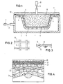
- Fig. 1 shows the shape of a molding machine, consisting of a lower part 1 and one Upper part 7 with an intermediate seal 10 on the edge.
- the lower part 1 is with a Provide wire mesh layer 5.
- the hollow mold is subjected to negative pressure through a line 2 while opening a valve 3.
- the negative pressure is generated by pumping out the air.
- compressed air flows in through a line 8 by opening a valve 9.
- Beads 6 are introduced with the air.
- the beads have a diameter of 3mm and are made of PP.
- the air pressure is 6 bar.
- the compressed air flows through the fabric layer 5.
- the fabric layer 5 optimally absorbs the compressed air and directs it to openings 4 in the lower part 1.
- the fabric layer 5 is two-layer and made of wire mesh. Each layer has a different mesh size.
- the bead-side fabric layer has a much smaller mesh size than the bottom-side fabric layer. In the exemplary embodiment 100 mesh (0.14 mm). Depending on the wire diameter and the mesh size, this results in a wire diameter of 0.112 mm. In exceptional cases, the wire diameter can be chosen freely.
- Fig. 2 shows the bead-side fabric layer in an enlarged plan view. The steel wires are on top of each other.
- Fig. 3 shows the cross section through the bead-side wire mesh. In the base, the wires 11 and 12 form arcs 13, so that a flat surface (apart from the contour of the fabric layer shown in FIG. 1) is created on the bead side.
- the multilayer of the fabric is shown in Fig. 4.
- the layer 20 consists of the wires 11 and 12 shown in FIGS. 2 and 3.
- the layer 22 is identical to the layer 20.
- the layer 23 shows the clear features of a support fabric.
- the wire diameter is a multiple of the wire diameter of the layers 20 to 22, as is the mesh size resulting from the distance between the wires.
- the layer 24 contains an even coarser support fabric. All fabric layers are sintered together.
- the contour shown in Fig. 1 is created by deformation in a suitable press.
- the die belonging to the press has the contour of the lower part 1 on the hollow side.
- the fabric shown in FIG. 4 lies on the die.
- a layer of non-foamed PE film is placed over it, the thickness of which corresponds to the fabric thickness.
- the associated male part has approximately the shape of the molded part shown in FIG. 1 or Mold cavity. Roughly means that the layer of foil placed on it must also be taken into account when forming the patrix.
- the beads expand due to the heating. Due to the plasticized outer surface of the Beads and due to the pressure it occurs at all points of contact between the beads to a weld. At the same time, the gusset spaces between the beads close.
- the finished product 6 is after cooling sufficiently after opening the mold from the Mold cavity removed.
Landscapes
- Engineering & Computer Science (AREA)
- Mechanical Engineering (AREA)
- Moulds For Moulding Plastics Or The Like (AREA)
- Laminated Bodies (AREA)
- Molding Of Porous Articles (AREA)
- Treatment Of Fiber Materials (AREA)
- Casting Or Compression Moulding Of Plastics Or The Like (AREA)
Abstract
Description
Grundsätzlich wird bei der Beadsherstellung zwischen der Herstellung im Autoklaven und der Extrusionsherstellung unterschieden. Nach der Herstellung werden die Beads in Silos oder anderer geeigneter Weise bevorratet, bevor eine Anwendung stattfindet.
Die Beads werden in einer Form, dem sogenannten Formteilautomaten zusammengefügt. Das geschieht durch Erwärmung der Beads an den Oberflächen bis zu einer mehr oder weniger intensiven Plastifizierung und durch Zusammendrücken. Bei ausreichendem Aufschmelzen der Oberfläche und Druck verschweißen die Beads miteinander. Bei weniger starkem Aufschmelzen und Druck entsteht gegebenenfalls eine noch ausreichende Verklebung/Versinterung.
Die EP 0664313 zeigt ein gattungsgemäßes Verfahren, mit dem Abbildungen der Öffnungen vermieden werden. Dabei wird an mindestens einer Formwand innen ein Drahtgewebe oder ein gelochtes Blech angelegt, deren Dicke 0,2 bis 5, vorzugsweise 0,5 bis 2, mm beträgt Als Material für Draht bzw. Blech soll Metall, wie Aluminium oder rostfreier Stahl, aber auch temperaturbeständiger Kunststoff dienen. Drahtgewebe bzw. Lochblech sollen lose in das Formwerkzeug eingelegt, eingepreßt, durch Clipse oder Schrauben befestigt oder punktförmig eingelöstet oder geschweißt werden. Die Formwände können wie üblich gleichmäßig mit Perforierungen versehen sein, so daß der Heißdampf das Forminnere gleichmäßig besprühen kann. Da durch die Einlagen ein gewisser Abstand zwischen Formteiloberfläche und Forminnenwand hergestellt wird, können sich die Düsen nicht an der Formteiloberfläche abbilden. Dafür aber drücken sich die an der Oberfläche sitzenden Partikel teilweise in die Löcher des Gewebes bzw. Bleches ein, so daß deren Struktur sich der Formteiloberfläche einprägt. Im Ergebnis wird der Oberfläche anstelle ungleichmäßiger Abbildungen eine ganz gleichmäßige Strukturierung gegeben.
Die strukturierten Oberflächen sind nicht immer von Vorteil. Z.B. sind in der Lebensmittelindustrie glatte, leicht reinigungsfähige Flächen aus Hygienegründen gefordert. Das können die aus der EP 0664313 bekannten Formteile und Fomteilautomaten nicht leisten.
Überraschenderweise entstehen bereits ansprechend glatte Oberflächen, wenn die Maschenweite der schaumseitigen Gewebelage kleiner als der halbe Durchmesser der eingesetzten Beads ist.
In der Anwendung auf Formteile für Lebensmittelbereiche oder dergleichen Anwendungen mit ähnlichem oder noch höherem Hygienestandard sind für die schaumseitige Gewebelage kleinere Maschenweiten vorgesehen z.B. 0,001 bis 0,5 mm, vorzugsweise 0,005 bis 0,2 mm bei Beads mit einem Durchmesser von 3 bis 5 mm. Bei anderen Beads lassen sich gleichartige(zugehörige) Grenzen mit einigen Versuchen festlegen.
Das Wasser wirkt im Form als Trennmittel zwischen den Beads.
Kondensat, das sich auf der Strecke des Heißdampfes von der schaumseitigen Gewebelage zum Austrag aus dem Formteilautomaten bildet, wird wahlweise nach Beendigung der Heißdampfbeaufschlagung unter Anlegung eines Unterdruckes abgesogen.
In der Regel ist ausreichend, in der Abdampfstrecke (Weg des austretenden Heißdampfes) eine Dampfkammer einzurichten und dort den Unterdruck anzulegen.
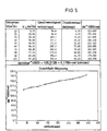
einem Probendurchmesser von 100 mm und
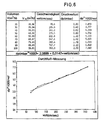
einem Probendurchmesser von 100 mm durchgeführt worden. Das erfindungsgemäß verwendete Gewebe nach Fig. 5 besitzt insgesamt 4 Gewebelagen mit einer schaumseitigen Gewebelage mit einer Maschenweite von 0,005 mm.
Das erfindungsgemäß verwendete Gewebe nach Fig. 6 besitzt gleichfalls 4 Gewebelagen mit einer schaumseitigen Gewebelage mit einer Maschenweite von 0,14 mm.
Grundsätzliche Kühlvorteile ergeben sich durch eine wesentliche geringere Masse des erfindungsgemäß verwendeten Gewebes gegenüber vergleichbaren Systemen.
Außerdem läßt sich z.B. auf ganz kurzem Wege mittels eingeblasener Kühlluft eine Abkühlung des erfindungsgemäß verwendeten Gewebes und der außen liegenden Schichten des entstandenen Formteiles erreichen. Die außen liegenden Schichten des entstandenen Formteiles bestimmen dessen Abmessungen.
Der Herstellungszyklus endet mit dem Ausstoß der entstandenen Formteile aus dem Formteilautomaten. Die formbestimmenden Flächen sollen dann eine Temperatur unterhalb des Glaspunktes haben. Bei Polystyrol liegt die Ausstoßtemperatur bei 40 bis 90 Grad Celsius, bei PP bei 70 bis 100 Grad Celsius.
Vorteilhafterweise ist die erfindungsgemäße glatte Gewebefläche auch dem Ausformen günstig.
und/oder
Die Webrichtung bleibt auch dann erhalten, wenn die von einer Gewebebahn für das erfindungsgemäß verwendete Gewebe Abschnitte abgelängt oder Ausschnitte gefertigt werden. Die Webrichtung läßt sich an den Schuß- und Kettfäden bzw. Schuß- und Kettdrähten identifizieren. Dabei ist die Unterscheidung leicht, weil Schuß und Kette im Gewebe sich erkennbar unterscheiden. Zur erfindungsgemäßen Verlegung um 90 Grad versetzt muß lediglich darauf geachtet werden, daß sich in zwei benachbarten, erfindungsgemäß verwendeten Gewebelagen die gleichartig verarbeiteten Fasern bzw. Drähte sich einander kreuzen. Bei 90-Grad-Versatzlage entsteht ein genau senkrechtes Kreuzen.
Es kann aber auch Kreuzen unter einem Winkel stattfinden.
Metallische erfindungsgemäß verwendete Gewebelagen lassen sich auch versintern. Das Versintern ähnelt dem Verschweißen. Unter Erwärmung der Berührungsflächen findet ein Zusammendrücken statt. Während die Erwärmung beim Verschweißen deutlich höher als beim Versintern ist, ist der Druck beim Verschweißen wesentlich geringer als beim Versintern.
Ferner kommt ein Verlöten der metallischen, erfindungsgemäß verwendete Gewebelagen in Betracht.
Jegliche erfindungsgemäß verwendeten Gewebelagen lassen sich verkleben oder mit Befestigungs- oder Spannelementen in der gewünschten Form und Position halten. Als Befestigungs- oder Spannelemente eignen sich diverse Mittel, z.B. Schrauben oder Nieten. Nichtmetallische erfindungsgemäß verwendete Gewebelagen können z.B. aus Kohlefasern bestehen. Kohlefasern besitzen eine hohe Festigkeit und eine geringe Wärmeleitfähigkeit. Es kann von Vorteil sein, metallische erfindungsgemäß verwendete Gewebelagen mit nichtmetallischen erfindungsgemäß verwendeten Gewebelagen zu kombinieren.
Insbesondere metallische, erfindungsgemäß verwendete Gewebelagen eignen sich auch für eine Befestigung durch Verpressen oder Verbördeln.
Zwar ist eine teilflächige Verbindung der erfindungsgemäß verwendeten Gewebelagen und/oder teilflächige Verbindung des erfindungsgemäß verwendeten Gewebes mit den dahinter liegenden Formteilautomatenwänden möglich, eine vollflächige Verbindung kann aber Vorteile bringen.
Die Erfindung verbessert auch die Zykluszeiten. Diese können verkürzt werden. Bei 100 mm dicken Formteilen können ohne weiteres Zykluszeiten von 2 bis 5 min eingehalten werden
Die Verformung metallischer, erfindungsgemäß verwendeter Gewebe kann mittels einer geeigneten Presse durch Pressen und/oder Tiefdrücken erreicht werden. Die Presse besitzt Matrize und Stempel, die der gewünschten Formfläche nachgebildet sind.
Die Verformung kann kalt erfolgen, wird aber wesentlich erleichtert, wenn die erfindungsgemäß verwendeten metallischen Gewebe erwärmt werden.
Bei gemeinsamer Verformung ist es von Vorteil, auf der schaumseitigen Lage ein Biegehilfsmaterial mit etwa der gleichen Dicke wie das erfindungsgemäß verwendeten Gewebe zu befestigen, so daß die schaumseitige Lage in dem verformten Verbundmaterial aus Gewebe und Biegehilfsmaterial in etwa die neutrale Faser bildet. Dabei wird die Erkenntnis genutzt, daß die neutrale Faser bei einer Biegeverformung die geringste Verformung erfährt. In etwa die gleiche Dicke schließt Abweichungen der Biegehilfsmaterial-Dicke von plus/minus 50% von der Gewebe-Dicke ein. Das Biegehilfsmaterial ist vorzugsweise eine ungeschäumte Folie/Platte aus PE(Polyethylen) und/oder PP(Polypropylen).
Das PE/PP-Material bildet zugleich eine Schutzfolie. Es ist von Vorteil an allen belasteten Gewebe-Außenflächen während der Verformung Schutzfolien anzuordnen.
Zur Schonung der Gewebe-Außenflächen trägt auch eine höhere Werkzeughärte an den Berührungsflächen mit dem erfindungsgemäß verwendeten Gewebe bei. Das verhindert ein Verkrallen des erfindungsgemäß verwendeten Gewebes in der Werkzeugberührungsfläche.
Vorteilhafterweise ist die erfindungsgemäße Technik zur Verlängerung der Reisezeit für Formteilautomaten auch unabhängig von der Mehrlagigkeit des Gewebes und auch auf andere Formteilautomaten anwendbar.
Durch Querbedampfen wird die Qualität der Verschweißung der Beads vergleichmäßigt. Bei dem Bedampfen in nur einer Richtung fällt die Dampftemperatur während des Materialdurchganges durch Wärmeabgabe ab. Folglich fällt entsteht hinsichtlich der Oberflächentemperatur der Beads auch ein Gefälle. Durch Querbedampfen werden die Bereiche mit Frischdampf erreicht, die vorher am Ende der Dampfstrecke lagen.
Die Querbedampfung wird dadurch erreicht, daß an weiteren Formteilautomatenwänden Bedampfungsöffnungen und ggfs. Abdampföffnungen mit entsprechenden Zuleitungen und Ableitungen vorgesehen sind. Zur Steuerung der einzelnen Leitungen sind in den Zuleitungen und/oder Ableitungen geeignete Schieber vorgesehen.
Zugleich fließt Druckluft durch Öffnen eines Ventils 9 durch eine Leitung 8 nach. Mit der Luft werden Beads 6 eingetragen. Die Beads haben einen Durchmesser von 3mm und bestehen aus PP. Der Luftdruck beträgt 6 bar.
Die Gewebeschicht 5 ist zweischichtig und aus Drahtgewebe. Jede Schicht hat eine unterschiedliche Maschenweite. Die beadsseitige Gewebeschicht hat eine wesentlich geringere Maschenweite als die unterteilseitige Gewebeschicht. Im Ausführungsbeispiel 100 mesh (0,14 mm). Dabei ergibt sich in üblicher Abhängigkeit der Drahtdurchmesser von der Maschenweite ein Drahtdurchmesser von 0,112 mm. In Ausnahmefällen wird der Drahtdurchmesser frei gewählt.
Die Fig. 2 zeigt die beadsseitige Gewebeschicht in einer vergrößerten Draufsicht. Die Stahldrähte liegen übereinander. Fig. 3 zeigt den Querschnitt durch das beadsseitige Drahtgewebe. In der Unterlage bilden die Drähte 11 und 12 Bögen 13, so daß beadsseitig eine ebene (abgesehen von der in Fig. 1 gezeigten Kontur der Gewebeschicht) Fläche entsteht.
Dazwischen befindet sich im Ausführungsbeispiel eine Filterlage 21 aus ungewebten, nebeneinander liegenden Drähten.
Die Lage 23 zeigt die deutlichen Merkmale eines Stützgewebes. Der Drahtdurchmesser ist ein Vielfaches vom Drahtdurchmesser der Lagen 20 bis 22, desgleichen die sich aus dem Abstand der Drähte ergebende Maschenweite.
Die Lage 24 beinhaltet ein noch gröberes Stützgewebe.
Alle Gewebelagen sind miteinander versintert.
Formhohlraumes. In etwa heißt, es muß bei der Konturbildung der Patrize noch die aufgelegte Folienschicht berücksichtigt werden.
Claims (33)
- Verfahren zum Betrieb eines Formteilautomaten zur Herstellung von Kunststoffschaumprodukten aus Beads, mit einem Fomhohlraum, in den die Beads eingetragen und mit einem gasförmigen Wärmeträger, insbesondere Heißdampf, beaufschlagt werden, wobei der gasförmige Wärmeträger aus einer Formteilautomatenfläche in den Formhohlraum eintritt und durch eine andere Formteilautomatenfläche wieder austritt und wobei an mindestens einer Formteilautomatenfläche ein Gewebe vorgesehen ist, gekennzeichnet durch Verwendung eines mehrlagigen Gewebes (5) mit einer schaumseitigen feinmaschigen Gewebelage (11,12,20,21,22) und einer darunter angeordneten grobmaschigen Gewebelage (23,24) als Stützkonstruktion.
- Verfahren nach Anspruch 1, gekennzeichnet durch Herstellung glatter Formteilflächen
- Verfahren nach Anspruch 1 oder 2, gekennzeichnet durch die Verwendung einer schaumseitigen Gewebelage (11,12,20,21,22) mit einer Maschenweite, die kleiner als der halbe Beadsdurchmesser ist und/oder oder durch die Verwendung einer Gewebekonstruktion mit zumindest einer schaumseitig massearmen Gewebelage und/oder einer Kondensatabführung.
- Verfahren nach Anspruch 3, gekennzeichnet durch eine Kondensatabsaugung.
- Verfahren nach Anspruch 3, gekennzeichnet durch Verwendung einer Dampfkammer in der Abdampfstrecke und Anlegung eines Unterdruckes an die Dampfkammer.
- Verfahren nach Anspruch 3, gekennzeichnet durch die Verwendung einer Gewebelage (11,12,20,21,22) mit einer Maschenweite von 0,001 bis 0,5 mm, vorzugsweise 0,005 bis 0,2 mm, bei Beads mit einem Durchmesser von 3 bis 5 mm.
- Verfahren nach Anspruch 4, gekennzeichnet durch die Herstellung reinigungsfreundlicher Flächen für den Transport und/oder Lagerung von Lebensmitteln und/oder für die Verarbeitung von Formteilen unter Aufkaschieren von dünnen Folien.
- Verfahren nach Anspruch 2 oder 3, gekennzeichnet durch Verwendung von Geweben (11,12,20,21,22, 23,24) mit einer sich aus der Maschenweite ergebenden üblichen Fadenoder Drahtdicke oder einer Dicke, die gleich oder kleiner der 10fachen, vorzugsweise gleich oder kleiner der fünffachen Maschenweite ist oder sogar gleich oder kleiner als die Maschenweite ist.
- Verfahren nach einem der Ansprüche 1 bis 8, gekennzeichnet durch die Beaufschlagung des Formteiles durch das Gewebe hindurch mit Kühlmittel nach der Beendigung der Bedampfung.
- Verfahren nach Anspruch 9, gekennzeichnet durch die Verwendung von Kühlluft und/oder Kühlwasser als Kühlmittel.
- Verfahren nach einem der Ansprüche nach einem der Ansprüche 1 bis 10, gekennzeichnet durch eine Querbedampfung.
- Verfahren nach Anspruch 11, gekennzeichnet durch Dampfzuführungsöffnungen und/oder Abdämpföffnungen in den verschiedenen Formteilautomatenwänden und Zuleitungen bzw. Ableitungen mit Schiebern.
- Verfahren nach einem der Ansprüche 1 bis 12, gekennzeichnet durch Umkehrung der Freiblasen der Gewebelage.
- Verfahren nach Anspruch 13, gekennzeichnet durch Freiblasen nach einem Zyklus oder mehreren Zyklen unabhängig von der Verschmutzungslage oder Freiblasen nach der Verschmutzung.
- Verfahren nach Anspruch 13 oder 14, gekennzeichnet durch Umkehrung der Dampfströmung mit und/oder ohne Befüllung des Formteilautomaten.
- Verfahren nach einem der Ansprüche 1 bis 15, gekennzeichnet durch die Verwendung einer Stützgebekonstruktion (23,24) mit einer Maschenweite, die gegenüber der Maschenweite der schaumseitigen Gewebekonstruktion das 1,5 bis 20 fache beträgt, und mit einer Faden- und oder Drahtdicke, die gegenüber der schaumseitigen Gewebekonstruktion (11,12,20,21,22) das 1,5 bis 20fache beträgt.
- Verfahren nach Anspruch 16, gekennzeichnet durch die Verwendung einer Stützgewebekonstruktion (23,24), deren Maschenweite mindestens gleich der Maschenweite der schaumseitigen Gewebekonstruktion (11,12,20,21,22) plus dem 2,5fachen der Faden- oder Drahtdicke der schaumseitigen Gewebekonstruktion (11,12,20,21,22) ist.
- Verfahren nach einem der Ansprüche 1 bis 17, gekennzeichnet durch Verwendung einer Gewebekonstruktion (20,21,22,23,24) mit einer Versatzlage (21) zwischen den Gewebelagen.
- Verfahren nach einem der Ansprüche 1 bis 18, gekennzeichnet durch die Verwendung von Gewebekonstruktionen (5), deren Gewebelagen (11,12,20,21,22,23,24) untereinander und/oder mit der zugehörigen Formteilautomatenwand ganz oder teilweise verbunden sind, durcha) Verschweißen und/oderb) Verkleben und/oderc) Versintern und/oderd) Befestigungselement und/odere) Verpressen und/oder Verbördeln
- Verfahren nach Anspruch 19, gekennzeichnet durch induktive Verschweißung.
- Verfahren nach einem der Ansprüche 1 bis 19, gekennzeichnet durch Drähte aus Stahl und/oder Fäden aus Kohlefasern.
- Verfahren nach einem oder mehreren der Ansprüche 1 bis 21, gekennzeichnet durch die Verwendung von Gewebekonstruktionen (5) mit einer Dicke bis 15 mm.
- Verfahren nach Anspruch 22, gekennzeichnet durch Verwendung einer Gewebekonstruktion (5) mit einer Dicke von 3 bis 5 mm.
- Verfahren nach einem der Ansprüche nach einem der Ansprüche 1 bis 23, gekennzeichnet durch einzelne oder gruppenweise oder gemeinsame Verformung aller Gewebelagen (11,12,20,21,22,23,24) zur Anpassung an die Formteilautomatenwände.
- Verfahren nach Anspruch 24, gekennzeichnet durch die Pressen der Gewebelagen (11,12,21,22,23,24).
- Verfahren nach Anspruch 25, gekennzeichnet durch Verwendung einer Schutzfolie und/oder Schutzplatte zwischen Gewebelage (11,12,21,22,23,24) und Preßwerkzeug und/oder Verwendung zumindest oberflächengehärteter Presswerkzeuge.
- Verfahren nach Anspruch 25, gekennzeichnet durch Verwendung einer Schutzfolie an der schaumseitigen Gewebelage (11,12,20,21,22) mit einer Dicke, die etwa die Dicke des übrigen zur Verformung bestimmten Materiales hat.
- Verfahren nach Anspruch 26 oder 27, gekennzeichnet durch die Verwendung Schutzfolien und/oder Platten aus PE und/oder PP.
- Verfahren nach einem der Ansprüche 24 bis 28, gekennzeichnet durch eine Wärmebehandlung metallischer Gewebelagen vor der Verformung und/oder nach der Verbindung der Gewebelagen.
- Verfahren nach einem der Ansprüche 1 bis 29, gekennzeichnet durch Verwendung einer oder mehrerer Filterlagen (22) an dem Gewebe und/oder durch Verwendung von Geweben mit einer oder mehreren eingeschlossenen Filterlagen (22).
- Verfahren nach einem oder mehreren der Ansprüche 1 bis 30 gekennzeichnet durch Verwendung einstückiger oder mehrstückiger Auskleidungen von Formteilhohlräumen und/oder ganz oder teilweise selbsttragender Auskleidungen.
- Verfahren nach einem oder mehreren der Ansprüche 1 bis 31, gekennzeichnet durch die Verwendung von porösen, gas- und/oder wasserdurchlässigen Formteilautomatenwänden
- Verfahren nach Anspruch 32 gekennzeichnet durch die Verwendung von Formteilwänden aus Aluminium und/oder Sintermaterial.
Applications Claiming Priority (3)
| Application Number | Priority Date | Filing Date | Title |
|---|---|---|---|
| DE19907279A DE19907279A1 (de) | 1999-02-21 | 1999-02-21 | Formteilautomat zur Herstellung von Kunststoffschaumprodukten aus Beads |
| DE19907279 | 1999-02-21 | ||
| PCT/EP2000/001392 WO2000048813A1 (de) | 1999-02-21 | 2000-02-21 | Formteilautomat zur herstellung von kunststoffschaumprodukten aus beads |
Publications (2)
| Publication Number | Publication Date |
|---|---|
| EP1154888A1 EP1154888A1 (de) | 2001-11-21 |
| EP1154888B1 true EP1154888B1 (de) | 2002-09-04 |
Family
ID=7898246
Family Applications (1)
| Application Number | Title | Priority Date | Filing Date |
|---|---|---|---|
| EP00910683A Expired - Lifetime EP1154888B1 (de) | 1999-02-21 | 2000-02-21 | Verfahren zum betrieb eines formteilautomaten zur herstellung von kunststoffschaumprodukten aus beads |
Country Status (12)
| Country | Link |
|---|---|
| US (1) | US6620357B2 (de) |
| EP (1) | EP1154888B1 (de) |
| JP (1) | JP2003529458A (de) |
| KR (1) | KR100780098B1 (de) |
| CN (1) | CN1150083C (de) |
| AU (1) | AU760368B2 (de) |
| CA (1) | CA2359104A1 (de) |
| CZ (1) | CZ20012986A3 (de) |
| DE (2) | DE19907279A1 (de) |
| MX (1) | MXPA01008172A (de) |
| PL (1) | PL193166B1 (de) |
| WO (1) | WO2000048813A1 (de) |
Cited By (1)
| Publication number | Priority date | Publication date | Assignee | Title |
|---|---|---|---|---|
| KR101883829B1 (ko) | 2016-06-28 | 2018-08-01 | 유영수 | 발포성형물 금형 장치 및 금형 장치를 이용한 발포성형물 제조방법 |
Families Citing this family (41)
| Publication number | Priority date | Publication date | Assignee | Title |
|---|---|---|---|---|
| DE10016671A1 (de) * | 2000-04-04 | 2001-10-11 | Gefinex Polymerschaeume Gmbh | Kunststoffschaumprodukte aus Beads |
| DE10120906A1 (de) * | 2001-01-04 | 2002-07-18 | Fagerdala Deutschland Gmbh | Oberflächengestaltung von Sichtteilen |
| DE10335721A1 (de) * | 2003-08-05 | 2005-03-10 | Clion Ireland Ltd | Formung thermoplastisch gebundener luftdurchlässiger Bauteile |
| US20050167871A1 (en) * | 2004-01-29 | 2005-08-04 | Sunil Kesavan | Gas-permeable molds for composite material fabrication and molding method |
| US7201625B2 (en) * | 2004-03-11 | 2007-04-10 | Tzong In Yeh | Foam product having outer skin and method for producing the same |
| DE102006031435A1 (de) | 2005-08-23 | 2008-01-10 | Airbus Deutschland Gmbh | Pressvorrichtung zur energieeffizienten Aushärtung eines Sandwichbauteils für Luftfahrzeuge |
| DE102005039837B4 (de) * | 2005-08-23 | 2010-12-09 | Airbus Deutschland Gmbh | Verfahren zur Herstellung von Sandwichbauteilen |
| US7338396B2 (en) * | 2005-09-08 | 2008-03-04 | Rawlings Sporting Goods Company, Inc. | Preformed lacrosse pocket and packaging for same |
| US7670202B2 (en) * | 2005-11-14 | 2010-03-02 | Tzong In Yeh | Foam product |
| CN101676098B (zh) * | 2005-11-28 | 2012-06-27 | 叶宗殷 | 发泡产品 |
| CN100579769C (zh) * | 2005-11-28 | 2010-01-13 | 叶宗殷 | 制造具有表皮的发泡产品的方法 |
| BRPI0621374B1 (pt) * | 2006-03-13 | 2017-12-26 | Daisen Industry Co., Ltd. | Method for manufacturing foamed molded part |
| US20140197563A1 (en) * | 2010-12-15 | 2014-07-17 | Robert Niven | Carbon dioxide sequestration in concrete articles |
| KR101396903B1 (ko) * | 2012-03-16 | 2014-05-19 | 지피에스코리아(주) | 표면질감 표현이 가능한 발포수지성형장치 |
| US8845940B2 (en) | 2012-10-25 | 2014-09-30 | Carboncure Technologies Inc. | Carbon dioxide treatment of concrete upstream from product mold |
| WO2014121198A1 (en) | 2013-02-04 | 2014-08-07 | Coldcrete, Inc. | System and method of applying carbon dioxide during the production of concrete |
| US9643343B2 (en) * | 2013-03-11 | 2017-05-09 | Sonoco Development, Inc. | Method for molding recycled EPS using powder adhesive and steam |
| US9376345B2 (en) | 2013-06-25 | 2016-06-28 | Carboncure Technologies Inc. | Methods for delivery of carbon dioxide to a flowable concrete mix |
| US20160107939A1 (en) | 2014-04-09 | 2016-04-21 | Carboncure Technologies Inc. | Methods and compositions for concrete production |
| US9388072B2 (en) | 2013-06-25 | 2016-07-12 | Carboncure Technologies Inc. | Methods and compositions for concrete production |
| US10927042B2 (en) | 2013-06-25 | 2021-02-23 | Carboncure Technologies, Inc. | Methods and compositions for concrete production |
| CN103600454B (zh) * | 2013-12-03 | 2017-01-25 | 顺达(芜湖)汽车饰件有限公司 | 方向盘发泡装置 |
| WO2015123769A1 (en) | 2014-02-18 | 2015-08-27 | Carboncure Technologies, Inc. | Carbonation of cement mixes |
| WO2015154174A1 (en) | 2014-04-07 | 2015-10-15 | Carboncure Technologies, Inc. | Integrated carbon dioxide capture |
| JP6297916B2 (ja) * | 2014-05-12 | 2018-03-20 | 株式会社ジェイエスピー | 発泡粒子成形体の製造方法 |
| CN104633435B (zh) * | 2015-01-12 | 2017-02-22 | 龚智勇 | 超轻超强封闭式气体充填式发泡瓶板及其制备方法 |
| US10189964B2 (en) * | 2015-06-08 | 2019-01-29 | Covestro Llc | Methods for preparing open-celled polyurethane foams, systems for use therein, and open-celled polyurethane foams produced thereby |
| US20170066110A1 (en) * | 2015-09-08 | 2017-03-09 | Baker Hughes Incorporated | Polycrystalline diamond, methods of forming same, cutting elements, and earth-boring tools |
| AU2017249444B2 (en) | 2016-04-11 | 2022-08-18 | Carboncure Technologies Inc. | Methods and compositions for treatment of concrete wash water |
| SG11201912759RA (en) | 2017-06-20 | 2020-01-30 | Carboncure Tech Inc | Methods and compositions for treatment of concrete wash water |
| CN107127925A (zh) * | 2017-07-14 | 2017-09-05 | 苏州恒昇海绵机械制造有限公司 | 一种海绵成型发泡模具 |
| TWI680851B (zh) * | 2017-11-23 | 2020-01-01 | 三弘實業有限公司 | 囊袋之製造方法及其模具 |
| JP2020026078A (ja) * | 2018-08-10 | 2020-02-20 | 株式会社ミマキエンジニアリング | 転写方法 |
| US10889027B2 (en) * | 2019-03-12 | 2021-01-12 | JS Greenlife Technology Co., LTD. | Shaping mold for forming a porous starch container |
| CA3138622A1 (en) | 2019-04-26 | 2020-10-29 | Carboncure Technologies Inc. | Carbonation of concrete aggregates |
| IT202000000175A1 (it) * | 2020-01-08 | 2021-07-08 | Persico Spa | Processo di stampaggio e relativa macchina di stampaggio |
| CN111012165B (zh) * | 2020-01-13 | 2021-06-01 | 南京溧水高新产业股权投资有限公司 | 一种气体循环式防烫蒸汽加热机 |
| US12521908B2 (en) | 2020-06-12 | 2026-01-13 | Carboncure Technologies Inc. | Methods and compositions for delivery of carbon dioxide |
| DE102021109197A1 (de) | 2021-04-13 | 2022-10-13 | Feurer Febra Gmbh | Werkzeug zur Herstellung von Schaumstoffteilen |
| KR20230124275A (ko) * | 2022-02-18 | 2023-08-25 | 한화솔루션 주식회사 | 발포용 몰드 장치 및 이를 이용한 물리 발포 공정 |
| CN115179498B (zh) * | 2022-06-20 | 2023-09-29 | 佛山市顺德区天玛仕电子有限公司 | 一种环保节能的塑料件注塑模具 |
Family Cites Families (16)
| Publication number | Priority date | Publication date | Assignee | Title |
|---|---|---|---|---|
| US3419648A (en) * | 1965-08-18 | 1968-12-31 | Dow Chemical Co | Method of molding polystyrene |
| US4264544A (en) * | 1973-10-02 | 1981-04-28 | The Unisource Corporation | Method of molding a rigid integral skin foamed resin product in a mold having a vented lid |
| US4430286A (en) * | 1980-07-14 | 1984-02-07 | Celotex Corporation | Variable density board having improved thermal and acoustical properties and method and apparatus for producing same |
| JPS608047A (ja) * | 1983-06-28 | 1985-01-16 | Japan Styrene Paper Co Ltd | 予備発泡粒子型内成型体の製造方法 |
| JPS61116527A (ja) * | 1984-11-13 | 1986-06-04 | Toyoda Gosei Co Ltd | 表皮付発泡ビーズ成形品の製造方法 |
| US4681724A (en) * | 1986-04-28 | 1987-07-21 | United Technologies Corporation | Removable irreversibly shrinking male mandrel |
| DE8617619U1 (de) * | 1986-07-02 | 1987-01-15 | Vorwerk & Co Interholding Gmbh, 5600 Wuppertal | Gehäusebauteil aus laminiertem Mehrlagengewebe |
| US5242637A (en) * | 1989-07-12 | 1993-09-07 | Teijin Limited | Process for the production of composite molded articles |
| DE69017620T2 (de) * | 1989-12-21 | 1995-09-21 | Jsp Corp | Pressform und ihre Verwendung in einem Verfahren zum Herstellen von formgeschäumten Artikeln. |
| US5792398A (en) * | 1991-06-12 | 1998-08-11 | Glasis Holding Ab | Hot pressing method of forming a composite laminate containing expanded thermoplastic particles |
| CA2170512A1 (en) * | 1993-09-21 | 1995-03-30 | Gordon L. Mcgregor | Puffed insulative material and methods for making such material |
| ES2131212T3 (es) * | 1993-09-24 | 1999-07-16 | Dynamit Nobel Kunststoff Gmbh | Procedimiento para producir articulos de espuma de particulas de polipropileno expandido (ppe). |
| DE4401579A1 (de) * | 1994-01-20 | 1995-07-27 | Basf Ag | Schaumstoff-Formteile mit strukturierter Oberfl{che |
| JP3596926B2 (ja) * | 1994-09-19 | 2004-12-02 | 株式会社カネカ | 型内発泡成形用金型表面材及びそれを用いた金型 |
| JPH1142717A (ja) * | 1997-07-28 | 1999-02-16 | Kansei Corp | 車両用内装部材の製造方法 |
| FR2772300A1 (fr) * | 1997-12-12 | 1999-06-18 | Reydel Sa | Procede de fabrication, par moulage, d'une piece en materiau expanse |
-
1999
- 1999-02-21 DE DE19907279A patent/DE19907279A1/de not_active Ceased
-
2000
- 2000-02-21 CN CNB008040060A patent/CN1150083C/zh not_active Expired - Lifetime
- 2000-02-21 JP JP2000599578A patent/JP2003529458A/ja active Pending
- 2000-02-21 MX MXPA01008172A patent/MXPA01008172A/es active IP Right Grant
- 2000-02-21 KR KR1020017010312A patent/KR100780098B1/ko not_active Expired - Fee Related
- 2000-02-21 CZ CZ20012986A patent/CZ20012986A3/cs unknown
- 2000-02-21 CA CA002359104A patent/CA2359104A1/en not_active Abandoned
- 2000-02-21 DE DE50000450T patent/DE50000450D1/de not_active Expired - Lifetime
- 2000-02-21 PL PL350585A patent/PL193166B1/pl unknown
- 2000-02-21 WO PCT/EP2000/001392 patent/WO2000048813A1/de not_active Ceased
- 2000-02-21 AU AU32809/00A patent/AU760368B2/en not_active Ceased
- 2000-02-21 EP EP00910683A patent/EP1154888B1/de not_active Expired - Lifetime
-
2001
- 2001-08-20 US US09/933,257 patent/US6620357B2/en not_active Expired - Fee Related
Cited By (1)
| Publication number | Priority date | Publication date | Assignee | Title |
|---|---|---|---|---|
| KR101883829B1 (ko) | 2016-06-28 | 2018-08-01 | 유영수 | 발포성형물 금형 장치 및 금형 장치를 이용한 발포성형물 제조방법 |
Also Published As
| Publication number | Publication date |
|---|---|
| MXPA01008172A (es) | 2002-10-23 |
| PL350585A1 (en) | 2003-01-13 |
| AU3280900A (en) | 2000-09-04 |
| PL193166B1 (pl) | 2007-01-31 |
| KR20010102133A (ko) | 2001-11-15 |
| DE19907279A1 (de) | 2000-08-31 |
| CN1348406A (zh) | 2002-05-08 |
| US6620357B2 (en) | 2003-09-16 |
| CA2359104A1 (en) | 2000-08-24 |
| AU760368B2 (en) | 2003-05-15 |
| US20020047225A1 (en) | 2002-04-25 |
| EP1154888A1 (de) | 2001-11-21 |
| DE50000450D1 (de) | 2002-10-10 |
| KR100780098B1 (ko) | 2007-11-29 |
| JP2003529458A (ja) | 2003-10-07 |
| WO2000048813A1 (de) | 2000-08-24 |
| CN1150083C (zh) | 2004-05-19 |
| CZ20012986A3 (cs) | 2002-02-13 |
Similar Documents
| Publication | Publication Date | Title |
|---|---|---|
| EP1154888A1 (de) | Formteilautomat zur herstellung von kunststoffschaumprodukten aus beads | |
| DE102016209044B4 (de) | Sohlenform zum Herstellen einer Sohle und Anordnung einer Vielzahl von Sohlenformen | |
| EP2714974B1 (de) | Mehrlagengewebe, seine verwendung sowie verfahren zur herstellung von compositen | |
| DE3445656C2 (de) | ||
| EP3086916B1 (de) | Vorrichtung und verfahren zur herstellung eines partikelschaumstoffteils | |
| DE68927578T2 (de) | Verfahren und Vorrichtung zum Blasformen | |
| WO2003043795A1 (de) | Formwerkzeug zur herstellung von partikelschaumformteilen | |
| DE102007063261A1 (de) | Verfahren zur kontinuierlichen Herstellung von bahn- oder plattenförmigen Belägen sowie Anlage hierzu | |
| EP0465610B1 (de) | Gaskissen, verfahren und vorrichtung zu seiner herstellung | |
| DE10007911A1 (de) | Formteilautomat mit neuer Auskleidung für Kunststoffschaumprodukte aus Beads | |
| DE4311592C2 (de) | Verfahren und Vorrichtung zum Herstellen von Kunststoff enthaltenden Teilen mit wenigstens einer Hohlkammer und entsprechend hergestelltes Teil | |
| DE10116508B4 (de) | Verfahren zum Herstellen eines geformten Harzlaminats | |
| DE10231567A1 (de) | Verfahren zur Herstellung eines Formteilwerkzeuges, darauf hergestelltes Werkzeug und Partikelschaumformteil mit entsprechender Oberflächenstruktur | |
| DE10016671A1 (de) | Kunststoffschaumprodukte aus Beads | |
| EP0683030A2 (de) | Tiefgezogenes Formteil, Tiefziehverfahren und Tiefziehvorrichtung zur Herstellung des Formteils | |
| DE102008050210B4 (de) | Verfahren zum Verformen von thermoplastischen Wabenkörpern | |
| DE69225503T2 (de) | Vorrichtung zum formen und verbinden von sitzen | |
| EP3216581A1 (de) | Flächengebilde und verfahren zur herstellung eines flächengebildes in sandwich-leichtbau-ausführung | |
| DE19648093A1 (de) | Verfahren zur Herstellung strangförmiger Körper aus Kunststoffschaum-Beads | |
| DE2622777B2 (de) | Verfahren und Vorrichtung zum kontinuierlichen Herstellen von Schichtmaterial mit Schaumstoffteilchen | |
| DE29924253U1 (de) | Formteilautomat zur Herstellung von Kunststoffschaumprodukten aus Beads | |
| EP1645399B1 (de) | Verfahren und Vorrichtung zum Herstellen von Kunststoff enthaltenden Produkten | |
| DE102021109197A1 (de) | Werkzeug zur Herstellung von Schaumstoffteilen | |
| CH642903A5 (de) | Verfahren zum herstellen von formkoerpern aus geschaeumtem kunststoff, wie z.b. geschaeumtem polystyrol. | |
| DE10157427A1 (de) | Formteilautomat |
Legal Events
| Date | Code | Title | Description |
|---|---|---|---|
| PUAI | Public reference made under article 153(3) epc to a published international application that has entered the european phase |
Free format text: ORIGINAL CODE: 0009012 |
|
| 17P | Request for examination filed |
Effective date: 20010713 |
|
| AK | Designated contracting states |
Kind code of ref document: A1 Designated state(s): AT BE CH CY DE DK ES FI FR GB GR IE IT LI LU MC NL PT SE |
|
| GRAG | Despatch of communication of intention to grant |
Free format text: ORIGINAL CODE: EPIDOS AGRA |
|
| GRAG | Despatch of communication of intention to grant |
Free format text: ORIGINAL CODE: EPIDOS AGRA |
|
| GRAH | Despatch of communication of intention to grant a patent |
Free format text: ORIGINAL CODE: EPIDOS IGRA |
|
| RTI1 | Title (correction) |
Free format text: METHOD OF OPERATION OF A MOULDED-PART MACHINE FOR PRODUCING PLASTIC FOAM PRODUCTS FROM BEADS |
|
| RTI1 | Title (correction) |
Free format text: METHOD OF OPERATION OF A MOULDED-PART MACHINE FOR PRODUCING PLASTIC FOAM PRODUCTS FROM BEADS |
|
| 17Q | First examination report despatched |
Effective date: 20011210 |
|
| GRAH | Despatch of communication of intention to grant a patent |
Free format text: ORIGINAL CODE: EPIDOS IGRA |
|
| RAP1 | Party data changed (applicant data changed or rights of an application transferred) |
Owner name: GEFINEX POLYMERSCHAEUME GMBH |
|
| GRAA | (expected) grant |
Free format text: ORIGINAL CODE: 0009210 |
|
| AK | Designated contracting states |
Kind code of ref document: B1 Designated state(s): DE ES FR GB SE |
|
| REG | Reference to a national code |
Ref country code: GB Ref legal event code: FG4D Free format text: NOT ENGLISH |
|
| REG | Reference to a national code |
Ref country code: IE Ref legal event code: FG4D Free format text: GERMAN |
|
| REF | Corresponds to: |
Ref document number: 50000450 Country of ref document: DE Date of ref document: 20021010 |
|
| PG25 | Lapsed in a contracting state [announced via postgrant information from national office to epo] |
Ref country code: SE Free format text: LAPSE BECAUSE OF FAILURE TO SUBMIT A TRANSLATION OF THE DESCRIPTION OR TO PAY THE FEE WITHIN THE PRESCRIBED TIME-LIMIT Effective date: 20021204 |
|
| GBT | Gb: translation of ep patent filed (gb section 77(6)(a)/1977) |
Effective date: 20021227 |
|
| ET | Fr: translation filed | ||
| PG25 | Lapsed in a contracting state [announced via postgrant information from national office to epo] |
Ref country code: ES Free format text: LAPSE BECAUSE OF FAILURE TO SUBMIT A TRANSLATION OF THE DESCRIPTION OR TO PAY THE FEE WITHIN THE PRESCRIBED TIME-LIMIT Effective date: 20030328 |
|
| PLBE | No opposition filed within time limit |
Free format text: ORIGINAL CODE: 0009261 |
|
| STAA | Information on the status of an ep patent application or granted ep patent |
Free format text: STATUS: NO OPPOSITION FILED WITHIN TIME LIMIT |
|
| REG | Reference to a national code |
Ref country code: IE Ref legal event code: FD4D Ref document number: 1154888E Country of ref document: IE |
|
| 26N | No opposition filed |
Effective date: 20030605 |
|
| REG | Reference to a national code |
Ref country code: DE Ref legal event code: R081 Ref document number: 50000450 Country of ref document: DE Owner name: SSW PEARLFOAM GMBH, DE Free format text: FORMER OWNER: GEFINEX POLYMERSCHAEUME GMBH, 99885 OHRDRUF, DE Effective date: 20140410 Ref country code: DE Ref legal event code: R081 Ref document number: 50000450 Country of ref document: DE Owner name: IZOBLOK GMBH, DE Free format text: FORMER OWNER: GEFINEX POLYMERSCHAEUME GMBH, 99885 OHRDRUF, DE Effective date: 20140410 |
|
| REG | Reference to a national code |
Ref country code: FR Ref legal event code: CD Owner name: SSW PEARLFOAM GMBH, DE Effective date: 20141119 |
|
| REG | Reference to a national code |
Ref country code: FR Ref legal event code: TP Owner name: SSW PEARLFOAM GMBH, DE Effective date: 20141203 |
|
| REG | Reference to a national code |
Ref country code: FR Ref legal event code: PLFP Year of fee payment: 16 |
|
| REG | Reference to a national code |
Ref country code: FR Ref legal event code: PLFP Year of fee payment: 17 |
|
| REG | Reference to a national code |
Ref country code: GB Ref legal event code: 732E Free format text: REGISTERED BETWEEN 20160512 AND 20160518 |
|
| REG | Reference to a national code |
Ref country code: FR Ref legal event code: PLFP Year of fee payment: 18 |
|
| REG | Reference to a national code |
Ref country code: DE Ref legal event code: R081 Ref document number: 50000450 Country of ref document: DE Owner name: IZOBLOK GMBH, DE Free format text: FORMER OWNER: SSW PEARLFOAM GMBH, 99885 OHRDRUF, DE |
|
| REG | Reference to a national code |
Ref country code: FR Ref legal event code: PLFP Year of fee payment: 19 |
|
| REG | Reference to a national code |
Ref country code: FR Ref legal event code: CD Owner name: IZOBLOK GMBH, DE Effective date: 20180827 |
|
| PGFP | Annual fee paid to national office [announced via postgrant information from national office to epo] |
Ref country code: GB Payment date: 20181205 Year of fee payment: 20 |
|
| PGFP | Annual fee paid to national office [announced via postgrant information from national office to epo] |
Ref country code: DE Payment date: 20190109 Year of fee payment: 20 |
|
| PGFP | Annual fee paid to national office [announced via postgrant information from national office to epo] |
Ref country code: FR Payment date: 20190228 Year of fee payment: 20 |
|
| REG | Reference to a national code |
Ref country code: DE Ref legal event code: R071 Ref document number: 50000450 Country of ref document: DE |
|
| REG | Reference to a national code |
Ref country code: GB Ref legal event code: PE20 Expiry date: 20200220 |
|
| PG25 | Lapsed in a contracting state [announced via postgrant information from national office to epo] |
Ref country code: GB Free format text: LAPSE BECAUSE OF EXPIRATION OF PROTECTION Effective date: 20200220 |