EP1149748B1 - Bremsanlage für ein Kraftfahrzeug - Google Patents
Bremsanlage für ein Kraftfahrzeug Download PDFInfo
- Publication number
- EP1149748B1 EP1149748B1 EP01119230A EP01119230A EP1149748B1 EP 1149748 B1 EP1149748 B1 EP 1149748B1 EP 01119230 A EP01119230 A EP 01119230A EP 01119230 A EP01119230 A EP 01119230A EP 1149748 B1 EP1149748 B1 EP 1149748B1
- Authority
- EP
- European Patent Office
- Prior art keywords
- brake
- input rod
- brake operating
- pressure
- brake pedal
- Prior art date
- Legal status (The legal status is an assumption and is not a legal conclusion. Google has not performed a legal analysis and makes no representation as to the accuracy of the status listed.)
- Expired - Lifetime
Links
Images


Classifications
-
- B—PERFORMING OPERATIONS; TRANSPORTING
- B60—VEHICLES IN GENERAL
- B60T—VEHICLE BRAKE CONTROL SYSTEMS OR PARTS THEREOF; BRAKE CONTROL SYSTEMS OR PARTS THEREOF, IN GENERAL; ARRANGEMENT OF BRAKING ELEMENTS ON VEHICLES IN GENERAL; PORTABLE DEVICES FOR PREVENTING UNWANTED MOVEMENT OF VEHICLES; VEHICLE MODIFICATIONS TO FACILITATE COOLING OF BRAKES
- B60T8/00—Arrangements for adjusting wheel-braking force to meet varying vehicular or ground-surface conditions, e.g. limiting or varying distribution of braking force
- B60T8/32—Arrangements for adjusting wheel-braking force to meet varying vehicular or ground-surface conditions, e.g. limiting or varying distribution of braking force responsive to a speed condition, e.g. acceleration or deceleration
- B60T8/34—Arrangements for adjusting wheel-braking force to meet varying vehicular or ground-surface conditions, e.g. limiting or varying distribution of braking force responsive to a speed condition, e.g. acceleration or deceleration having a fluid pressure regulator responsive to a speed condition
- B60T8/44—Arrangements for adjusting wheel-braking force to meet varying vehicular or ground-surface conditions, e.g. limiting or varying distribution of braking force responsive to a speed condition, e.g. acceleration or deceleration having a fluid pressure regulator responsive to a speed condition co-operating with a power-assist booster means associated with a master cylinder for controlling the release and reapplication of brake pressure through an interaction with the power assist device, i.e. open systems
- B60T8/441—Arrangements for adjusting wheel-braking force to meet varying vehicular or ground-surface conditions, e.g. limiting or varying distribution of braking force responsive to a speed condition, e.g. acceleration or deceleration having a fluid pressure regulator responsive to a speed condition co-operating with a power-assist booster means associated with a master cylinder for controlling the release and reapplication of brake pressure through an interaction with the power assist device, i.e. open systems using hydraulic boosters
- B60T8/442—Arrangements for adjusting wheel-braking force to meet varying vehicular or ground-surface conditions, e.g. limiting or varying distribution of braking force responsive to a speed condition, e.g. acceleration or deceleration having a fluid pressure regulator responsive to a speed condition co-operating with a power-assist booster means associated with a master cylinder for controlling the release and reapplication of brake pressure through an interaction with the power assist device, i.e. open systems using hydraulic boosters the booster being a fluid return pump, e.g. in combination with a brake pedal force booster
-
- B—PERFORMING OPERATIONS; TRANSPORTING
- B60—VEHICLES IN GENERAL
- B60T—VEHICLE BRAKE CONTROL SYSTEMS OR PARTS THEREOF; BRAKE CONTROL SYSTEMS OR PARTS THEREOF, IN GENERAL; ARRANGEMENT OF BRAKING ELEMENTS ON VEHICLES IN GENERAL; PORTABLE DEVICES FOR PREVENTING UNWANTED MOVEMENT OF VEHICLES; VEHICLE MODIFICATIONS TO FACILITATE COOLING OF BRAKES
- B60T13/00—Transmitting braking action from initiating means to ultimate brake actuator with power assistance or drive; Brake systems incorporating such transmitting means, e.g. air-pressure brake systems
- B60T13/10—Transmitting braking action from initiating means to ultimate brake actuator with power assistance or drive; Brake systems incorporating such transmitting means, e.g. air-pressure brake systems with fluid assistance, drive, or release
- B60T13/66—Electrical control in fluid-pressure brake systems
- B60T13/68—Electrical control in fluid-pressure brake systems by electrically-controlled valves
- B60T13/686—Electrical control in fluid-pressure brake systems by electrically-controlled valves in hydraulic systems or parts thereof
-
- B—PERFORMING OPERATIONS; TRANSPORTING
- B60—VEHICLES IN GENERAL
- B60T—VEHICLE BRAKE CONTROL SYSTEMS OR PARTS THEREOF; BRAKE CONTROL SYSTEMS OR PARTS THEREOF, IN GENERAL; ARRANGEMENT OF BRAKING ELEMENTS ON VEHICLES IN GENERAL; PORTABLE DEVICES FOR PREVENTING UNWANTED MOVEMENT OF VEHICLES; VEHICLE MODIFICATIONS TO FACILITATE COOLING OF BRAKES
- B60T13/00—Transmitting braking action from initiating means to ultimate brake actuator with power assistance or drive; Brake systems incorporating such transmitting means, e.g. air-pressure brake systems
- B60T13/10—Transmitting braking action from initiating means to ultimate brake actuator with power assistance or drive; Brake systems incorporating such transmitting means, e.g. air-pressure brake systems with fluid assistance, drive, or release
- B60T13/66—Electrical control in fluid-pressure brake systems
- B60T13/72—Electrical control in fluid-pressure brake systems in vacuum systems or vacuum booster units
-
- B—PERFORMING OPERATIONS; TRANSPORTING
- B60—VEHICLES IN GENERAL
- B60T—VEHICLE BRAKE CONTROL SYSTEMS OR PARTS THEREOF; BRAKE CONTROL SYSTEMS OR PARTS THEREOF, IN GENERAL; ARRANGEMENT OF BRAKING ELEMENTS ON VEHICLES IN GENERAL; PORTABLE DEVICES FOR PREVENTING UNWANTED MOVEMENT OF VEHICLES; VEHICLE MODIFICATIONS TO FACILITATE COOLING OF BRAKES
- B60T17/00—Component parts, details, or accessories of power brake systems not covered by groups B60T8/00, B60T13/00 or B60T15/00, or presenting other characteristic features
- B60T17/18—Safety devices; Monitoring
- B60T17/22—Devices for monitoring or checking brake systems; Signal devices
- B60T17/221—Procedure or apparatus for checking or keeping in a correct functioning condition of brake systems
-
- B—PERFORMING OPERATIONS; TRANSPORTING
- B60—VEHICLES IN GENERAL
- B60T—VEHICLE BRAKE CONTROL SYSTEMS OR PARTS THEREOF; BRAKE CONTROL SYSTEMS OR PARTS THEREOF, IN GENERAL; ARRANGEMENT OF BRAKING ELEMENTS ON VEHICLES IN GENERAL; PORTABLE DEVICES FOR PREVENTING UNWANTED MOVEMENT OF VEHICLES; VEHICLE MODIFICATIONS TO FACILITATE COOLING OF BRAKES
- B60T7/00—Brake-action initiating means
- B60T7/02—Brake-action initiating means for personal initiation
- B60T7/04—Brake-action initiating means for personal initiation foot actuated
- B60T7/042—Brake-action initiating means for personal initiation foot actuated by electrical means, e.g. using travel or force sensors
-
- B—PERFORMING OPERATIONS; TRANSPORTING
- B60—VEHICLES IN GENERAL
- B60T—VEHICLE BRAKE CONTROL SYSTEMS OR PARTS THEREOF; BRAKE CONTROL SYSTEMS OR PARTS THEREOF, IN GENERAL; ARRANGEMENT OF BRAKING ELEMENTS ON VEHICLES IN GENERAL; PORTABLE DEVICES FOR PREVENTING UNWANTED MOVEMENT OF VEHICLES; VEHICLE MODIFICATIONS TO FACILITATE COOLING OF BRAKES
- B60T8/00—Arrangements for adjusting wheel-braking force to meet varying vehicular or ground-surface conditions, e.g. limiting or varying distribution of braking force
- B60T8/32—Arrangements for adjusting wheel-braking force to meet varying vehicular or ground-surface conditions, e.g. limiting or varying distribution of braking force responsive to a speed condition, e.g. acceleration or deceleration
- B60T8/88—Arrangements for adjusting wheel-braking force to meet varying vehicular or ground-surface conditions, e.g. limiting or varying distribution of braking force responsive to a speed condition, e.g. acceleration or deceleration with failure responsive means, i.e. means for detecting and indicating faulty operation of the speed responsive control means
- B60T8/92—Arrangements for adjusting wheel-braking force to meet varying vehicular or ground-surface conditions, e.g. limiting or varying distribution of braking force responsive to a speed condition, e.g. acceleration or deceleration with failure responsive means, i.e. means for detecting and indicating faulty operation of the speed responsive control means automatically taking corrective action
- B60T8/94—Arrangements for adjusting wheel-braking force to meet varying vehicular or ground-surface conditions, e.g. limiting or varying distribution of braking force responsive to a speed condition, e.g. acceleration or deceleration with failure responsive means, i.e. means for detecting and indicating faulty operation of the speed responsive control means automatically taking corrective action on a fluid pressure regulator
Definitions
- JP-A-4-56669 discloses an example of a known technique for diagnosing a vacuum booster of a vehicle braking system, for any abnormality.
- This known diagnosing technique is based on a fact that the vacuum booster becomes inoperative to perform a normal boosting function when a negative pressure of a negative pressure source to which the vacuum booster is connected has been raised above a predetermined upper limit.
- a pressure switch is used to either mechanically or electrically detect that the negative pressure of the negative pressure source has exceeded the upper limit.
- US 4,978,177 which is considered closest prior art, shows a force sensitive resistor placed between a brake rod connected with a brake master cylinder of a vehicle and a brake lever connected to a brake pedal. As soon as the pedal is depressed and a small clearance is eliminated, the resistor is pressed against its bearings and creates a signal corresponding to the brake operating force.
- WO96/28329A discloses a construction of an input rod made of two parts, in which a pressure transducer is located between the two parts of the input rod to measure a force transmitted between the two parts of the input rod.
- WO95/03966A shows a brake system determining not the braking force, but instead determining the distance travelled by an actuator submitted to the braking force.
- US5350225A suggests to detect either a relative movement between a brake pedal and the input rod or a brake operating force using force sensors, similarly to US 4,978,177 .
- EP0754607A discloses to detect a brake operating force in order to increase a braking force in case a brake supporting force should not show a predetermined ratio to the brake operating force.
- a braking system for an automotive vehicle comprising: a brake operating member; a booster for boosting a brake operating force acting on the brake operating member, the booster including an input rod which receives the brake operating force; a master cylinder for producing a hydraulic pressure on the basis of an input force received from the booster ; a wheel brake cylinder which is activated by the hydraulic pressure produced by the master cylinder, to brake a wheel of the automatic vehicle; a connecting mechanism connecting the brake operating member and the input rod to each other, so as to permit a relative movement between the brake operating member and the input rod in an axial direction of the input rod by a predetermined distance; and a signal generating device generating an output signal relating to the brake operating force depending upon a distance of the relative movement.
- the relative movement of the brake operating member and the input rod of the booster is directly or indirectly utilized by the signal generating device.
- the connecting mechanism includes (a) a connecting member connecting the brake operating member and the input rod to each other, so as to permit the relative movement between the brake operating member and the input rod in the axial direction of the input rod by the predermined maximum distance; (b) a pivotal member connected to the brake operating member such that the pivotal member is pivotal about an axis perpendicular to the axial direction of the input rod, on the basis of the relative movement between the brake operating member and the input rod; and (c) an elastic member for biasing the brake operating member and the input rod away from each other in the axial direction.
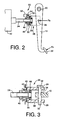
- a braking system helpful for understanding the present invention includes a brake operating member in the form of a brake pedal 10, and a vacuum booster 12 (hereinafter referred to simply as "booster 12") through which the brake pedal 10 is operatively connected to a master cylinder 12.
- the booster 12 has a negative-pressure chamber and a variable-pressure chamber.
- the negative-pressure chamber is connected to a negative air pressure source, which is a negative-pressure portion of an engine of an automotive vehicle.
- the variable-pressure chamber is selectively communicated with the negative-pressure chamber and the atmosphere.
- the booster 12 includes a power piston which is axially moved by a difference between the pressures in the negative-pressure and variable-pressure chambers.
- the master cylinder 14 is a tandem type hydraulic cylinder including a housing, and two pressurizing pistons which are slidably received in the housing, in series with each other.
- the pressurizing pistons cooperate with the housing to define two mutually independent pressurizing chambers in front of the respective pressurizing chambers.
- the master cylinder 14 is arranged to mechanically produce substantially equal hydraulic pressures in the two pressurizing chambers, depending upon the brake operating force F P acting on the brake pedal 10.
- This structure does not form part of but is helpful for understanding the invention.
- the brake pedal 10 is connected at its fixed end portion thereof to the vehicle body via a pin 20, such that the brake pedal 10 is pivotable about the axis of the pin 20.
- the brake pedal 10 has a pedal pad 22 fixed at its free end, so that the brake operating force F P is applied to the pedal pad 22 when the brake pedal 10 is depressed at the pedal pad 22 by the vehicle operator.
- the brake pedal 10 is connected at a longitudinally intermediate portion thereof to an input rod 24 of the booster 12.
- the input rod 24 projects from the housing of the booster 12 toward the brake pedal 10, and is connected,at its end portion remote from the housing, to the brake pedal 10 through a clevis 26.
- the clevis 26 is a generally U-shaped structure consisting of a pair of side plates 28, 28 which are spaced apart from each other in a direction perpendicular to the axis of the input rod 24, and a base plate 30 connecting the two side plates 28, 28 at their corresponding ends.
- the two side plates 28, 28 have respective first pin holes 32, 32 which are concentric with each other in the above-indicated direction.
- the brake pedal 10 has a second pin hole 34 formed through its longitudinally intermediate portion.
- a pin 36 extends through the first pin holes 32, 32 and the second pin hole 34, whereby the clevis 26 is connected to the brake pedal 10 such that the clevis 26 and the brake pedal 10 are pivotable relative to each other about the axis of the pin 36.
- the first pin holes 32, 32 and the second pin hole 34 are all round holes having a diameter slightly larger than the diameter of the pin 36, so that a relative movement of the brake pedal 10 and the clevis 26 in the axial direction of the input rod 24 is substantially prevented.
- the base plate 30 is connected to the end portion of the input rod 24 through a connecting member 40.
- the connecting member 40 is fixed to the input rod 24, and includes a first stop 42, a second stop 44, and an engaging portion located between the first and second stops 42, 44.
- the engaging portion slidably engages an opening formed through the base plate 30, so that the connecting member 40 is axially movable relative to the base plate 30 of the clevis 26, over a maximum distance determined by abutting contacts of the first and second stops 42, 44 with the base plate 30.
- the first stop 42 is brought into abutting contact with the base plate 30 when the clevis 26 and the input rod 24 are moved toward each other, while the second stop 44 is brought into abutting contact with the base plate 30 when the clevis 36 and the input rod 24 are moved away from each other.
- a compression coil spring 46 is disposed between the base plate 30 and the connecting member 40, so that the base plate 30 and the connecting member 40 are normally biased in opposite axial directions away from each other, under a predetermined biasing force of the spring 46. Accordingly, the second stop 44 is normally held in abutting contact with the base 30.
- the connecting member 40 carries a brake operating force switch 50 attached thereto.
- the switch 50 includes a housing 42, and a movable member 54 extending from the housing 52 toward the brake pedal 10.
- the switch 50 is attached to the connecting member 40 such that the axis or centerline of the movable member 54 is parallel to the axis of the connecting member 40, and such that the movable member 54 is engageable at its free end with a bracket 56 fixed to the base plate 30.
- the switch 50 is arranged and positioned so that the switch 50 is in an OFF state when the second stop 44 is in contact with the base plate 30 as shown in Fig.
- the brake operating force F P can be transmitted from the clevis 26 to the input rod 24 through the connecting member 40, more precisely, through the abutting contact of the base plate 30 with the first stop 42, only after the base plate 30 is brought into contact with the first stop 42. Since the force F P is transmitted from the clevis 26 to the input rod 24 through the first stop 42, the switch 50 is protected against exposure to an excessively large force during operation of the brake pedal 10.
- the present braking system has two sub-systems, one of which includes two hydraulically operated brakes 58 for front wheels FL, FR shown in Fig.1 , and the other of which includes two hydraulically operated brakes for rear wheels (not shown).
- the two brakes 58 include respective front wheel brake cylinders 60 for braking the respectively front left and right wheels FL, FR.
- These front wheel brake cylinders 60 are connected to one of the two pressurizing chambers of the master cylinder 14.
- the brakes for the rear wheels include respective rear wheel brake cylinders (not shown) which are connected to the other pressurizing chamber of the master cylinder 14. Since the front and rear sub-systems are substantially identical in construction with each other, only the front sub-system for the front wheels FL, FR will be described by reference to Fig. 1 , by way of example.
- the master cylinder 14 is connected through a main fluid passage 64 to the wheel brake cylinders 60 for the front left and rear wheels FL, FR.
- the main fluid passage 64 consists of a common passage 66 extending from the master cylinder 14, and two branch passages 68 extending from the end of the common passage 66 which is remote from the master cylinder 14.
- a fluid flow control valve in the form of a normally open solenoid-operated two-position valve 70 is connected to the common passage 66.
- This valve 70 includes a solenoid coil which produces a magnetic force for selectively placing the valve 70 in an open position and a closed position.
- the branch passages 68 are connected, at their ends remote from the common passage 66, to the respective wheel brake cylinders 60.
- a pump passage 72 is connected to a portion of the main fluid passage 64 between the two-position valve 70 and the wheel brake cylinders 60.
- a pump 74 is connected to the pump passage 72.
- a check valve in the form of a by-pass valve 94 is provided so as to by-pass the two-position valve 70.
- This by-pass valve 94 is provided to permit a flow of a working fluid in a direction from the master cylinder 14 toward the wheel brake cylinders 60, even if the two-position valve 70 is closed due to a fluid force acting on a movable member of the valve 70, or is mechanically locked in its closed position, during an operation of the brake pedal 10.
- a pressure relief valve in the form of a pressure difference generator valve 96 is also provided so as to by-pass the two-position valve 70.
- This pressure difference generator valve 96 is opened when the delivery pressure of the pump 74 is going to be higher than the pressure in the master cylinder 14 by more than a predetermined amount of pressure difference, so as to permit a flow of the working fluid from the pump 74 toward the master cylinder 14.
- the pressure difference generator valve 96 functions to maintain the difference between the pressure in the wheel brake cylinders 60 and the master cylinder 14 within a predetermined range, while the two-position valve 70 is in the closed position.
- a pressure holding valve 100 which is a normally open solenoid-operated shut-off valve.
- the pressure holding valve 100 is placed in its closed position when its solenoid coil is energized. In the closed position, the valve 100 inhibits a flow of the working fluid from the pump 74 toward the wheel brake cylinder 60, for thereby holding the pressure in the wheel brake cylinder 60 at the present level.
- a check valve in the form of a by-pass valve 104 is provided so as to by-pass each pressure holding valve 100. This by-pass valve 104 functions to permit a high rate of flow of the fluid from the wheel brake cylinder 60 back to the master cylinder 14 when the brake pedal 10 is released.
- a reservoir passage 106 is connected at its one end to a portion of each branch passage 68 between the pressure holding valve 100 and the wheel brake cylinder 60, and at the other end to a reservoir 108.
- a pressure reducing valve 110 which is a normally closed solenoid-operated shut-off valve.
- the pressure reducing valve 110 is placed in its open position when its solenoid coil is energized. In the open position, the valve 110 permits a flow of the working fluid from the wheel brake cylinder 60 toward the reservoir 108, for thereby reducing the pressure in the wheel brake cylinder 60.
- the reservoir 108 includes a housing, and a reservoir piston 112 substantially fluid-tightly and slidably received within the housing.
- the reservoir piston 112 cooperates with the housing to define a reservoir chamber 114, and is biased by a spring 116 so that the working fluid is stored in the reservoir chamber 114 under pressure.
- the reservoir chamber 114 is connected through the pump passage 72 to the main fluid passage 64.
- the pump passage 72 is divided by the pump 74 into a suction passage 120 and a delivery passage 122.
- a suction valve 124 and a delivery valve 126 which are both check valves, are provided in the respective suction and delivery passages 120, 122.
- a damper 128 and an orifice 129 are provided in the delivery passage 122, in series connection with each other, for the purpose of reducing pressure pulsation of the fluid delivered from the pump 74.
- a fluid supply passage 130 is connected at its one end to a portion of the suction passage 120 between the suction valve 124 and the reservoir 108, and at the other end to a portion of the main fluid passage 64 between the master cylinder 14 and the two-position valve 70.
- An inflow control valve 132 which is a normally closed solenoid-operated shut-off valve, is provided in the fluid supply passage 130.
- the inflow control valve 132 is controlled by an electronic control unit 200 (which will be described), such that the valve 132 is placed in the closed position when the pump 74 is required to pump up the fluid from the reservoir 108 while the pumping of the fluid supplied from the master cylinder 14 should be avoided, and such that the valve 132 is opened when the pump 74 is required to pump up the fluid from the master cylinder 14.
- a check valve 134 is provided in a portion of the suction passage 120 between the reservoir 108 and a point of connection of the suction passage 120 and the fluid supply passage 130.
- This check valve 134 functions to inhibit a flow of the fluid from the master cylinder 14 toward the reservoir 108 while the inflow control valve 132 is in the open position.
- the check valve 134 permits the pressurized fluid from the master cylinder 14 to be supplied to the pump 74, without a drop of the fluid pressure.
- the reservoir passage 106 is connected to a portion of the suction passage 120 between the check valve 134 and the reservoir 108.
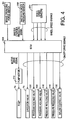
- a software arrangement of the braking system will be described by reference to the block diagram of Fig. 4 , which shows only the sub-system for braking the front wheels FL, FR, by way of example.
- the present braking system includes the electronic control unit (abbreviated as "ECU” in Fig. 4 ) 200, which is principally constituted by a computer incorporating a central processing unit (CPU), a read-only memory (ROM) and a random-access memory (RAM).
- the electronic control unit 200 is adapted to execute a braking effect characteristic control routine and an anti-lock braking pressure control routine, according to control programs stored in the ROM , while utilizing a temporary data storage function of the RAM.
- the term "braking effect characteristic control” is interpreted to mean controlling the pressures in the wheel brake cylinders 60, so as to restrain reduction of a braking effect provided by the wheel brake cylinders 60, which reduction may result from some abnormality or malfunction of the booster 12.
- anti-lock braking pressure control is interpreted to mean controlling the pressure in the wheel brake cylinder 50 for each wheel, so as to prevent an excessive locking tendency of the wheel during an operation of the brake pedal 10.
- the working fluid is recirculated through the braking circuit, by operation of the pump 74 while the braking system is operated in an anti-lock braking pressure control mode, namely, while the anti-lock braking pressure control routine is executed.
- the braking system is adapted to effect the braking effect characteristic control by utilizing the pump 74 during an operation of the brake pedal 10.
- the present embodiment utilizes the pump 74 for not only the braking effect characteristic control, but also the anti-lock braking pressure control.
- the master cylinder pressure sensor 202 is provided to detect the pressure in the master cylinder 14 or in any other portion of the braking system at which the pressure is substantially equal to the pressure in the master cylinder 14.
- the wheel speed sensors 204 are provided for detecting the rotating speeds of the respective four wheels of the automotive vehicle. Each sensor 204 generates an output signal indicative of the rotating speed of the corresponding wheel.
- an electric motor 210 for driving the pump 74.
- the driver circuit of the pump motor 210 receives a motor drive signal from the electronic control unit 200.
- To the output side of the electronic control unit 200 there are also connected the solenoid coils of the two-position valve 70, pressure holding valves 100, pressure reducing valves 110 and inflow control valve 132. The solenoid coils are energized according to ON/OFF drive signals received from the electronic control unit 200.
- the braking effect characteristic control routine is illustrated in the flow chart of Fig. 5 . Before explaining this routine by reference to the flow chart, the concept of the routine will be first described briefly.
- the graph in Fig. 6 indicates a normal relationship and an abnormal relationship between the brake operating force F P and the pressure P M in the master cylinder 14, when the booster is in a normal state and in an abnormal state, respectively.
- the booster 12 is not at all capable of boosting the brake operating force F P when the booster 12 is in the abnormal state.
- the master cylinder pressure P M corresponding to a given value of the brake operating force F P is higher when the booster 12 is in the normal state than when it is in the abnormal state.
- the master cylinder pressure P M corresponding to a predetermined value F PS of the brake operating force F P is a normal value P MS .
- the brake operating force switch 50 is adapted to detect a moment when the brake operating force F P has become equal to the predetermined value F PS , so as to determine that the booster 12 is abnormal if the master cylinder pressure P M is lower than a predetermined lower limit P MK when the brake operating force F P is equal to the predetermined value F PS .
- the lower limit P MK is lower than the normal value P MS .
- the set load F SET does not coincide with a value obtained according to the above equation, since the brake pedal 10 is biased by a return spring (not shown) toward its non-operated position. That is, the set load F SET is obtained by subtracting an appropriate value attributed to the return spring, from a value obtained according to the above equation.
- the predetermined value F PS is determined such that the brake operating force F P necessarily exceeds this value F PS during an ordinary operation of the brake pedal 10 when the booster 12 is normally functioning. Described in detail, the predetermined value F PS is determined to be smaller than a value of the brake operating force F P at which an increase in the master cylinder pressure P M is initiated during an increase in the brake operating force F P , when the brake operating force F P is transmitted to the master cylinder 12, without any boosting of the brake operating force F P due to any abnormality of the booster 12. In this specific example, the predetermined value F PS is determined to be 5kgf.
- the present example is further adapted such that upon detection that the booster 12 is abnormal, the two-position valve 70 is closed, and the pump 74 is operated to assure that the pressure P B in the wheel brake cylinders 60 is higher than the master cylinder pressure P M by a fixed pressure difference ⁇ P AB , as shown in the graph of Fig. 7 .
- the fixed pressure difference ⁇ P AB is determined by the pressure difference generator valve 96.
- the present example is adapted to at least restrict or reduce the amount of reduction in the braking effect due to abnormality of the booster 12.
- the pump 74 is activated to increase the pressure P B in the wheel brake cylinders 60, immediately after the abnormality of the booster 12 is detected, as indicated in Fig. 7 .
- the fixed pressure difference ⁇ P AB is determined not to be larger than the normal value P MS of the master cylinder pressure P M which is taken when the brake operating force F P is equal to the predetermined value F PS where the booster 12 is in the normal state.
- an increase of the wheel brake cylinder pressure P B by the pump 74 may be initiated a suitable time after the detection that the booster 12 is abnormal, for instance, when the master cylinder pressure P M has been increased to a predetermined value which is higher than the atmospheric pressure.
- the fixed pressure difference ⁇ P AB may be determined according to various design concepts. For instance, the fixed pressure difference ⁇ P AB may be determined so that the master cylinder 14 generates a minimum pressure P M required to brake the wheels, when the brake operating force F P is within a nominal value (within a range of 40-60kgf, for example) where the booster 12 is abnormal, completely failing to perform a boosting function.
- the braking effect characteristic control routine will be described in detail by reference to the flow chart of Fig. 5 .
- step S1 to check the brake operating force switch 50 and the master cylinder pressure sensor 202 for any abnormality such as electrical disconnection or short-circuiting. This checking is effected while the brake pedal 10 is in the non-operated position.
- step S2 to determine whether any abnormality of the switch 50 or sensor 202 was detected in step S1. If an affirmative decision (YES) is obtained in step S2, the present routine is terminated, and the routine is not initiated until the ignition switch is turned on again after it is turned off. Thus, an operation to increase the wheel brake cylinder pressure P B by the pump 74 in step S7 is inhibited as long as the switch 50 and/or the sensor 202 is/are abnormal.
- step S2 If a negative decision (NO) is obtained in step S2, the control flow goes to step S3 to determine whether the brake operating force switch 50 has been turned ON, more specifically, has been turned from the OFF state to the ON state. That is, step S3 is provided to determine whether the brake operating force F P has increased to the predetermined value F PS . If the switch 50 is in the OFF state, a negative decision (NO) is obtained in step S3, and one cycle of execution of the present routine is terminated. If the switch 50 has been turned ON in a subsequent cycle of execution of the routine, the control flow goes to step S4 to detect the master cylinder pressure P M on the basis of the output signal (analog signal) of the master cylinder pressure sensor 202. The level of this analog output signal continuously changes with a continous change in the master cylinder pressure P M .
- step S5 the control flow goes to step S5 to determine whether the detected master cylinder pressure P M is lower than the predetermined lower limit P MK' that is, to determine whether the booster 12 is in the abnormal state. If the detected master cylinder pressure P M is equal to or higher than the lower limit P MK' that is, if a negative decision (NO) is obtained in step S5, one cycle of execution of the present routine is terminated. If the master cylinder pressure P M is lower than the lower limit P MK' that is, if an affirmative decision (YES) is obtained in step S5, the control flow goes to step S6 to determine that the booster 12 is in the abnormal state, and activate a suitable alarm indicator to inform the vehicle operator that the booster 12 is abnormal.
- Step S6 is followed by step S7 in which the pump 74 is activated to increase the pressure P B in the wheel brake cylinders 60, more specifically, to close the two-position valve 70, open the inflow control valve 132, and activate the pump 74.
- the pressure P B in the wheel brake cylinders 60 is raised such that the wheel brake cylinder pressure P B is higher than the master cylinder pressure P M by the fixed pressure difference ⁇ P AB .
- the control flow goes to step S8 to determine whether the brake operating force switch 50 has been turned OFF, that is, to determine whether the pump 74 should be turned off. If a negative decision (NO) is obtained in step S8, the control flow goes to step S7.
- Steps S7 and S8 are repeatedly implemented until an affirmative decision (YES) is obtained in step S8, that is, until the switch 50 has been turned OFF.
- the control flow goes to step S9 to terminate the operation to increase the wheel brake cylinder pressure P B by the pump 74, more specifically, to open the two-position valve 70, close the inflow control valve 132 and turn off the pump 74.
- YES affirmative decision
- the anti-lock brake pressure control routine is initiated for any one of the wheels, during an operation of the brake pedal 10, when an excessive locking tendency of that wheel is detected.
- Thins routine is formulated to control the pressure P B in the locking wheel, by selectively establishing one of a pressure increasing state, a pressure holding state and a pressure reducing state, so as to eliminate the excessive locking tendency of the wheel, while monitoring the rotating speed of the wheel in question on the basis of the output signal of the corresponding wheel speed sensor 204, and the vehicle running speed.
- the pressure increasing state is established by opening the pressure holding valve 100 and closing the pressure reducing valve 110.
- the pressure holding state is established by closing both of the pressure holding and reducing valves 100, 110.
- the pressure reducing state is established by closing the pressure holding valve 100 and opening the pressure reducing valve 110.
- the pump motor 210 is activated, and the working fluid is returned by the pump 74 from the reservoir 108 to the main fluid passage 64.
- the brake operating force F P is considered to be an input to the booster 12
- the master cylinder pressure P M is considered to be an output from the booster 12
- the brake operating force switch 50, the master cylinder pressure switch 202 and a portion of the electronic control unit 200 assigned to implement steps S3-S6 of the routine of Fig. 5 cooperate with each other to provide a booster diagnosing device.
- the brake pedal 10 is connected to the clevis 26 by engagement of a pin 250 with an elongate hole 252, as shown in Fig. 8 , so as to permit a relative movement of the brake pedal 10 and the clevis 26 in the axial direction of the input rod 24 by a predetermined maximum distance.
- the side plates 28, 28 of the clevis 24 have respective round holes 254, 254 which are concentric with each other in a direction perpendicular to the axial direction of the input rod 24.
- These round holes 254 have a diameter slightly larger than the diameter of the pin 250.
- the elongate hole 252 is formed through the brake pedal 10 such that the hole 252 is elongated in the axial direction of the input rod 24, as indicated in Fig. 8 .
- the pin 250 extends through the round holes 252 and the elongate hole 252.
- a generally plate-like lever 258 such that the brake pedal 10 and the lever 258 are spaced apart from each other by a suitable distance in the direction perpendicular to the axial direction of the input rod 24.
- a pin 260 extends through the brake pedal 10 and an end portion of the lever 258 which is nearer to the pedal pad 22.
- the lever 258 is pivotable relative to the brake pedal 10 about an axis of the pin 260 which is parallel to the pin 20.
- the pin 260 is located such that the extension line of the axis of the input rod 24 is located between the pin 20 and the pin 260, as shown in Fig. 8 .
- the lever 258 has a round hole 264 formed in a longitudinally intermediate portion thereof, such that the round hole 264 is coaxial with the pin 250.
- the pin 250 extends through this round hole 264 as well.
- the round hole 264 has a diameter slightly larger than the diameter of the pin 250.
- the lever 258 is pivotable relative to the clevis 26 and is movable with the clevis 26 in the axial direction of the input rod 24.
- a spacer 266 is fitted on the pin 250 and interposed between the brake pedal 10 and the lever 258, so as to keep a clearance therebetween.
- the elongate hole 252 is desirably formed in the brake pedal 10, so as to have an inner surface which follows an arc of a circle whose center lies on the axis or centerline of the pin 260.
- the center of the round hole 264 through which the pin 250 extends takes a path following the above-indicated arc when the lever 258 is pivoted about the axis of the pin 260.
- a brake operating force switch 270 is fixed to the brake pedal 10, such that the switch 270 is located near the free end portion of the lever 258.
- this switch 270 includes a housing 272 and a movable member 274 extending from the housing 272 such that the movable member 274 is movable relative to the housing 272.
- the movable member 274 is biased by a spring (not shown) in a direction away from the housing 272.
- the housing 272 is fixed to a switch mount 276 provided on the brake pedal 10.
- the lever 258 has a pair of engaging portions 278, 280 formed at its free end portion.
- the engaging portions 278, 280 cooperate with the other portion of the free end portion of the lever 258 to define a U-shaped structure wherein the engaging portions 278, 280 are parallel with each other and perpendicular to the above-indicated other portion of the free end portion, which is parallel to the other portion of the lever 258.
- the movable member 274 is normally held in contact with the engaging portion 278 which is located to the left of the other engaging portion 280, as seen in Fig. 8 .
- the lever 258 is pivoted about the pin 260 in the clockwise direction (as seen in Fig. 8 ), that is, in the direction from the engaging portion 278 toward the engaging portion 280.
- the movable member 274 is normally or initially placed in its fully retracted position on the side of the housing 272, so that the switch_270 is placed in its OFF state.
- the lever 258 is pivoted about the pin 260 in the clockwise direction from the initial or original position of Fig. 8 , the movable member 274 is moved away from the housing 272 and toward its fully advanced position by the biasing force of the above-indicated spring, whereby the switch 270 is placed in its ON state.
- the brake pedal 10 has a spring seat 282 which is spaced apart from and opposed to the engaging portion 280 of the lever 258.
- a spring 284 is interposed between the engaging portion 280 and the spring seat 282, and held therebetween by a spring holder 286.
- the spring holder 286 is fixed to the engaging portion 280, so as to extend through a space within the spring 284 toward the spring seat 282.
- the spring holder 286 has a length determined to prevent its abutting contact with the spring seat 282 even when the lever 258 is pivoted by maximum angle as a result of an operation of the brake pedal 10, so that the lever 258 is protected from an excessively large load.
- the brake operating force switch 270 in the present embodiment generates an OFF signal when the brake operating force F P is smaller than the predetermined value F PS , and an ON signal when the force F P is equal to or larger than the value F PS .
- the lever 258 is designed such that the distance R2 is larger than the distance Rl. That is, the ratio R1/R2 in the above equation is selected to be smaller than "1", so that the elastic force of the spring 284 is boosted by the lever 258 before the elastic force is transmitted to the pin 250.
- This design of the lever 258 permits reduction of the required size of the spring 284 corresponding to the predetermined value F PS .
- the master cylinder pressure P M does not increase during a portion of an operating stroke S P of the brake pedal 10, which portion corresponds to a time period during which the pin 250 is moved relative to the elongate hole 252 over a distance equal to the clearance C, that is, a time period from a moment at which the reduction of the clearance C is initiated to a moment at which the clearance C is completely eliminated or zeroed.
- the brake operating force F P is consumed by the compressive deformation of the spring 284.
- This portion of the operating stroke S P is considered to be an ineffective stroke of the brake pedal 10 during an operation of the brake pedal 10.
- the ineffective pedal stroke increases with an increase in the initial clearance C.
- the ratio "R1/R2" is smaller than "1”, so that the distance of the relative movement of the brake pedal 10 and the clevis 26 is boosted or magnified into the distance of movement of the engaging portion 278, so that the clearance C is made smaller than the above-indicated required stroke S SW of the engaging portion 278, that is, smaller than the required operating stroke S SW of the switch 270, whereby the ineffective stroke of the brake pedal 10 is reduced.
- the lever 258 is held on the brake pedal 10 and prevented from freely moving relative to the brake pedal 10, even in the absence of the pin 250, during an assembling operation to connect the brake pedal 10 to the clevis 26, because the lever 258 is kept at the position of Fig. 8 by the pin 260 at its fixed end portion, and by the cooperation of the brake operating switch 270 and the spring 284 at its free end portion.
- the free end portion of the lever 258 is held in position while being squeezed by and between the movable member 274 biased toward to the engaging portion 278 and the spring 284 whose elastic force acts on the engaging portion 280. Accordingly, the brake pedal 10 with the lever 258 in the present embodiment can be assembled with the clevis 26, as easily as the brake pedal 10 used in the first embodiment or the conventional braking system.
- the clevis 26 serves as a connecting member connecting the input rod 24 and the brake operating member in the form of the brake pedal 10, while the lever 258 serves as a pivotal member attached to the brake operating member pivotally about an axis perpendicular to the axis of the input rod 24.
- the spring 284 functions as an elastic member for biasing the pivotal member
- the brake operating force switch 270 serves as a switch for detecting that the input to the booster 12 has increased to a predetermined value
- the master cylinder pressure sensor 202 serves as a sensor for detecting the output of the booster 12.
- the brake operating force switch 270 serves as a signal generating device for generating a signal relating to the brake operating force F P which is considered to be the input to the booster 12.
- a first modification shown in Fig. 11 uses a collar 300 which extends through the elongate hole 252 of the brake pedal 10 and the round hole 264 of the lever 258.
- the pin 250 inserted through the collar 300 and the round holes 254 of the clevis 26. This modification makes it possible to reduce the diameter of the pin 250.
- Figs. 8-9 is designed such the axis L of the input rod 24 is aligned with the centerline of the brake pedal 10 passing the center of its thickness
- the present embodiment may be modified such that the axis L of the input rod 24 is aligned with the center of the total thickness of the brake pedal 10 and the lever 258, as shown in Fig. 12 .
- a third modification of the present embodiment is shown in Fig. 13 , wherein a lever 310 having a C-shaped structure is used in place of the lever 258.
- a width portion of the brake pedal 10 located on the side of the input rod 24 is accommodated in the C-shaped structure of the lever 310, which is C-shaped in the transverse cross section as shown in Fig. 13 , such that the C-shaped structure is open on its end remote from the input rod 24.
- the third modification is arranged such that the axis L of the input rod 24 is aligned with the thickness centers of the brake pedal 10 and the lever 310.
- the clevis 26 in this modification has bushings 320 fitted in the round holes 254, and the pin 250 extends through these bushings 320.
- a braking system according to another example helpful for understanding this invention, which is similar to the braking system of the embodiment in many aspects. That is, the other example is different from the embodiment, in some mechanical elements associated with the brake operating force switch. Only these elements will be described, and no redundant description of the similar elements will be provided, with the same reference signs as used in the embodiment being used in the other example to identify the similar elements.
- the other example uses a brake operating force switch 340 attached to the spring seat 282 which has been described above with respect to the first example.
- the spring seat 282 functions as a mount for attaching the switch 340, as well as the seat for the spring 284.
- the switch 340 has a housing 342, and a movable member 344 extending from the housing 342 through the spring 284 toward the spring holder 286 which extends from the portion 280 of the lever 258.
- the spring holder 286 functions as an engaging portion engageable with the movable member 344, as well as the holder for holding the spring 284.
- the lever 258 does not have the engaging portion 278.
- the brake operating force switch 340 is placed in the OFF state when the brake operating force F P is smaller than the predetermined value F PS , and is placed in the ON state when the force F P is equal to or larger than the predetermined value F PS .
- a clockwise pivotal movement of the brake pedal 10 causes a clockwise pivotal movement of the lever 258, resulting in the free end portion of the lever 258 to move toward the brake operating force switch 340.
- This movement of the free end portion of the lever 258 toward the switch 340 is different from the movement of the free end portion of the lever 258 away from the switch 270 in the embodiment.
- the switch 340 is placed in the OFF state when the movable member 344 is placed in the original advanced position, and is turned to the ON state when the movable member 344 has been pressed toward the housing 342 by the spring holder 286 to its fully retracted position.
- the lever 258 is biased at its free end portion by the spring 284 in the counterclockwise direction.
- a stop 350 is provided on the brake pedal 10 (at the position of the switch mount 276 in the embodiment).
- the input rod 24 consists of a first portion 370 on the side of the clevis 26, and a second portion 372 on the side of the booster 12, as shown in Fig. 15 .
- the end portion of the second portion 372 on the side of the first portion 370 is accommodated in a hole formed in the end portion of the first portion 370.
- the first and second portions 370, 372 are connected to each other by a connecting member in the form of a pin 374 which extends through a round hole 376 formed through the second portion 372, and elongate holes 378 formed through the first portion 370.
- the round hole 376 formed in a diametric direction of the input rod 24 has a diameter only slightly larger than the diameter of the pin 374, while the elongate holes 378 formed through the cylindrical wall of the first portion 370 are elongated in the axial direction of the input rod 24.
- This arrangement permits a relative movement of the first and second portions 370, 372 in the axial direction over a predetermined maximum distance.
- a brake operating force switch 380 is fixed on the first portion 370, while an engaging member 384 is fixed on the second portion 372 such that a movable member 382 of the switch 380 is engageable with the engaging member 384.
- the switch 380 is turned ON and OFF depending upon a distance of relative movement of the first and second portions 370, 372 of the input rod 24.
- a spring 386 is interposed between the first and second portions 370, 372, as a biasing member biasing the two portions 370, 372 in opposite directions away from each other.
- the first portion 370 is connected to the clevis 26 such that a relative movement thereof in the axial direction of the input rod 24 is substantially inhibited.
- the clevis 26 consists of a first portion 400 on the side of the brake pedal 10, and a second portion 402 on the side of the input rod 24, as shown in Fig. 16 .
- the end portion of the second portion 402 on the side of the first portion 400 is accommodated in a hole formed in the end portion of the first portion 400.
- the first and second portions 400, 402 are connected to each other by a connecting member in the form of a pin 404 which extends through a round hole 406 formed through the second portion 402, and elongate holes 408 formed through the first portion 400.
- the round hole 406 formed in a diametric direction of the input rod 24 has a diameter only slightly larger than the diameter of the pin 404, while the elongate holes 408 formed through the cylindrical wall of the first portion 400 are elongated in the axial direction of the input rod 24.
- This arrangement permits a relative movement of the first and second portions 400, 402 in the axial direction over a predetermined maximum distance.
- a brake operating force switch 410 is fixed on the first portion 400, while an engaging member 414 is fixed on the second portion 402 such that a movable member 412 of the switch 410 is engageable with the engaging member 414.
- the switch 410 is turned ON and OFF depending upon a distance of relative movement of the first and second portions 400, 402 of the clevis 26.
- a spring 416 is interposed between the first and second portions 400, 402, as a biasing member biasing the two portions 400, 402 in opposite directions away from each other.
- the first portion 400 is connected to the brake pedal 10 such that a relative movement thereof in the axial direction of the input rod 24 is substantially inhibited.
- the second portion 402 is connected to the input rod 24 such that a relative movement thereof in the axial direction is substantially inhibited.
Landscapes
- Engineering & Computer Science (AREA)
- Transportation (AREA)
- Mechanical Engineering (AREA)
- Physics & Mathematics (AREA)
- Fluid Mechanics (AREA)
- Valves And Accessory Devices For Braking Systems (AREA)
- Braking Elements And Transmission Devices (AREA)
- Regulating Braking Force (AREA)
- Braking Systems And Boosters (AREA)
Claims (1)
- Bremssystem eines Kraftfahrzeuges mit:einem Bremsbetätigungsteil (10);einem Verstärker (12) zum Verstärken einer Bremsbetätigungskraft (Fp), die auf das Bremsbetätigungsteil wirkt, wobei der Verstärker eine Eingangsstange (24) umfasst, die die Bremsbetätigungskraft aufnimmt;einem Hauptzylinder (14) zum Erzeugen eines Hydraulikdruckes auf der Basis einer von dem Verstärker aufgenommenen Eingangskraft;einem Radbremszylinder (60), der mittels des durch den Hauptzylinder erzeugten Hydraulikdrucks aktiviert wird, um ein Rad (FL, FR) des Kraftfahrzeugs zu bremsen;einem Verbindungsmechanismus (26, 250, 252, 258, 284; 26, 250, 252, 284, 310), der das Bremsbetätigungsteil (10) und die Eingangsstange miteinander so verbindet, dass er eine Relativbewegung zwischen dem Bremsbetätigungsteil und der Eingangsstange in axialer Richtung der Eingangsstange um eine vorab festgelegte Distanz zulässt,
wobei der Verbindungsmechanismus weiterhin ein Verbindungsteil (26, 250, 252) umfasst, das das Bremsbetätigungsteil (10) und die Eingangsstange (24) miteinander so verbindet, dass es die Relativbewegung zwischen dem Bremsbetätigungsteil und der Eingangsstange in axialer Richtung der Eingangsstange um die vorab festgelegte Distanz zulässt; und
einem Signalerzeugungsbauteil (270; 340), das ein Ausgangssignal erzeugt, das sich auf die Betätigungskraft bezieht, die von einer Distanz der Relativbewegung abhängt,
dadurch gekennzeichnet, dass der Verbindungsmechanismus (26, 250, 252, 258, 284; 26, 250, 252, 284, 310) Folgendes aufweist:ein schwenkendes Teil (258; 310), das mit dem Bremsbetätigungsteil so verbunden ist, dass das schwenkende Teil basierend auf der Relativbewegung zwischen dem Bremsbetätigungsteil und der Eingangsstange um eine Achse senkrecht zu der axialen Richtung schwenkbar gelagert ist undein elastisches Teil (284), um das Bremsbetätigungsteil und die Eingangsstange gegeneinander in axialer Richtung voneinander weg vorzuspannen.
Applications Claiming Priority (3)
| Application Number | Priority Date | Filing Date | Title |
|---|---|---|---|
| JP3503398 | 1998-02-17 | ||
| JP03503398A JP3453507B2 (ja) | 1998-02-17 | 1998-02-17 | ブレーキ装置および操作力関連信号出力装置 |
| EP99102698A EP0936117B1 (de) | 1998-02-17 | 1999-02-12 | Bremsanlage mit Diagnosevorrichtung für einen Bremskraftverstärker |
Related Parent Applications (2)
| Application Number | Title | Priority Date | Filing Date |
|---|---|---|---|
| EP99102698A Division EP0936117B1 (de) | 1998-02-17 | 1999-02-12 | Bremsanlage mit Diagnosevorrichtung für einen Bremskraftverstärker |
| EP99102698.0 Division | 1999-02-12 |
Publications (3)
| Publication Number | Publication Date |
|---|---|
| EP1149748A2 EP1149748A2 (de) | 2001-10-31 |
| EP1149748A3 EP1149748A3 (de) | 2002-01-02 |
| EP1149748B1 true EP1149748B1 (de) | 2009-12-23 |
Family
ID=12430755
Family Applications (2)
| Application Number | Title | Priority Date | Filing Date |
|---|---|---|---|
| EP99102698A Expired - Lifetime EP0936117B1 (de) | 1998-02-17 | 1999-02-12 | Bremsanlage mit Diagnosevorrichtung für einen Bremskraftverstärker |
| EP01119230A Expired - Lifetime EP1149748B1 (de) | 1998-02-17 | 1999-02-12 | Bremsanlage für ein Kraftfahrzeug |
Family Applications Before (1)
| Application Number | Title | Priority Date | Filing Date |
|---|---|---|---|
| EP99102698A Expired - Lifetime EP0936117B1 (de) | 1998-02-17 | 1999-02-12 | Bremsanlage mit Diagnosevorrichtung für einen Bremskraftverstärker |
Country Status (5)
| Country | Link |
|---|---|
| US (1) | US6276763B1 (de) |
| EP (2) | EP0936117B1 (de) |
| JP (1) | JP3453507B2 (de) |
| CA (1) | CA2259541C (de) |
| DE (2) | DE69941855D1 (de) |
Families Citing this family (18)
| Publication number | Priority date | Publication date | Assignee | Title |
|---|---|---|---|---|
| JP4329205B2 (ja) * | 1999-09-10 | 2009-09-09 | トヨタ自動車株式会社 | 液圧ブレーキシステムの加圧装置異常検出装置 |
| US6493617B1 (en) * | 2000-01-07 | 2002-12-10 | Ford Global Technologies, Inc. | Lean burn engine with brake system |
| JP4543476B2 (ja) * | 2000-02-14 | 2010-09-15 | トヨタ自動車株式会社 | ブレーキ装置 |
| JP2001260856A (ja) * | 2000-03-22 | 2001-09-26 | Aisin Seiki Co Ltd | 車両用制動制御装置 |
| JP4759838B2 (ja) | 2000-11-08 | 2011-08-31 | 株式会社デンソー | 荷重検出装置 |
| US6997521B2 (en) | 2002-09-06 | 2006-02-14 | Caterpillar Inc. | Parking and service brake control system for a vehicle |
| JP4479640B2 (ja) * | 2005-10-20 | 2010-06-09 | トヨタ自動車株式会社 | ブレーキ制御装置 |
| JP5429189B2 (ja) * | 2008-12-03 | 2014-02-26 | トヨタ自動車株式会社 | 操作量検出装置 |
| DE102009011280A1 (de) * | 2009-03-02 | 2010-09-09 | Dr. Ing. H.C. F. Porsche Aktiengesellschaft | Verfahren zum Überprüfen der Funktion eines Bremssystems mit Bremskraftverstärker |
| JP5210469B2 (ja) * | 2009-07-10 | 2013-06-12 | 豊田鉄工株式会社 | 歪み検出センサ及びこれを用いた踏力検出装置 |
| US8676445B2 (en) | 2010-04-27 | 2014-03-18 | Ford Global Technologies, Llc | Hydraulic steering diagnostic system and method |
| JP5492360B2 (ja) * | 2011-10-31 | 2014-05-14 | 豊田鉄工株式会社 | ペダル操作量検出装置 |
| WO2013118253A1 (ja) * | 2012-02-07 | 2013-08-15 | 日本車輌製造株式会社 | センサ状態判断システム |
| KR101459448B1 (ko) * | 2013-03-19 | 2014-11-07 | 현대자동차 주식회사 | 차량의 제동 제어 방법 및 시스템 |
| JP6131225B2 (ja) | 2014-09-19 | 2017-05-17 | 豊田鉄工株式会社 | 車両用ペダル装置 |
| WO2019185167A1 (en) * | 2018-03-30 | 2019-10-03 | Toyota Motor Europe | A pedal assembly for a vehicle |
| TWI663086B (zh) * | 2018-06-20 | 2019-06-21 | 宏碁股份有限公司 | 自動駕駛車輛的煞車系統及其設定方法 |
| CN109131278A (zh) * | 2018-08-24 | 2019-01-04 | 合肥中科自动控制系统有限公司 | 一种用于车辆的自动紧急刹车装置 |
Family Cites Families (21)
| Publication number | Priority date | Publication date | Assignee | Title |
|---|---|---|---|---|
| DE3236582A1 (de) | 1982-10-02 | 1984-04-05 | Robert Bosch Gmbh, 7000 Stuttgart | Hydraulischer bremsdruckerzeuger |
| EP0485367A3 (en) | 1988-08-26 | 1992-05-27 | Alfred Teves Gmbh | Method for monitoring a brake system and a brake system for carrying out this method |
| US4978177A (en) * | 1989-07-06 | 1990-12-18 | Nartron Corporation | Signal mechanism responsive to force applied to vehicular brake pedal and the like |
| DE4002865C2 (de) | 1990-02-01 | 2001-12-13 | Continental Teves Ag & Co Ohg | Anfahr- ud bremsschlupfgeregelte, hydraulische Bremsanlage für Kraftfahrzeuge |
| JP2792208B2 (ja) | 1990-06-25 | 1998-09-03 | アイシン精機株式会社 | 操作力助勢装置 |
| DE4102497C1 (de) * | 1991-01-29 | 1992-05-07 | Mercedes-Benz Aktiengesellschaft, 7000 Stuttgart, De | |
| DE4208496C1 (de) * | 1992-03-17 | 1993-08-05 | Mercedes-Benz Aktiengesellschaft, 7000 Stuttgart, De | |
| US5312173A (en) * | 1993-05-28 | 1994-05-17 | Alliedsignal Inc. | Control valve actuator |
| DE4400688C2 (de) * | 1993-07-27 | 1998-10-15 | Lucas Ind Plc | Fahrzeugbremsanlage mit einem elektronisch gesteuerten Verstärker |
| DE19501760B4 (de) | 1995-01-21 | 2005-11-03 | Robert Bosch Gmbh | Verfahren und Vorrichtung zur Steuerung eines ABS/ASR-Systems |
| DE19508822A1 (de) * | 1995-03-11 | 1996-09-12 | Teves Gmbh Alfred | Bremsanlage für Kraftfahrzeuge |
| DE19509065A1 (de) * | 1995-03-14 | 1996-09-19 | Teves Gmbh Alfred | Bremskraftverstärker |
| DE19525985A1 (de) | 1995-07-17 | 1997-01-23 | Bayerische Motoren Werke Ag | Bremsanlage für Kraftfahrzeuge mit einem Bremskraftverstärker |
| US5991681A (en) * | 1996-04-02 | 1999-11-23 | Itt Manufacturing Enterprises Inc. | Braking system for automotive vehicles |
| JP3752756B2 (ja) | 1996-04-08 | 2006-03-08 | 株式会社デンソー | 車両用ブレーキ装置 |
| JPH1035033A (ja) | 1996-07-25 | 1998-02-10 | Brother Ind Ltd | 印字装置 |
| JP4132140B2 (ja) * | 1996-09-10 | 2008-08-13 | 株式会社デンソー | 車両用ブレーキ装置 |
| DE19644880C1 (de) | 1996-10-29 | 1998-04-02 | Bosch Gmbh Robert | Verfahren und Vorrichtung zum Betreiben einer Bremsanlage eines Fahrzeugs |
| US5709438A (en) | 1996-12-19 | 1998-01-20 | Robert Bosch Technology Corporation | Failed booster back-up braking system |
| EP1067032B1 (de) * | 1996-12-27 | 2006-12-13 | Denso Corporation | Kraftfahrzeugbremssystem |
| US6318815B1 (en) | 1998-01-31 | 2001-11-20 | Continental Teves Ag & Co., Ohg | Braking force boosting device, in particular for automotive vehicles |
-
1998
- 1998-02-17 JP JP03503398A patent/JP3453507B2/ja not_active Expired - Fee Related
-
1999
- 1999-02-09 CA CA002259541A patent/CA2259541C/en not_active Expired - Fee Related
- 1999-02-11 US US09/248,854 patent/US6276763B1/en not_active Expired - Lifetime
- 1999-02-12 EP EP99102698A patent/EP0936117B1/de not_active Expired - Lifetime
- 1999-02-12 DE DE69941855T patent/DE69941855D1/de not_active Expired - Lifetime
- 1999-02-12 DE DE69908439T patent/DE69908439T2/de not_active Expired - Lifetime
- 1999-02-12 EP EP01119230A patent/EP1149748B1/de not_active Expired - Lifetime
Also Published As
| Publication number | Publication date |
|---|---|
| CA2259541A1 (en) | 1999-08-17 |
| EP1149748A3 (de) | 2002-01-02 |
| DE69908439D1 (de) | 2003-07-10 |
| US6276763B1 (en) | 2001-08-21 |
| EP0936117B1 (de) | 2003-06-04 |
| EP0936117A2 (de) | 1999-08-18 |
| DE69908439T2 (de) | 2004-04-22 |
| CA2259541C (en) | 2003-12-16 |
| DE69941855D1 (de) | 2010-02-04 |
| EP1149748A2 (de) | 2001-10-31 |
| JPH11227601A (ja) | 1999-08-24 |
| JP3453507B2 (ja) | 2003-10-06 |
| EP0936117A3 (de) | 2000-08-09 |
Similar Documents
| Publication | Publication Date | Title |
|---|---|---|
| EP1149748B1 (de) | Bremsanlage für ein Kraftfahrzeug | |
| US6289271B1 (en) | Brake booster diagnosing apparatus capable of optimizing determination of abnormality of booster | |
| US6425644B2 (en) | Braking pressure control apparatus having device for diagnosing manually operated hydraulic system | |
| US6322164B1 (en) | Braking device | |
| JP4588578B2 (ja) | 車両のブレーキ装置 | |
| US6460944B2 (en) | Braking system wherein brake operating force is made larger than a value corresponding to booster output | |
| US6412881B1 (en) | Braking system having master cylinder piston receiving booster output and rear chamber fluid pressure from selectively activated pressure increasing device | |
| JP5379783B2 (ja) | 車両用ブレーキ装置 | |
| US20020035832A1 (en) | Apparatus for diagnosing accumulator based on fluid pressure in its fluid-tightly sealed state | |
| US6431662B2 (en) | Vehicle braking pressure source device wherein fluid communication between pressurizing and back-pressure chambers of master cylinder is controlled based on vehicle running state and/or road surface condition | |
| US6382737B1 (en) | Apparatus in braking system, for diagnosing pressurizing device based on fluid pressure detected during operation of the device prior to operation of the braking system | |
| US6123397A (en) | Brake fluid pressure control device | |
| US6739676B1 (en) | Braking system having vacuum booster whose boosting ratio is lowered at fixed transition point at which wheel cylinder pressure increase is initiated | |
| JP2000025605A (ja) | 自動車ブレ―キ装置の制御方法および装置 | |
| US20090033146A1 (en) | Method and device for operating a hydraulic vehicle brake system | |
| EP0841231A2 (de) | Bremssteueranlage für Fahrzeuge | |
| US20010028194A1 (en) | Brake device | |
| JPH06300013A (ja) | 流体圧システムおよび車両用流体圧ブレーキシステムにおける故障検出方法 | |
| JP3870621B2 (ja) | 液圧ブレーキシステム | |
| JP3750242B2 (ja) | 車両用ブレーキ装置 | |
| US20080150352A1 (en) | Brake control device and brake control method | |
| JPS6339466B2 (de) | ||
| JPS62203861A (ja) | スリツプ制御形ブレ−キシステム | |
| US6688705B2 (en) | Pressure control apparatus wherein pressure control actuator is controlled based on two or more provisionally determined control values | |
| JP3724090B2 (ja) | 車両用ブレーキ装置 |
Legal Events
| Date | Code | Title | Description |
|---|---|---|---|
| PUAI | Public reference made under article 153(3) epc to a published international application that has entered the european phase |
Free format text: ORIGINAL CODE: 0009012 |
|
| AC | Divisional application: reference to earlier application |
Ref document number: 936117 Country of ref document: EP |
|
| AK | Designated contracting states |
Kind code of ref document: A2 Designated state(s): DE FR GB |
|
| PUAL | Search report despatched |
Free format text: ORIGINAL CODE: 0009013 |
|
| AK | Designated contracting states |
Kind code of ref document: A3 Designated state(s): DE FR GB |
|
| 17P | Request for examination filed |
Effective date: 20020225 |
|
| AKX | Designation fees paid |
Free format text: DE FR GB |
|
| 17Q | First examination report despatched |
Effective date: 20030210 |
|
| APBN | Date of receipt of notice of appeal recorded |
Free format text: ORIGINAL CODE: EPIDOSNNOA2E |
|
| APBR | Date of receipt of statement of grounds of appeal recorded |
Free format text: ORIGINAL CODE: EPIDOSNNOA3E |
|
| APAA | Appeal reference recorded |
Free format text: ORIGINAL CODE: EPIDOS REFN |
|
| APAF | Appeal reference modified |
Free format text: ORIGINAL CODE: EPIDOSCREFNE |
|
| APBT | Appeal procedure closed |
Free format text: ORIGINAL CODE: EPIDOSNNOA9E |
|
| GRAP | Despatch of communication of intention to grant a patent |
Free format text: ORIGINAL CODE: EPIDOSNIGR1 |
|
| RAP1 | Party data changed (applicant data changed or rights of an application transferred) |
Owner name: ADVICS CO., LTD. Owner name: TOYOTA JIDOSHA KABUSHIKI KAISHA |
|
| GRAS | Grant fee paid |
Free format text: ORIGINAL CODE: EPIDOSNIGR3 |
|
| RIN1 | Information on inventor provided before grant (corrected) |
Inventor name: SUZUKI, MOTOSHI,C/O DENSO CORPORATION Inventor name: ISONO, HIROSHI,C/O TOYOTA JIDOSHA KABUSHIKI KAISHA Inventor name: NITTA, HIROFUMI,C/O AISIN SEIKI KABUSHIKI KAISHA |
|
| GRAA | (expected) grant |
Free format text: ORIGINAL CODE: 0009210 |
|
| AC | Divisional application: reference to earlier application |
Ref document number: 0936117 Country of ref document: EP Kind code of ref document: P |
|
| AK | Designated contracting states |
Kind code of ref document: B1 Designated state(s): DE FR GB |
|
| REG | Reference to a national code |
Ref country code: GB Ref legal event code: FG4D |
|
| REF | Corresponds to: |
Ref document number: 69941855 Country of ref document: DE Date of ref document: 20100204 Kind code of ref document: P |
|
| PLBE | No opposition filed within time limit |
Free format text: ORIGINAL CODE: 0009261 |
|
| STAA | Information on the status of an ep patent application or granted ep patent |
Free format text: STATUS: NO OPPOSITION FILED WITHIN TIME LIMIT |
|
| 26N | No opposition filed |
Effective date: 20100924 |
|
| REG | Reference to a national code |
Ref country code: GB Ref legal event code: 746 Effective date: 20121112 |
|
| REG | Reference to a national code |
Ref country code: DE Ref legal event code: R084 Ref document number: 69941855 Country of ref document: DE |
|
| REG | Reference to a national code |
Ref country code: DE Ref legal event code: R084 Ref document number: 69941855 Country of ref document: DE Effective date: 20150119 |
|
| REG | Reference to a national code |
Ref country code: FR Ref legal event code: PLFP Year of fee payment: 18 |
|
| PGFP | Annual fee paid to national office [announced via postgrant information from national office to epo] |
Ref country code: DE Payment date: 20160209 Year of fee payment: 18 |
|
| REG | Reference to a national code |
Ref country code: FR Ref legal event code: PLFP Year of fee payment: 19 |
|
| PGFP | Annual fee paid to national office [announced via postgrant information from national office to epo] |
Ref country code: FR Payment date: 20170112 Year of fee payment: 19 |
|
| PGFP | Annual fee paid to national office [announced via postgrant information from national office to epo] |
Ref country code: GB Payment date: 20170208 Year of fee payment: 19 |
|
| REG | Reference to a national code |
Ref country code: DE Ref legal event code: R119 Ref document number: 69941855 Country of ref document: DE |
|
| PG25 | Lapsed in a contracting state [announced via postgrant information from national office to epo] |
Ref country code: DE Free format text: LAPSE BECAUSE OF NON-PAYMENT OF DUE FEES Effective date: 20170901 |
|
| GBPC | Gb: european patent ceased through non-payment of renewal fee |
Effective date: 20180212 |
|
| REG | Reference to a national code |
Ref country code: FR Ref legal event code: ST Effective date: 20181031 |
|
| PG25 | Lapsed in a contracting state [announced via postgrant information from national office to epo] |
Ref country code: GB Free format text: LAPSE BECAUSE OF NON-PAYMENT OF DUE FEES Effective date: 20180212 Ref country code: FR Free format text: LAPSE BECAUSE OF NON-PAYMENT OF DUE FEES Effective date: 20180228 |