EP1143594A2 - Dispositif de convertisseur de puissance, procédé pour sa commmande, et appareil de génération d'énergie solaire - Google Patents
Dispositif de convertisseur de puissance, procédé pour sa commmande, et appareil de génération d'énergie solaire Download PDFInfo
- Publication number
- EP1143594A2 EP1143594A2 EP01107939A EP01107939A EP1143594A2 EP 1143594 A2 EP1143594 A2 EP 1143594A2 EP 01107939 A EP01107939 A EP 01107939A EP 01107939 A EP01107939 A EP 01107939A EP 1143594 A2 EP1143594 A2 EP 1143594A2
- Authority
- EP
- European Patent Office
- Prior art keywords
- ground fault
- ground
- potential
- solar battery
- power supply
- Prior art date
- Legal status (The legal status is an assumption and is not a legal conclusion. Google has not performed a legal analysis and makes no representation as to the accuracy of the status listed.)
- Granted
Links
Images


Classifications
-
- H—ELECTRICITY
- H02—GENERATION; CONVERSION OR DISTRIBUTION OF ELECTRIC POWER
- H02M—APPARATUS FOR CONVERSION BETWEEN AC AND AC, BETWEEN AC AND DC, OR BETWEEN DC AND DC, AND FOR USE WITH MAINS OR SIMILAR POWER SUPPLY SYSTEMS; CONVERSION OF DC OR AC INPUT POWER INTO SURGE OUTPUT POWER; CONTROL OR REGULATION THEREOF
- H02M1/00—Details of apparatus for conversion
- H02M1/32—Means for protecting converters other than automatic disconnection
-
- H—ELECTRICITY
- H02—GENERATION; CONVERSION OR DISTRIBUTION OF ELECTRIC POWER
- H02J—CIRCUIT ARRANGEMENTS OR SYSTEMS FOR SUPPLYING OR DISTRIBUTING ELECTRIC POWER; SYSTEMS FOR STORING ELECTRIC ENERGY
- H02J3/00—Circuit arrangements for ac mains or ac distribution networks
- H02J3/38—Arrangements for parallely feeding a single network by two or more generators, converters or transformers
- H02J3/381—Dispersed generators
-
- H—ELECTRICITY
- H02—GENERATION; CONVERSION OR DISTRIBUTION OF ELECTRIC POWER
- H02J—CIRCUIT ARRANGEMENTS OR SYSTEMS FOR SUPPLYING OR DISTRIBUTING ELECTRIC POWER; SYSTEMS FOR STORING ELECTRIC ENERGY
- H02J7/00—Circuit arrangements for charging or depolarising batteries or for supplying loads from batteries
- H02J7/34—Parallel operation in networks using both storage and other dc sources, e.g. providing buffering
- H02J7/35—Parallel operation in networks using both storage and other dc sources, e.g. providing buffering with light sensitive cells
-
- H—ELECTRICITY
- H02—GENERATION; CONVERSION OR DISTRIBUTION OF ELECTRIC POWER
- H02J—CIRCUIT ARRANGEMENTS OR SYSTEMS FOR SUPPLYING OR DISTRIBUTING ELECTRIC POWER; SYSTEMS FOR STORING ELECTRIC ENERGY
- H02J2207/00—Indexing scheme relating to details of circuit arrangements for charging or depolarising batteries or for supplying loads from batteries
- H02J2207/20—Charging or discharging characterised by the power electronics converter
-
- H—ELECTRICITY
- H02—GENERATION; CONVERSION OR DISTRIBUTION OF ELECTRIC POWER
- H02J—CIRCUIT ARRANGEMENTS OR SYSTEMS FOR SUPPLYING OR DISTRIBUTING ELECTRIC POWER; SYSTEMS FOR STORING ELECTRIC ENERGY
- H02J2300/00—Systems for supplying or distributing electric power characterised by decentralized, dispersed, or local generation
- H02J2300/20—The dispersed energy generation being of renewable origin
- H02J2300/22—The renewable source being solar energy
- H02J2300/24—The renewable source being solar energy of photovoltaic origin
-
- H—ELECTRICITY
- H02—GENERATION; CONVERSION OR DISTRIBUTION OF ELECTRIC POWER
- H02J—CIRCUIT ARRANGEMENTS OR SYSTEMS FOR SUPPLYING OR DISTRIBUTING ELECTRIC POWER; SYSTEMS FOR STORING ELECTRIC ENERGY
- H02J7/00—Circuit arrangements for charging or depolarising batteries or for supplying loads from batteries
- H02J7/0029—Circuit arrangements for charging or depolarising batteries or for supplying loads from batteries with safety or protection devices or circuits
- H02J7/00302—Overcharge protection
-
- H—ELECTRICITY
- H02—GENERATION; CONVERSION OR DISTRIBUTION OF ELECTRIC POWER
- H02J—CIRCUIT ARRANGEMENTS OR SYSTEMS FOR SUPPLYING OR DISTRIBUTING ELECTRIC POWER; SYSTEMS FOR STORING ELECTRIC ENERGY
- H02J7/00—Circuit arrangements for charging or depolarising batteries or for supplying loads from batteries
- H02J7/0029—Circuit arrangements for charging or depolarising batteries or for supplying loads from batteries with safety or protection devices or circuits
- H02J7/00306—Overdischarge protection
-
- H—ELECTRICITY
- H02—GENERATION; CONVERSION OR DISTRIBUTION OF ELECTRIC POWER
- H02M—APPARATUS FOR CONVERSION BETWEEN AC AND AC, BETWEEN AC AND DC, OR BETWEEN DC AND DC, AND FOR USE WITH MAINS OR SIMILAR POWER SUPPLY SYSTEMS; CONVERSION OF DC OR AC INPUT POWER INTO SURGE OUTPUT POWER; CONTROL OR REGULATION THEREOF
- H02M1/00—Details of apparatus for conversion
- H02M1/0067—Converter structures employing plural converter units, other than for parallel operation of the units on a single load
- H02M1/007—Plural converter units in cascade
-
- Y—GENERAL TAGGING OF NEW TECHNOLOGICAL DEVELOPMENTS; GENERAL TAGGING OF CROSS-SECTIONAL TECHNOLOGIES SPANNING OVER SEVERAL SECTIONS OF THE IPC; TECHNICAL SUBJECTS COVERED BY FORMER USPC CROSS-REFERENCE ART COLLECTIONS [XRACs] AND DIGESTS
- Y02—TECHNOLOGIES OR APPLICATIONS FOR MITIGATION OR ADAPTATION AGAINST CLIMATE CHANGE
- Y02E—REDUCTION OF GREENHOUSE GAS [GHG] EMISSIONS, RELATED TO ENERGY GENERATION, TRANSMISSION OR DISTRIBUTION
- Y02E10/00—Energy generation through renewable energy sources
- Y02E10/50—Photovoltaic [PV] energy
- Y02E10/56—Power conversion systems, e.g. maximum power point trackers
-
- Y—GENERAL TAGGING OF NEW TECHNOLOGICAL DEVELOPMENTS; GENERAL TAGGING OF CROSS-SECTIONAL TECHNOLOGIES SPANNING OVER SEVERAL SECTIONS OF THE IPC; TECHNICAL SUBJECTS COVERED BY FORMER USPC CROSS-REFERENCE ART COLLECTIONS [XRACs] AND DIGESTS
- Y10—TECHNICAL SUBJECTS COVERED BY FORMER USPC
- Y10S—TECHNICAL SUBJECTS COVERED BY FORMER USPC CROSS-REFERENCE ART COLLECTIONS [XRACs] AND DIGESTS
- Y10S323/00—Electricity: power supply or regulation systems
- Y10S323/906—Solar cell systems
Definitions
- the present invention relates to a power converting apparatus, control method therefor, and solar power generation apparatus and, more particularly, to an inverter which receives power output from a DC power supply and outputs AC power to a commercial power system (electric utility) having a line grounded.
- a system interconnection inverter has a ground fault detector for detecting a ground fault of a solar battery.
- a ground fault detector used in a transformerless type system interconnection inverter (a transformerless type utility connected inverter) generally uses a scheme of detecting a ground current that flows from the solar battery to the commercial power system through the system interconnection inverter because a potential to ground is supplied from the system to the solar battery.
- An example of this scheme is described in, e.g., Japanese Patent Publication No. 63-49455.
- this ground fault detection scheme has the following problems.
- a ground current that flows through a circuit formed by solar battery - power conditioner - system - ground - solar battery is detected.
- This circuit forms when a ground fault occurs in the solar battery.
- the ground fault is generated by the potential difference (potential to ground) between ground and the ground fault portion of the solar battery.
- a solar battery sometimes has a portion where the potential to ground is zero or close to zero. When a ground fault takes place at that portion where the potential to ground is zero or close to zero, the ground current is zero or very small, so the ground fault cannot be detected.
- a solar battery has a portion (to be referred to as a "dead region" hereinafter) where a ground fault that has occurred in the solar battery during operation cannot be detected.
- the output voltage of the solar battery shifts from the open voltage to the optimum operating point voltage. Since the potential to ground changes at this time, a ground fault can be detected in some cases. However, if the time for which the detectable ground current flows is short, the ground fault detector of the above scheme cannot detect the ground fault.
- the system interconnection inverter performs MPPT (Maximum Power Point Tracking) control to extract the maximum output from the solar battery, thereby changing the output voltage of the solar battery.
- MPPT Maximum Power Point Tracking
- the optimum operating, point voltage of the solar battery does not largely change.
- the degree of a change in operating voltage of the solar battery is actually not so large, and no ground fault can be detected yet.
- a ground fault can be detected at the time of activation of the solar power generation system, a ground fault generated after the start of operation cannot be detected, and the solar power generation system may be continuously operated.
- ground fault When a ground fault is generated in the dead region where the potential to ground is close to zero, there is nothing to worry about electrical shock, though the ground fault is preferably detected at early stage for quick repair.
- ground fault position of the solar battery may be unknown even by check operation done later. This also applies when a DC power supply such as a battery other than a solar battery or a fuel cell is used.
- the present invention has been made to solve the above problems, and has as its object to reliably detect a ground fault of a DC power supply in a power converting apparatus which is interconnected to a system and has non-insulated input and output.
- a preferred embodiment of the present invention discloses a power converting apparatus having a non-insulated converter and a non-insulated inverter to convert direct current power inputted from a power supply to alternating current power and to supply the alternating current power to a commercial power system which is grounded, said apparatus comprising: a detector for detecting a ground fault of the supply; and a controller for varying an input voltage of the converter and/or an intermediate voltage between the converter and the inverter so as to control a potential to ground of the power supply.
- a preferred embodiment of the present invention also discloses a power converting apparatus having a non-insulated converter and a non-insulated inverter to convert direct current power inputted from a power supply to alternating current power and to supply the alternating current power to a commercial power system which is grounded, said apparatus comprising: a detector for detecting a ground fault of the supply; and a controller for varying an input voltage of the converter and/or an intermediate voltage between the converter and the inverter so as to control a potential to ground of the power supply, wherein the detector detects the ground fault at least at two detection levels, and upon detecting the ground fault, outputs a ground current value, and when the ground fault is detected, the controller records information related to the ground fault in a memory for each detection level.
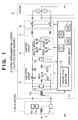
- Fig. 1 is a block diagram showing the arrangement of a system interconnection inverter (an utility connected inverter) 2 according to this embodiment.
- This system interconnection inverter 2 receives a DC power input from a DC power supply 1, converts the DC power into AC power through a converter circuit 5 and inverter circuit 6 with non-insulated input and output, and outputs the AC power to a grounded system 3.
- the system interconnection inverter 2 also has a ground fault detector 13 for detecting a ground fault of the DC power supply 1, and a control circuit 11 which performs control, e.g., controls the input voltage and the intermediate voltage between the converter circuit 5 and the inverter circuit 6 to boost or drop the voltage, thereby causing the potential to ground of the DC power supply 1 to have a value other than a value close to zero.
- a ground fault detector 13 for detecting a ground fault of the DC power supply 1
- control circuit 11 which performs control, e.g., controls the input voltage and the intermediate voltage between the converter circuit 5 and the inverter circuit 6 to boost or drop the voltage, thereby causing the potential to ground of the DC power supply 1 to have a value other than a value close to zero.
- the output from the solar battery 1 is connected to the input terminal of the system interconnection inverter 2.
- the output terminal of the system interconnection inverter 2 is connected to the system 3.
- the solar battery 1 is constituted as a solar battery string having a plurality of solar battery modules la to 1x connected in series such that a voltage appropriate to the input voltage of the system interconnection inverter 2 can be output.
- One solar battery module may suffice as long as a desired voltage can be obtained.
- a plurality of solar battery strings are often connected in parallel to obtain desired power.
- the present invention can be applied even when another DC power supply such as a fuel cell or a battery is used in place of the solar battery 1.
- reference numeral 4 denotes a ground fault generated in the solar battery 1.
- the system 3 is a single-phase three-wire electrical system, and its neutral point is grounded.
- the present invention can be applied to any other grounded system such as single-phase three-wire system, three-phase three-wire system, or three-phase four-wire system.
- the main circuit of the system interconnection inverter 2 comprises the converter circuit 5, inverter circuit 6, interconnection reactor 7, and interconnection switch 8.
- the converter circuit 5 is a so-called chopper-boost DC-to-DC converter constructed by a capacitor 5C1 for smoothing the input voltage to the converter, a boost reactor 5L, a switching element 5Q which switches to control the boost ratio, a diode 5D for preventing any backflow from the output side to the input side of the converter, and a capacitor 5C2 for smoothing the output voltage of the converter.
- a switching element 5Q an IGBT (Isolated Gate Bipolar Transistor) is used.
- a self extinction type element such as a MOSFET may be used.
- the capacitor 5C2 also has a function of smoothing the input voltage to the inverter circuit 6 on the output side.
- the inverter circuit 6 is constituted as a full-bridge circuit having switching elements 6Q1 to 6Q4. As each of the switching elements 6Q1 to 6Q4, an IGBT is used. However, a self extinction type element such as a MOSFET may be used.
- the interconnection reactor 7 obtains a sinusoidal AC current from a rectangular switching voltage.
- the interconnection switch 8 disconnects the solar power generation system from the system 3 when the system interconnection inverter 2 is not operating.
- An input voltage detector 9 detects the voltage input to the system interconnection inverter 2 and outputs an input voltage detection signal representing the input voltage to the control circuit 11.
- An intermediate voltage detector 10 detects the voltage (to be referred to as an "intermediate voltage") at the intermediate portion that is either the output from the converter circuit 5 or the input to the inverter circuit 6, and outputs an intermediate voltage detection signal representing the voltage to the control circuit 11.
- a current detector 12 detects the differential current between the current of the positive line and that of the negative line on the input side, and the ground fault detector 13 determines a ground fault on the basis of whether the detected value has a predetermined level or more, and outputs the result to the control circuit 11 as a ground fault determination signal.
- the current detector 12 need not always be located on the input line of the system interconnection inverter 2, and can be placed at any position, e.g., on the output line of the system interconnection inverter 2 or between the converter circuit 5 and the inverter circuit 6 (to be referred to as an "intermediate line") as long as the differential current between the current of the positive line and that of the negative line can be detected.
- the control circuit 11 controls the operation of the system interconnection inverter 2 on the basis of the input voltage detection signal, intermediate voltage detection signal, and ground fault determination signal, or other detection signal (not shown).
- the control circuit 11 also performs switching control of the converter circuit 5 and inverter circuit 6 and ON/OFF-control of the interconnection switch 8 in accordance with the state.
- the control circuit 11 executes functions prepared in a general system interconnection inverter, i.e., boost control, output waveform control, activation/stop control, MPPT control, interconnection protection, and inverter protection.
- the control circuit 11 also has a potential-to-ground control function for ground fault detection (to be described later).
- the control circuit 11 can be constructed by a digital circuit such as a CPU, DSP (Digital Signal Processor), memory, and I/O, or an analog circuit. Recent CPUs and DSPs enjoy high performance and cost reduction. When these units are used, various kinds of control operations can be implemented by software, resulting in advantages such as size reduction, cost reduction, and improvement of the degree of freedom in design.
- the input voltage and intermediate voltage of the system interconnection inverter 2 are controlled by adjusting the ON/OFF ratio (duty ratio) of the converter circuit 5 or inverter circuit 6.
- the circuit arrangements of the converter circuit 5 and inverter circuit 6 in the present invention are not limited to those shown in Fig. 1.
- the present invention can be applied as far as the system interconnection inverter 2 has non-insulated input and output, and the position where the potential to ground of the solar battery 1 becomes zero changes when the input voltage and/or intermediate voltage changes.
- a potential to ground ranging from VA to VB is present.
- the input voltage Vi and intermediate voltage Vm are almost constant during operation, the voltages VA and VB to ground are also almost constant, and the potential to ground of the solar battery 1 is almost constant.
- the input voltage Vi and/or intermediate voltage Vm is controlled at a predetermined timing to make the absolute value of the potential to ground of the solar battery 1 large, thereby allowing ground fault detection.
- the input voltage Vi is determined and controlled to an almost constant voltage by MPPT control for extracting the maximum output from the solar battery 1. That is, the potential to ground of the solar battery 1 is fixed.
- the system interconnection inverter 2 has the same arrangement as in Fig. 1.
- an intermediate voltage Vm is kept constant, and only an input voltage Vi is changed.
- Fig. 2 is a flow chart showing voltage control in the ground fault detection operation.
- the voltage control is executed by a control circuit 11.
- various initialization operations are executed in step s01, as shown in Fig. 2.
- the control waits until interconnection operation (utility connected operation) starts in step s02. If YES in step s02, the flow advances to step s03.
- step s03 It is determined in step s03 whether the time (to be referred to as an "operation time") from the start of interconnection operation exceeds a second predetermined time T2. If YES in step s03, the flow advances to step s04. Otherwise, the flow returns to step s03.
- step s04 the input power is compared with predetermined power P0. If the input power is smaller than the power P0, it is determined that voltage control for ground fault detection should be executed, and the flow advances to step s06. If the input power is equal to or larger than the power P0, it is determined that voltage control for ground fault detection is still unnecessary, and the flow advances to step s05.
- step s05 It is determined in step s05 whether the operation time exceeds a first predetermined time T1 (> T2). If YES in step s05, it is determined that voltage control for ground fault detection should be executed, and the flow advances to step s06. Otherwise, the flow returns to step s04.
- steps s04 and s05 are repeated.
- step s06 MPPT control that has been performed is inhibited.
- step s07 an input voltage Vin0 at this time is stored.
- step s08 the input voltage Vi is changed from Vin0 to a lowest input voltage Vin1 ( ⁇ Vin0) of the system interconnection inverter 2 at a predetermined rate of change. With this operation, the potential to ground of a solar battery 1 changes. If a ground fault is detected during the period when the input voltage Vi is being dropped, the change in input voltage Vi is stopped, and processing in Fig. 3 for ground fault detection is executed.
- step s22 the input voltage and intermediate voltage at the time of ground fault detection are stored in the memory.
- step s23 an interconnection operation (utility connected operation) stop instruction is output.
- step s24 ground fault detection information representing that a ground fault is detected, the time of detection, and the like is stored together with the input voltage and the like.
- step s25 operation stop processing is executed.
- the ground fault detection information is stored in, e.g. a memory in the control circuit 11, which is backed up by a battery.
- step s08 If no ground fault is detected in step s08, the flow advances to step s09 to quickly change the input voltage Vi to Vin0 to minimize the electric energy loss due to a decrease in power generation efficiency of the solar battery 1.
- step s10 the input voltage Vi is boosted from Vin0 at a predetermined rate of change until the input power obtains a predetermined value close to zero.
- This predetermined value is preferably set to be slightly larger than the no load loss of the system interconnection inverter 2. Instead of making the input power close to zero, the output power may be made close to zero. Even in this case, the result does not change. If a ground fault is detected while the input voltage Vi is being boosted, the same processing for ground fault detection as that for ground fault detection in step s08 is executed.
- step s10 If no ground fault is detected in step s10, the flow advances to step s11 to quickly change the input voltage Vi to Vin0 to minimize the electric energy loss due to a decrease in power generation efficiency of the solar battery 1.
- step s12 inhibition of MPPT control is canceled to resume the MPPT control, and the flow returns to step s03. After returning to step s03, the time from cancel of inhibition of MPPT control is used as the operation time in steps s03 and s05.
- control can be executed to reliably change the potential to ground of the solar battery 1 within the first predetermined time T1.
- the solar battery 1 deviates from an optimum operating point, and the power generation efficiency of the solar battery 1 slightly lowers.
- the control to vary the potential to ground is performed when the power generated by the solar battery 1 is small, and execution of the control to vary the potential to ground is inhibited during the second predetermined time T2, any decrease in power generation efficiency of the solar battery 1 can be suppressed.
- Fig. 4 is a graph showing a variation in potential to ground of the solar battery 1 in the above control.
- a line 41 represents a potential to ground of the positive line of the solar battery 1.
- a line 42 represents a potential to ground of the negative line of the solar battery 1.
- the solar battery 1 has a potential to ground within the range between the two lines 41 and 42.
- the period from the time t0 to t1 corresponds to the state in step s08. During this period, the input voltage Vi is dropped from Vin0 to Vin1 at a predetermined rate of change. Finally, the potential to ground of the positive line of the solar battery 1 becomes VA1. During this period, the potential to ground of the negative line of the solar battery 1 remains VB0.
- the period from the time t1 to t2 corresponds to the state in step s09. During this period, the input voltage Vi is quickly boosted from Vin1 to Vin0. As a result, the potential to ground of the positive line of the solar battery 1 returns to VA0, and that of the negative line of the solar battery 1 remains VB0.
- the period from the time t2 to t3 corresponds to the state in step s10.
- the input voltage Vi is boosted at a predetermined rate of change.
- the input power has a predetermined value which is close to zero and larger than the non-load loss.
- the input voltage is Vin2.
- the potential to ground of the positive line of the solar battery 1 is VA2, and that of the negative line remains VB0.
- the period from time t3 to t4 corresponds to the state in step s11. During this period, the input voltage Vi is quickly dropped from Vin2 to Vin0. At the time t4, the control to vary the potential to ground is temporarily ended. The potential to ground of the positive line of the solar battery 1 returns to VA0, and that of the negative line of the solar battery 1 remains VB0. From the time t4, normal operation is restored.
- the potential to ground of the solar battery 1 is controlled so the voltage does not come close to zero with respect to the ground potential at each portion of the solar battery 1.
- the magnitude of the potential to ground of the solar battery 1 can be made
- a ground fault of a predetermined level or more ground fault resistance value determined by
- the open-circuit voltage of the solar battery 1 is as large as Vin2
- a potential to ground as large as VA2 can be given to the solar battery 1 by controlling to boost the input voltage Vi.
- the insulation resistance is maintained with a resistance value larger than the ground fault of the predetermined level or more.
- the intermediate voltage Vm of the system interconnection inverter 2 is 320 V
- the lowest input voltage Vin1 is 100 V
- the level (ground fault detection level) at which a ground fault detector 13 detects a ground fault is 25 mA.
- the optimum operating point voltage of the solar battery 1 is 190 V
- the potential VB0 to ground of the negative line of the solar battery is -160 V.
- the input voltage Vin0 in the normal operation mode is 190 V.
- the input voltage is about 240 V. That is, the voltage Vin2 is 240 V.
- the input voltage at the time t1 is Vin1
- the potential VA1 to ground of the positive line is -60 V.
- the potential VA2 to ground of the positive line is +80 V.
- the position of the negative terminal of the solar battery 1 is represented by 0, the position of the positive terminal is represented by 1, and an arbitrary position in the solar battery 1 is represented by x (0 ⁇ x ⁇ 1).
- Vin be the input voltage
- VB be the potential to ground of the negative line.
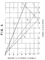
- Fig. 5 shows the magnitudes
- At the time tl at least 60 V is ensured as the magnitude
- At the time t3 as the magnitude
- of the potential to ground is minimized at 66 V when the position x is 0.94.
- the distribution of potentials to ground is indicated by the dotted line t0. That is, the potential to ground is close to zero near the position x represented by 0.84.
- a ground fault near the position x represented by 0.84 (dead region) is particularly hard to detect.
- a sufficient potential to ground is given even near the position x represented by 0.84.
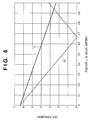
- Fig. 6 is a graph showing the boundaries of detectable ground fault resistance values that are obtained from the values shown in Fig. 5 and the ground fault detection level (25 mA) of the ground fault detector 13.
- the abscissa represents the position x in the solar battery 1, and the ordinate represents the resistance value between the position x and the ground potential.
- the region below the solid line t1 or broken line t3 is a region where a ground fault can be detected at the time t1 or t3.
- the region above the solid line t1 or broken line t3 is a region where a ground fault cannot be detected at the time tl or t3.
- the potential to ground of the solar battery is controlled by changing the input voltage, and a predetermined value or more except a value close to zero is ensured at all positions in the solar battery as the magnitude of the potential to ground of the solar battery, thereby detecting a ground fault in the dead region, which cannot be detected in normal operation. If no ground fault is detected in controlling the potential to ground, it is confirmed that a predetermined resistance value is maintained between the ground potential and each portion in the solar battery.
- the situations of the input voltage, intermediate voltage, and the like at the time of ground fault detection and the time of ground fault detection are recorded on the memory. After a ground fault occurs, the record is analyzed and used as reference for inspection of the ground fault generation situation.
- the potential to ground is controlled within the first predetermined time T1
- a ground fault can be detected within the first predetermined time T1 after the ground fault has occurred. Since the interval of control of the potential to ground is set to the second predetermined time T2 or more, electric energy loss due to a decrease in power generation efficiency of the solar battery in controlling'the solar battery can be suppressed. Since the potential to ground is controlled when the input or output power has a predetermined value or less, electric energy loss due to a decrease in power generation efficiency of the solar battery in controlling the solar battery can be suppressed.
- the control waits for a predetermined time after the stop of operation of the system interconnection inverter. Then, the system interconnection inverter is operated again, and the potential to ground is controlled to repeat ground fault detection (to be referred to as "redetection") once or a plurality of number of times, thereby preventing any detection error due to external noise. In addition, when the ground fault state was canceled can be known.
- the lowest input voltage is as low as about 100 V.
- the potential to ground can be reliably given by controlling the input voltage to (almost) the lowest input voltage.
- a ground fault can be accurately detected when the potential to ground is slowly changed by controlling the input voltage.
- the potential to ground is preferably varied at a rate of change lower than that in the normal mode.
- the ground fault detection operation of controlling the potential to ground may be executed at the start of interconnection operation or while the normal operation is stopped.
- the recording of the detected intermediate voltage is not always necessary.
- the same effect is obtained by using the predetermined fixed value instead of the detected intermediate voltage.
- the system interconnection inverter (the utility connected inverter) of the second embodiment has the arrangement of a system interconnection inverter (an utility connected inverter) 2 shown in Fig. 1, as in the first embodiment.
- the input voltage is controlled to control the potential to ground.
- the intermediate voltage is controlled.
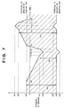
- Fig. 7 is a graph showing a variation in' potential to ground of a solar battery 1 when both the input voltage and the intermediate voltage are controlled, in which the abscissa represents time, and the ordinate represents the potential to ground of the solar battery 1, as in Fig. 4. Normal operation continues until time t10. During this period, the potential to ground of the positive line of the solar battery 1 is VA0, and that of the negative line of the solar battery 1 is VB0.
- Control to vary the potential to ground is executed from the time t10. From the time t10 to t11, an input voltage Vi is dropped from Vin0 to Vin1 at a predetermined rate of change. At the time t11, the potential to ground of the positive line of the solar battery 1 becomes VA1. The potential to ground of the negative line of the solar battery 1 is kept unchanged at VB0.
- an intermediate voltage Vm is boosted from 2VB0 to 2VB1 at a predetermined rate of change.
- the potential to ground of the positive line of the solar battery 1 becomes VA3.
- the potential to ground of the negative line of the solar battery 1 becomes VB1.
- the intermediate voltage Vm is dropped from 2VB1 to 2VB0 at a predetermined rate of change.
- the potential to ground of the positive line of the solar battery 1 becomes VA1.
- the potential to ground of the negative line of the solar battery 1 returns to VB0.
- the input voltage Vi is quickly boosted from Vin1 to Vin0.
- the potential to ground of the positive line of the solar battery 1 returns to VA0.
- the potential to ground of the negative line of the solar battery 1 is kept unchanged at VB0.
- the input voltage Vi is boosted at a predetermined rate of change.
- the input power has a predetermined value which is close to zero and larger than the non-load loss.
- the input voltage Vi is Vin2.
- the potential to ground of the positive line of the solar battery 1 becomes VA2.
- the potential to ground of the negative line of the solar battery 1 is kept unchanged at VB0.
- the intermediate voltage Vm is dropped from 2VB0 to 2VB2 at a predetermined rate of change.
- the potential to ground of the positive line of the solar battery 1 becomes VA4.
- the potential to ground of the negative line of the solar battery 1 becomes VB2.
- the intermediate voltage Vm is boosted from 2VB2 to 2VB0 at a predetermined rate of change.
- the potential to ground of the positive line of the solar battery 1 becomes VA2.
- the potential to ground of the negative line of the solar battery 1 returns to VB0.
- the input voltage Vi is quickly dropped from Vin2 to Vin0.
- control to vary the potential to ground is temporarily ended.
- the potential to ground of the positive line of the solar battery 1 returns to VA0.
- the potential to ground of the negative line of the solar battery 1 is kept unchanged at VB0. From the time t18, normal operation is restored.
- the potential to ground of the solar battery 1 is controlled so the voltage does not come close to zero with respect to the ground potential at each portion of the solar battery 1.
- the magnitude of the potential to ground of the solar battery 1 can be made
- the open-circuit voltage of the solar battery 1 is as large as Vin2
- a potential to ground as large as VA4 can be given to the solar battery 1 by boosting the input voltage Vi and dropping the intermediate voltage Vm.
- the insulation resistance is maintained with a resistance value larger than the ground fault of the predetermined level or more.
- the intermediate voltage 2VB1 of the system interconnection inverter 2 is 340 V
- the intermediate voltage 2VB2 is 300 V
- the lowest input voltage Vin1 is 100 V
- the ground fault detection level of a ground fault detector 13 is 25 mA.
- the optimum operating point voltage of the solar battery 1 is 190 V
- the intermediate voltage 2VB1 is 340 V
- the potential VB0 to ground of the negative line of the solar battery 1 is -170 V.
- the intermediate voltage 2VB2 is 300 V
- the potential VB0 to ground of the negative line of the solar battery 1 is -150 V.
- the input voltage Vin0 in the normal operation mode is 190 V.
- the input voltage is about 240 V. That is, the voltage Vin2 is 240 V.
- the potential VA1 to ground of the positive line is -70 V.
- the potential VA1 to ground of the positive line is +90 V.
- Fig. 8 shows the magnitudes
- Fig. 8 is a graph like Fig. 5, in which the abscissa represents the position x in the solar battery 1, and the ordinate represents the magnitude
- of the potential to ground unit: volt.
- of the potential to ground a value lager than that at the time t12 is ensured in a region where the position x in the solar battery 1 is 0.94 or more, as is indicated by the broken line t16.
- of the potential to ground in the solar battery 1 is 76 V at the position x represented by 0.94. This is a much larger value than that in the first embodiment, 66 V. It means that a ground fault with a larger ground fault resistance value can be detected. It also means that a ground fault can be more sensitively detected at all positions in the solar' battery 1 as compared to the first embodiment.
- the potential to ground of the solar battery is controlled by changing the input voltage and intermediate voltage, and a predetermined value or more except a value close to zero is ensured at all positions in the solar battery as the magnitude of the potential to ground of the solar battery, thereby detecting a ground fault in the dead region, which cannot be detected in normal operation, as in the first embodiment.
- a ground fault with a larger ground fault resistance value can be detected as compared to a case wherein only the input voltage is changed.
- control In reducing the intermediate voltage in controlling the potential to ground, control must be performed in consideration of the voltage of a system 3. More specifically, even when the intermediate voltage is dropped, the voltage value must be kept sufficiently larger than the peak value of the AC voltage of the system 3.
- the third embodiment will be described next.
- the system interconnection inverter (utility connected inverter) of the third embodiment has the arrangement of a system interconnection inverter (an utility connected inverter) 2 shown in Fig. 1, as in the first embodiment.
- the potential to ground is controlled by controlling the input voltage, as shown in Fig. 4 of the first embodiment.
- the distribution of potentials to ground in a solar battery 1 is the same as in Fig. 5.
- the third embodiment is different from the first embodiment in that a ground fault detector 13 has two ground fault detection levels.
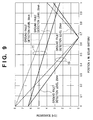
- Fig. 9 is a graph showing the boundaries of detectable ground fault resistance values that are obtained from the values shown in Fig. 5 and the ground fault detection levels (25 mA and 20 mA) of the ground fault detector 13.
- the abscissa represents a position x in the solar battery 1, and the ordinate represents the resistance value between the position x and the ground potential.
- the two solid lines indicate the detection boundaries at the ground fault detection level of 25 mA.
- the two broken lines indicate the detection boundaries at the ground fault detection level of 20 mA.
- the two broken lines indicating boundaries for the ground fault detection level of 20 mA are added.
- the region below each line is a ground fault detectable region, and the region above each line is a ground fault undetectable region.
- the ground fault resistance Rx and its position x are almost obtained.
- the detected value of the input voltage Vin or intermediate voltage Vm or the calculated value of the ground fault resistance value Rx or position x, or both of these values are stored in the memory, the user can easily and quickly take a measure after detecting a ground fault.
- the ground fault detection levels are not limited to the above values. Not two but three or more ground fault detection levels may be prepared. In this case, since three or more ground fault detection values can be used to estimate the ground fault resistance value Rx and position x, the estimation accuracy improves.
- the fourth embodiment will be described next.
- the system interconnection inverter (utility connected inverter) of the fourth embodiment has the arrangement of a system interconnection inverter 2 shown in Fig. 1, as in the first embodiment.
- the potential to ground is controlled by controlling the input voltage, as shown in Fig. 4 of the first embodiment.
- the distribution of potentials to ground in a solar battery 1 is the same as in Fig. 5.
- the fourth embodiment is different from the first embodiment in that a ground fault detector 13 outputs a value (to be referred to as a "ground current detection value" hereinafter) I of a detected ground current.
- a relationship Rx ⁇ I ⁇ Vin ⁇ x + VB holds, as described in the third embodiment.
- a ground fault resistance Rx and ground fault position x can be calculated.
- the detected value of the input voltage Vin, intermediate voltage Vm, or ground current detection value I, or the calculated value of the ground fault resistance value Rx or position x, or both of these values are stored in the memory, the user can easily and quickly take a measure after the ground fault detection.
- a change in ground fault resistance value Rx may be taken into consideration on the basis of log information recorded in the memory when the ground fault is detected.
- the minimum number of samples necessary to calculate the ground fault resistance value Rx and ground fault position x is two. When three or more samples are used for calculation, the calculation accuracy can be improved.
- the methods of controlling the potential to ground in the above embodiments are merely examples, and any other method can be used as long as the input voltage and/or intermediate voltage of the system interconnection inverter is controlled to control the potential to ground to a voltage value other than a value close to zero (or a predetermined or more voltage value) in all regions of the solar battery.
- a method of controlling the potential to ground not the input voltage but only the intermediate voltage may be controlled. In this case, since the input voltage does not deviate from an optimum operating point voltage of the solar battery, the power generation efficiency of the solar battery can be kept high.
- the measure after ground fault detection is efficiently performed even if a time has elapsed from the ground fault detection, and the ground fault position is unknown by which the ground resistance becomes high.
- the object is to reliably detect a ground fault of a solar battery.
- DC power input from a solar battery is converted into AC power and supplied to a system.
- a system interconnection inverter (utility connected inverter) having non-insulated input and output
- the input voltage of a converter circuit and/or the intermediate voltage between the converter circuit and an inverter circuit are varied to control the potential to ground at each portion of the solar battery to a value other than a value close to zero.
Applications Claiming Priority (2)
| Application Number | Priority Date | Filing Date | Title |
|---|---|---|---|
| JP2000092087 | 2000-03-29 | ||
| JP2000092087A JP2001275259A (ja) | 2000-03-29 | 2000-03-29 | 系統連系インバータおよび分散形発電システム |
Publications (3)
| Publication Number | Publication Date |
|---|---|
| EP1143594A2 true EP1143594A2 (fr) | 2001-10-10 |
| EP1143594A3 EP1143594A3 (fr) | 2005-10-12 |
| EP1143594B1 EP1143594B1 (fr) | 2010-05-19 |
Family
ID=18607478
Family Applications (1)
| Application Number | Title | Priority Date | Filing Date |
|---|---|---|---|
| EP01107939A Expired - Lifetime EP1143594B1 (fr) | 2000-03-29 | 2001-03-28 | Dispositif de convertisseur de puissance, procédé pour sa commmande, et appareil de génération d'énergie solaire |
Country Status (6)
| Country | Link |
|---|---|
| US (1) | US7079406B2 (fr) |
| EP (1) | EP1143594B1 (fr) |
| JP (1) | JP2001275259A (fr) |
| AT (1) | ATE468650T1 (fr) |
| AU (1) | AU763844B2 (fr) |
| DE (1) | DE60142145D1 (fr) |
Cited By (62)
| Publication number | Priority date | Publication date | Assignee | Title |
|---|---|---|---|---|
| EP1235339A2 (fr) * | 2001-02-26 | 2002-08-28 | Canon Kabushiki Kaisha | Onduleur, circuit d'alimentation de puissance et méthode pour réduire les courants de fuite dans le circuit d'alimentation de puissance |
| EP1403649A2 (fr) * | 2002-09-30 | 2004-03-31 | Siemens Aktiengesellschaft | Procédé et appareil pour tester des générateurs photovoltaics |
| WO2005057770A1 (fr) * | 2003-12-09 | 2005-06-23 | Toyota Jidosha Kabushiki Kaisha | Convertisseur de courant et vehicule equipe de ce dernier |
| WO2010078669A1 (fr) * | 2009-01-08 | 2010-07-15 | Iworks Ag | Dispositif pour centrales photovoltaïques destiné à régler le potentiel électrique de générateurs photovoltaïques |
| EP2393153A1 (fr) * | 2010-06-07 | 2011-12-07 | Samsung SDI Co., Ltd. | Système de stockage d'énergie |
| AT512780A4 (de) * | 2012-06-13 | 2013-11-15 | Fronius Int Gmbh | Schaltnetzteil sowie Wechselrichter und Strangüberwachung mit einem solchen Schaltnetzteil |
| WO2013178654A1 (fr) * | 2012-06-01 | 2013-12-05 | Sma Solar Technology Ag | Mesure de résistance diélectrique pour onduleur |
| WO2014048476A1 (fr) * | 2012-09-27 | 2014-04-03 | Siemens Aktiengesellschaft | Dispositif électrique à section d'isolation réduite |
| CN103901318A (zh) * | 2012-12-26 | 2014-07-02 | 通用电气公司 | 在能量转换系统中定位接地故障和绝缘降级状况的方法 |
| US9065345B2 (en) | 2008-07-09 | 2015-06-23 | Sma Solar Technology Ag | Transformerless inverter comprising a DC/DC converter |
| US9112379B2 (en) | 2006-12-06 | 2015-08-18 | Solaredge Technologies Ltd. | Pairing of components in a direct current distributed power generation system |
| US9130401B2 (en) | 2006-12-06 | 2015-09-08 | Solaredge Technologies Ltd. | Distributed power harvesting systems using DC power sources |
| EP2963794A1 (fr) * | 2014-06-30 | 2016-01-06 | Aisin Seiki Kabushiki Kaisha | Dispositif d'interconnexion de système pour alimentation décentralisée |
| EP2963762A1 (fr) * | 2014-06-30 | 2016-01-06 | Sungrow Power Supply Co., Ltd. | Procédé de suppression de tension flottante, dispositif, système de commande d'onduleur et onduleur |
| US9235228B2 (en) | 2012-03-05 | 2016-01-12 | Solaredge Technologies Ltd. | Direct current link circuit |
| US9291696B2 (en) | 2007-12-05 | 2016-03-22 | Solaredge Technologies Ltd. | Photovoltaic system power tracking method |
| US9318974B2 (en) | 2014-03-26 | 2016-04-19 | Solaredge Technologies Ltd. | Multi-level inverter with flying capacitor topology |
| US9362743B2 (en) | 2008-05-05 | 2016-06-07 | Solaredge Technologies Ltd. | Direct current power combiner |
| US9368964B2 (en) | 2006-12-06 | 2016-06-14 | Solaredge Technologies Ltd. | Distributed power system using direct current power sources |
| US9401599B2 (en) | 2010-12-09 | 2016-07-26 | Solaredge Technologies Ltd. | Disconnection of a string carrying direct current power |
| US9407161B2 (en) | 2007-12-05 | 2016-08-02 | Solaredge Technologies Ltd. | Parallel connected inverters |
| US9537445B2 (en) | 2008-12-04 | 2017-01-03 | Solaredge Technologies Ltd. | Testing of a photovoltaic panel |
| US9543889B2 (en) | 2006-12-06 | 2017-01-10 | Solaredge Technologies Ltd. | Distributed power harvesting systems using DC power sources |
| US9548619B2 (en) | 2013-03-14 | 2017-01-17 | Solaredge Technologies Ltd. | Method and apparatus for storing and depleting energy |
| US9590526B2 (en) | 2006-12-06 | 2017-03-07 | Solaredge Technologies Ltd. | Safety mechanisms, wake up and shutdown methods in distributed power installations |
| US9647442B2 (en) | 2010-11-09 | 2017-05-09 | Solaredge Technologies Ltd. | Arc detection and prevention in a power generation system |
| US9644993B2 (en) | 2006-12-06 | 2017-05-09 | Solaredge Technologies Ltd. | Monitoring of distributed power harvesting systems using DC power sources |
| US9673711B2 (en) | 2007-08-06 | 2017-06-06 | Solaredge Technologies Ltd. | Digital average input current control in power converter |
| US9680304B2 (en) | 2006-12-06 | 2017-06-13 | Solaredge Technologies Ltd. | Method for distributed power harvesting using DC power sources |
| US9812984B2 (en) | 2012-01-30 | 2017-11-07 | Solaredge Technologies Ltd. | Maximizing power in a photovoltaic distributed power system |
| US9819178B2 (en) | 2013-03-15 | 2017-11-14 | Solaredge Technologies Ltd. | Bypass mechanism |
| US9831824B2 (en) | 2007-12-05 | 2017-11-28 | SolareEdge Technologies Ltd. | Current sensing on a MOSFET |
| US9853538B2 (en) | 2007-12-04 | 2017-12-26 | Solaredge Technologies Ltd. | Distributed power harvesting systems using DC power sources |
| US9853565B2 (en) | 2012-01-30 | 2017-12-26 | Solaredge Technologies Ltd. | Maximized power in a photovoltaic distributed power system |
| US9866098B2 (en) | 2011-01-12 | 2018-01-09 | Solaredge Technologies Ltd. | Serially connected inverters |
| US9869701B2 (en) | 2009-05-26 | 2018-01-16 | Solaredge Technologies Ltd. | Theft detection and prevention in a power generation system |
| US9876430B2 (en) | 2008-03-24 | 2018-01-23 | Solaredge Technologies Ltd. | Zero voltage switching |
| US9923516B2 (en) | 2012-01-30 | 2018-03-20 | Solaredge Technologies Ltd. | Photovoltaic panel circuitry |
| US9941813B2 (en) | 2013-03-14 | 2018-04-10 | Solaredge Technologies Ltd. | High frequency multi-level inverter |
| US9960667B2 (en) | 2006-12-06 | 2018-05-01 | Solaredge Technologies Ltd. | System and method for protection during inverter shutdown in distributed power installations |
| US9966766B2 (en) | 2006-12-06 | 2018-05-08 | Solaredge Technologies Ltd. | Battery power delivery module |
| EP2377234B1 (fr) * | 2008-12-20 | 2018-10-10 | SMA Solar Technology AG | Onduleur sans transformateur avec un convertisseur dc/dc |
| US10115841B2 (en) | 2012-06-04 | 2018-10-30 | Solaredge Technologies Ltd. | Integrated photovoltaic panel circuitry |
| US10230310B2 (en) | 2016-04-05 | 2019-03-12 | Solaredge Technologies Ltd | Safety switch for photovoltaic systems |
| US10396662B2 (en) | 2011-09-12 | 2019-08-27 | Solaredge Technologies Ltd | Direct current link circuit |
| US10673229B2 (en) | 2010-11-09 | 2020-06-02 | Solaredge Technologies Ltd. | Arc detection and prevention in a power generation system |
| US10673222B2 (en) | 2010-11-09 | 2020-06-02 | Solaredge Technologies Ltd. | Arc detection and prevention in a power generation system |
| US10910834B2 (en) | 2003-05-28 | 2021-02-02 | Solaredge Technologies Ltd. | Power converter for a solar panel |
| US10931119B2 (en) | 2012-01-11 | 2021-02-23 | Solaredge Technologies Ltd. | Photovoltaic module |
| US11018623B2 (en) | 2016-04-05 | 2021-05-25 | Solaredge Technologies Ltd. | Safety switch for photovoltaic systems |
| US11177663B2 (en) | 2016-04-05 | 2021-11-16 | Solaredge Technologies Ltd. | Chain of power devices |
| US11264947B2 (en) | 2007-12-05 | 2022-03-01 | Solaredge Technologies Ltd. | Testing of a photovoltaic panel |
| US11296650B2 (en) | 2006-12-06 | 2022-04-05 | Solaredge Technologies Ltd. | System and method for protection during inverter shutdown in distributed power installations |
| US11309832B2 (en) | 2006-12-06 | 2022-04-19 | Solaredge Technologies Ltd. | Distributed power harvesting systems using DC power sources |
| US11569660B2 (en) | 2006-12-06 | 2023-01-31 | Solaredge Technologies Ltd. | Distributed power harvesting systems using DC power sources |
| US11569659B2 (en) | 2006-12-06 | 2023-01-31 | Solaredge Technologies Ltd. | Distributed power harvesting systems using DC power sources |
| US11687112B2 (en) | 2006-12-06 | 2023-06-27 | Solaredge Technologies Ltd. | Distributed power harvesting systems using DC power sources |
| US11728768B2 (en) | 2006-12-06 | 2023-08-15 | Solaredge Technologies Ltd. | Pairing of components in a direct current distributed power generation system |
| US11735910B2 (en) | 2006-12-06 | 2023-08-22 | Solaredge Technologies Ltd. | Distributed power system using direct current power sources |
| US11855231B2 (en) | 2006-12-06 | 2023-12-26 | Solaredge Technologies Ltd. | Distributed power harvesting systems using DC power sources |
| US11881814B2 (en) | 2005-12-05 | 2024-01-23 | Solaredge Technologies Ltd. | Testing of a photovoltaic panel |
| US11888387B2 (en) | 2006-12-06 | 2024-01-30 | Solaredge Technologies Ltd. | Safety mechanisms, wake up and shutdown methods in distributed power installations |
Families Citing this family (76)
| Publication number | Priority date | Publication date | Assignee | Title |
|---|---|---|---|---|
| JP2001345472A (ja) * | 2000-03-29 | 2001-12-14 | Canon Inc | 太陽電池モジュールの検査方法、検査装置及び製造方法、太陽光発電システムの点検方法及び点検装置、並びに絶縁抵抗測定器及び耐電圧試験器 |
| JP2002318162A (ja) * | 2001-02-01 | 2002-10-31 | Canon Inc | 異常の検知方法および保護装置、並びに、温度の推定方法および推定装置 |
| JP4829424B2 (ja) * | 2001-05-31 | 2011-12-07 | キヤノン株式会社 | 太陽電池アレイ及び太陽光発電システム |
| JP2003158282A (ja) * | 2001-08-30 | 2003-05-30 | Canon Inc | 太陽光発電システム |
| JP2003180036A (ja) | 2001-10-01 | 2003-06-27 | Canon Inc | 電力変換装置、電力変換システム、及び単独運転検出方法 |
| JP4153211B2 (ja) * | 2002-01-31 | 2008-09-24 | 東芝三菱電機産業システム株式会社 | インバータ装置 |
| JP4585774B2 (ja) * | 2003-03-07 | 2010-11-24 | キヤノン株式会社 | 電力変換装置および電源装置 |
| JP4160919B2 (ja) * | 2004-03-24 | 2008-10-08 | シャープ株式会社 | インバータ装置 |
| US7362557B2 (en) * | 2004-03-30 | 2008-04-22 | Continental Automotive Systems U.S. Inc. | Method, apparatus and article for bi-directional DC/DC power conversion |
| JP2005312138A (ja) * | 2004-04-19 | 2005-11-04 | Canon Inc | 電力制御装置、発電システム及び電力系統システム |
| US20050231153A1 (en) * | 2004-04-20 | 2005-10-20 | Scott Dewey | High voltage isolation detection of a fuel cell system using magnetic field cancellation |
| US7317316B2 (en) * | 2004-07-02 | 2008-01-08 | Nucellsys Gmbh | Apparatus and method for measuring the insulation resistance of a fuel cell system |
| JP2006101668A (ja) * | 2004-09-30 | 2006-04-13 | Honda Motor Co Ltd | 電源装置 |
| JP4680575B2 (ja) * | 2004-11-29 | 2011-05-11 | 三菱電機株式会社 | インバータ装置 |
| JP2006211782A (ja) * | 2005-01-26 | 2006-08-10 | Yaskawa Electric Corp | サーボ制御装置 |
| US7862944B2 (en) * | 2005-07-13 | 2011-01-04 | Gm Global Technology Operations, Inc. | Method for detection and diagnosis of isolation faults in fuel cell hybrid vehicles |
| US8324921B2 (en) | 2007-12-05 | 2012-12-04 | Solaredge Technologies Ltd. | Testing of a photovoltaic panel |
| DE102006022686B4 (de) * | 2006-05-16 | 2018-03-15 | Sma Solar Technology Ag | Messanordnung zur Ermittlung des Isolationswiderstandes einer elektrischen Vorrichtung oder einer Anlage |
| TWI328730B (en) * | 2006-06-16 | 2010-08-11 | Ablerex Electronics Co Ltd | Maximum power point tracking method and tracker thereof for a solar power system |
| JP2008059084A (ja) * | 2006-08-29 | 2008-03-13 | Toshiba Kyaria Kk | 系統連系インバータ |
| TWI320626B (en) * | 2006-09-12 | 2010-02-11 | Ablerex Electronics Co Ltd | Bidirectional active power conditioner |
| WO2008047439A1 (fr) * | 2006-10-19 | 2008-04-24 | Mitsubishi Electric Corporation | Convertisseur de puissance |
| US7900361B2 (en) | 2006-12-06 | 2011-03-08 | Solaredge, Ltd. | Current bypass for distributed power harvesting systems using DC power sources |
| US20080144294A1 (en) * | 2006-12-06 | 2008-06-19 | Meir Adest | Removal component cartridge for increasing reliability in power harvesting systems |
| US8467160B2 (en) * | 2007-03-06 | 2013-06-18 | Xantrex Technology, Inc. | Bipolar DC to AC power converter with DC ground fault interrupt |
| US9172296B2 (en) * | 2007-05-23 | 2015-10-27 | Advanced Energy Industries, Inc. | Common mode filter system and method for a solar power inverter |
| US8203069B2 (en) * | 2007-08-03 | 2012-06-19 | Advanced Energy Industries, Inc | System, method, and apparatus for coupling photovoltaic arrays |
| US7768751B2 (en) * | 2008-01-29 | 2010-08-03 | Advanced Energy Industries, Inc. | System and method for ground fault detection and interruption |
| US8294296B2 (en) * | 2007-08-03 | 2012-10-23 | Advanced Energy Industries, Inc. | System, method, and apparatus for remotely coupling photovoltaic arrays |
| US20090217964A1 (en) * | 2007-09-26 | 2009-09-03 | Advanced Energy Industries, Inc. | Device, system, and method for improving the efficiency of solar panels |
| US20090078304A1 (en) * | 2007-09-26 | 2009-03-26 | Jack Arthur Gilmore | Photovoltaic charge abatement device, system, and method |
| US7964837B2 (en) * | 2007-12-31 | 2011-06-21 | Advanced Energy Industries, Inc. | Photovoltaic inverter interface device, system, and method |
| US8269451B2 (en) * | 2008-01-10 | 2012-09-18 | Mitsubishi Electric Corporation | Power conversion device |
| US8630098B2 (en) * | 2008-06-12 | 2014-01-14 | Solaredge Technologies Ltd. | Switching circuit layout with heatsink |
| US7619200B1 (en) * | 2008-08-10 | 2009-11-17 | Advanced Energy Industries, Inc. | Device system and method for coupling multiple photovoltaic arrays |
| US8461508B2 (en) | 2008-08-10 | 2013-06-11 | Advanced Energy Industries, Inc. | Device, system, and method for sectioning and coupling multiple photovoltaic strings |
| EP2190110B1 (fr) * | 2008-11-25 | 2012-10-10 | SMA Solar Technology AG | Détermination de la capacité de charge d'une source de courant continu pouvant être connectée au réseau sur un interrupteur et un onduleur au réseau |
| US8362644B2 (en) * | 2008-12-02 | 2013-01-29 | Advanced Energy Industries, Inc. | Device, system, and method for managing an application of power from photovoltaic arrays |
| US8233301B1 (en) | 2008-12-20 | 2012-07-31 | Sensorlink Corporation | Impedance dropping dc power supply having an impedance controlled converter |
| TWI368376B (en) * | 2009-01-17 | 2012-07-11 | Ablerex Electronics Co Ltd | Three-armed power transforming apparatus |
| JP4888817B2 (ja) * | 2009-03-13 | 2012-02-29 | オムロン株式会社 | パワーコンディショナおよび太陽光発電システム |
| US8085565B2 (en) * | 2009-04-08 | 2011-12-27 | Lear Corporation | Vehicle inverter for powering consumer electronic devices |
| CN104158483B (zh) | 2009-05-22 | 2017-09-12 | 太阳能安吉科技有限公司 | 电隔离的散热接线盒 |
| US8303349B2 (en) | 2009-05-22 | 2012-11-06 | Solaredge Technologies Ltd. | Dual compressive connector |
| US8690110B2 (en) | 2009-05-25 | 2014-04-08 | Solaredge Technologies Ltd. | Bracket for connection of a junction box to photovoltaic panels |
| BRPI0903548B1 (pt) * | 2009-06-05 | 2019-06-25 | Indústria De Motores Anauger S.a | Sistema de alimentação para uma carga indutiva a partir de uma fonte de energia com potência variável e sistema de alimentação para uma bomba vibratória a partir de células solares |
| EP2282388A1 (fr) * | 2009-08-06 | 2011-02-09 | SMA Solar Technology AG | Dispositif d'alimentation en énergie électrique d'une multitude de chaînes de modules photovoltaïques dans un réseau électrique |
| CN102484372B (zh) * | 2009-08-24 | 2014-06-18 | 三菱电机株式会社 | 太阳能发电用功率调节器 |
| US8710699B2 (en) | 2009-12-01 | 2014-04-29 | Solaredge Technologies Ltd. | Dual use photovoltaic system |
| EP2530818A4 (fr) * | 2010-01-25 | 2017-05-10 | Panasonic Intellectual Property Management Co., Ltd. | Appareil de conversion de puissance, appareil de connexion réseau, et système de connexion réseau |
| US8766696B2 (en) | 2010-01-27 | 2014-07-01 | Solaredge Technologies Ltd. | Fast voltage level shifter circuit |
| JP5605548B2 (ja) * | 2010-04-12 | 2014-10-15 | 富士電機株式会社 | 系統連系装置 |
| CN103081268B (zh) | 2010-08-20 | 2016-01-20 | 东芝三菱电机产业系统株式会社 | 接地装置 |
| US20120049627A1 (en) * | 2010-08-24 | 2012-03-01 | Sanyo Electric Co., Ltd. | Current collecting box for photovoltaic power generation |
| JP5987903B2 (ja) * | 2011-06-01 | 2016-09-07 | エンフェイズ エナジー インコーポレイテッド | 送電網インピーダンス検出のための方法及び装置 |
| JP5646752B2 (ja) * | 2011-06-28 | 2014-12-24 | 京セラ株式会社 | 系統連系インバータ装置およびその制御方法 |
| US8941956B2 (en) * | 2011-07-26 | 2015-01-27 | Railpower, Llc | Switching ground tether circuit |
| US9297862B2 (en) | 2011-07-28 | 2016-03-29 | Eaton Corporation | Systems and apparatus for fault detection in DC power sources using AC residual current detection |
| CN102957151A (zh) * | 2011-08-22 | 2013-03-06 | 台达电子企业管理(上海)有限公司 | 一种用于可再生能源系统的功率补偿装置及其方法 |
| JP2013097596A (ja) * | 2011-11-01 | 2013-05-20 | Sony Corp | 太陽電池システム、電子機器および建築物 |
| EP3499695A1 (fr) | 2012-05-25 | 2019-06-19 | Solaredge Technologies Ltd. | Circuit pour sources interconnectées de courant continu |
| TWI477046B (zh) * | 2012-09-26 | 2015-03-11 | Univ Nat Kaohsiung Applied Sci | 太陽能電池陣列正電位端接地之市電併聯型太陽能發電系統 |
| EP2779345B8 (fr) * | 2013-03-14 | 2015-06-10 | ABB Technology Oy | Procédé de commande de branche de commutation d'un convertisseur active clampé par le neutre à trois niveaux et branche de commutation pour celui-ci |
| JP6541485B2 (ja) * | 2015-07-15 | 2019-07-10 | 三菱電機株式会社 | 駅舎補助電源用地絡検出装置 |
| DE102015111804B3 (de) * | 2015-07-21 | 2016-12-15 | Sma Solar Technology Ag | Verfahren zum betrieb eines wechselrichters und wechselrichter, sowie photovoltaikanlage |
| NZ741164A (en) * | 2015-09-08 | 2023-03-31 | Volt Tech Limited | Battery with a voltage regulation device |
| US10599113B2 (en) | 2016-03-03 | 2020-03-24 | Solaredge Technologies Ltd. | Apparatus and method for determining an order of power devices in power generation systems |
| US11081608B2 (en) | 2016-03-03 | 2021-08-03 | Solaredge Technologies Ltd. | Apparatus and method for determining an order of power devices in power generation systems |
| CN107153212B (zh) | 2016-03-03 | 2023-07-28 | 太阳能安吉科技有限公司 | 用于映射发电设施的方法 |
| US10381838B2 (en) * | 2016-05-10 | 2019-08-13 | Tesla, Inc. | Power control system with fault detection and data retention for energy generation systems |
| US10103665B2 (en) * | 2017-01-06 | 2018-10-16 | General Electric Company | Protection for redundancy of isolated inverter blocks |
| JP6979822B2 (ja) * | 2017-07-28 | 2021-12-15 | 住友電気工業株式会社 | 電力変換装置、地絡箇所の電圧推定方法、及び、分散型電源システム |
| JP6930370B2 (ja) | 2017-10-30 | 2021-09-01 | オムロン株式会社 | 地絡検出装置 |
| US10756532B2 (en) * | 2018-07-13 | 2020-08-25 | Kohler Co. | Ground fault minimization |
| US10848053B2 (en) * | 2018-07-13 | 2020-11-24 | Kohler Co. | Robust inverter topology |
| CN112701334B (zh) * | 2020-12-25 | 2023-03-21 | 上海韵量新能源科技有限公司 | 电堆中膜电极阴阳极颠倒的诊断方法 |
Citations (6)
| Publication number | Priority date | Publication date | Assignee | Title |
|---|---|---|---|---|
| EP0679898A2 (fr) * | 1994-04-30 | 1995-11-02 | Canon Kabushiki Kaisha | Procédé de mesure de l'état d'isolation pour un système décentralisé générateur de puissance |
| JPH0984254A (ja) * | 1995-09-14 | 1997-03-28 | Omron Corp | 電源装置、インバータ装置および分散型電源装置 |
| JPH09285015A (ja) * | 1996-04-08 | 1997-10-31 | Sanyo Electric Co Ltd | 太陽光発電システムの直流地絡検出装置 |
| EP0878850A2 (fr) * | 1997-05-14 | 1998-11-18 | Canon Kabushiki Kaisha | Dispositif de production d'énergie par effet photovoltaique |
| EP0884817A2 (fr) * | 1997-06-13 | 1998-12-16 | Canon Kabushiki Kaisha | Dispositif et procédé de protection contre défaut à la terre d'une centrale électrique solaire et centrale électrique solaire utilisant le dispositif et procédé |
| JP2000023371A (ja) * | 1998-06-30 | 2000-01-21 | Matsushita Electric Works Ltd | 電力変換装置 |
Family Cites Families (15)
| Publication number | Priority date | Publication date | Assignee | Title |
|---|---|---|---|---|
| US3975663A (en) * | 1972-06-13 | 1976-08-17 | Western Industries (Proprietary) Ltd. | Method of an apparatus for detecting ground faults in electrical systems |
| US5669987A (en) * | 1994-04-13 | 1997-09-23 | Canon Kabushiki Kaisha | Abnormality detection method, abnormality detection apparatus, and solar cell power generating system using the same |
| JP3271730B2 (ja) * | 1994-04-28 | 2002-04-08 | キヤノン株式会社 | 発電システムの充電制御装置 |
| JP2706426B2 (ja) | 1994-11-09 | 1998-01-28 | 東京電力株式会社 | 直流回路の地絡検出方法並びにその装置 |
| JPH08275390A (ja) * | 1995-03-29 | 1996-10-18 | Canon Inc | 充放電制御方法、充放電制御装置及び該充放電制御装置を有する発電システム |
| JPH0916277A (ja) * | 1995-04-24 | 1997-01-17 | Canon Inc | 太陽電池を有する直流電源システムおよびその動作方法 |
| US5523938A (en) * | 1995-06-07 | 1996-06-04 | Sundstrand Corporation | Differential current fault protection for an AC/DC hybrid system and method therefor |
| JP3382434B2 (ja) * | 1995-09-22 | 2003-03-04 | キヤノン株式会社 | 電池電源の電圧制御装置および電圧制御方法 |
| US5706153A (en) * | 1996-06-03 | 1998-01-06 | Eaton Corporation | Programmer for starter |
| JP3352334B2 (ja) * | 1996-08-30 | 2002-12-03 | キヤノン株式会社 | 太陽電池の電力制御装置 |
| JP3554116B2 (ja) * | 1996-09-06 | 2004-08-18 | キヤノン株式会社 | 電力制御装置及びそれを用いた太陽光発電システム |
| JPH11178333A (ja) * | 1997-12-15 | 1999-07-02 | Sansha Electric Mfg Co Ltd | 直流電源装置 |
| CN1161678C (zh) * | 1998-03-30 | 2004-08-11 | 三洋电机株式会社 | 太阳能发电装置 |
| US6111767A (en) * | 1998-06-22 | 2000-08-29 | Heliotronics, Inc. | Inverter integrated instrumentation having a current-voltage curve tracer |
| JP2001161032A (ja) * | 1999-12-01 | 2001-06-12 | Canon Inc | 系統連系パワーコンディショナ及びそれを用いた発電システム |
-
2000
- 2000-03-29 JP JP2000092087A patent/JP2001275259A/ja active Pending
-
2001
- 2001-03-28 US US09/818,604 patent/US7079406B2/en not_active Expired - Fee Related
- 2001-03-28 EP EP01107939A patent/EP1143594B1/fr not_active Expired - Lifetime
- 2001-03-28 AT AT01107939T patent/ATE468650T1/de not_active IP Right Cessation
- 2001-03-28 DE DE60142145T patent/DE60142145D1/de not_active Expired - Lifetime
- 2001-03-29 AU AU31392/01A patent/AU763844B2/en not_active Ceased
Patent Citations (6)
| Publication number | Priority date | Publication date | Assignee | Title |
|---|---|---|---|---|
| EP0679898A2 (fr) * | 1994-04-30 | 1995-11-02 | Canon Kabushiki Kaisha | Procédé de mesure de l'état d'isolation pour un système décentralisé générateur de puissance |
| JPH0984254A (ja) * | 1995-09-14 | 1997-03-28 | Omron Corp | 電源装置、インバータ装置および分散型電源装置 |
| JPH09285015A (ja) * | 1996-04-08 | 1997-10-31 | Sanyo Electric Co Ltd | 太陽光発電システムの直流地絡検出装置 |
| EP0878850A2 (fr) * | 1997-05-14 | 1998-11-18 | Canon Kabushiki Kaisha | Dispositif de production d'énergie par effet photovoltaique |
| EP0884817A2 (fr) * | 1997-06-13 | 1998-12-16 | Canon Kabushiki Kaisha | Dispositif et procédé de protection contre défaut à la terre d'une centrale électrique solaire et centrale électrique solaire utilisant le dispositif et procédé |
| JP2000023371A (ja) * | 1998-06-30 | 2000-01-21 | Matsushita Electric Works Ltd | 電力変換装置 |
Non-Patent Citations (3)
| Title |
|---|
| PATENT ABSTRACTS OF JAPAN vol. 1997, no. 07, 31 July 1997 (1997-07-31) & JP 09 084254 A (OMRON CORP), 28 March 1997 (1997-03-28) * |
| PATENT ABSTRACTS OF JAPAN vol. 1998, no. 02, 30 January 1998 (1998-01-30) & JP 09 285015 A (SANYO ELECTRIC CO LTD), 31 October 1997 (1997-10-31) * |
| PATENT ABSTRACTS OF JAPAN vol. 2000, no. 04, 31 August 2000 (2000-08-31) & JP 2000 023371 A (MATSUSHITA ELECTRIC WORKS LTD), 21 January 2000 (2000-01-21) * |
Cited By (153)
| Publication number | Priority date | Publication date | Assignee | Title |
|---|---|---|---|---|
| EP1235339A3 (fr) * | 2001-02-26 | 2004-09-08 | Canon Kabushiki Kaisha | Onduleur, circuit d'alimentation de puissance et méthode pour réduire les courants de fuite dans le circuit d'alimentation de puissance |
| EP1235339A2 (fr) * | 2001-02-26 | 2002-08-28 | Canon Kabushiki Kaisha | Onduleur, circuit d'alimentation de puissance et méthode pour réduire les courants de fuite dans le circuit d'alimentation de puissance |
| EP1403649A2 (fr) * | 2002-09-30 | 2004-03-31 | Siemens Aktiengesellschaft | Procédé et appareil pour tester des générateurs photovoltaics |
| EP1403649A3 (fr) * | 2002-09-30 | 2005-10-19 | Siemens Aktiengesellschaft | Procédé et appareil pour tester des générateurs photovoltaics |
| US11476663B2 (en) | 2003-05-28 | 2022-10-18 | Solaredge Technologies Ltd. | Power converter for a solar panel |
| US11824398B2 (en) | 2003-05-28 | 2023-11-21 | Solaredge Technologies Ltd. | Power converter for a solar panel |
| US11817699B2 (en) | 2003-05-28 | 2023-11-14 | Solaredge Technologies Ltd. | Power converter for a solar panel |
| US11658508B2 (en) | 2003-05-28 | 2023-05-23 | Solaredge Technologies Ltd. | Power converter for a solar panel |
| US10910834B2 (en) | 2003-05-28 | 2021-02-02 | Solaredge Technologies Ltd. | Power converter for a solar panel |
| US11075518B2 (en) | 2003-05-28 | 2021-07-27 | Solaredge Technologies Ltd. | Power converter for a solar panel |
| WO2005057770A1 (fr) * | 2003-12-09 | 2005-06-23 | Toyota Jidosha Kabushiki Kaisha | Convertisseur de courant et vehicule equipe de ce dernier |
| CN100454743C (zh) * | 2003-12-09 | 2009-01-21 | 丰田自动车株式会社 | 电力变换装置、配备电力变换装置的车辆及电力变换方法 |
| US7187144B2 (en) | 2003-12-09 | 2007-03-06 | Toyota Jidosha Kabushiki Kaisha | Power converter and vehicle equipped with power converter |
| US7045980B2 (en) | 2003-12-09 | 2006-05-16 | Toyota Jidosha Kabushiki Kaisha | Power converter and vehicle equipped with power converter |
| US11881814B2 (en) | 2005-12-05 | 2024-01-23 | Solaredge Technologies Ltd. | Testing of a photovoltaic panel |
| US11594881B2 (en) | 2006-12-06 | 2023-02-28 | Solaredge Technologies Ltd. | Distributed power harvesting systems using DC power sources |
| US10447150B2 (en) | 2006-12-06 | 2019-10-15 | Solaredge Technologies Ltd. | Distributed power harvesting systems using DC power sources |
| US11002774B2 (en) | 2006-12-06 | 2021-05-11 | Solaredge Technologies Ltd. | Monitoring of distributed power harvesting systems using DC power sources |
| US11031861B2 (en) | 2006-12-06 | 2021-06-08 | Solaredge Technologies Ltd. | System and method for protection during inverter shutdown in distributed power installations |
| US11855231B2 (en) | 2006-12-06 | 2023-12-26 | Solaredge Technologies Ltd. | Distributed power harvesting systems using DC power sources |
| US9112379B2 (en) | 2006-12-06 | 2015-08-18 | Solaredge Technologies Ltd. | Pairing of components in a direct current distributed power generation system |
| US9130401B2 (en) | 2006-12-06 | 2015-09-08 | Solaredge Technologies Ltd. | Distributed power harvesting systems using DC power sources |
| US11888387B2 (en) | 2006-12-06 | 2024-01-30 | Solaredge Technologies Ltd. | Safety mechanisms, wake up and shutdown methods in distributed power installations |
| US11043820B2 (en) | 2006-12-06 | 2021-06-22 | Solaredge Technologies Ltd. | Battery power delivery module |
| US11735910B2 (en) | 2006-12-06 | 2023-08-22 | Solaredge Technologies Ltd. | Distributed power system using direct current power sources |
| US11728768B2 (en) | 2006-12-06 | 2023-08-15 | Solaredge Technologies Ltd. | Pairing of components in a direct current distributed power generation system |
| US11063440B2 (en) | 2006-12-06 | 2021-07-13 | Solaredge Technologies Ltd. | Method for distributed power harvesting using DC power sources |
| US11073543B2 (en) | 2006-12-06 | 2021-07-27 | Solaredge Technologies Ltd. | Monitoring of distributed power harvesting systems using DC power sources |
| US11183922B2 (en) | 2006-12-06 | 2021-11-23 | Solaredge Technologies Ltd. | Distributed power harvesting systems using DC power sources |
| US9368964B2 (en) | 2006-12-06 | 2016-06-14 | Solaredge Technologies Ltd. | Distributed power system using direct current power sources |
| US11687112B2 (en) | 2006-12-06 | 2023-06-27 | Solaredge Technologies Ltd. | Distributed power harvesting systems using DC power sources |
| US10673253B2 (en) | 2006-12-06 | 2020-06-02 | Solaredge Technologies Ltd. | Battery power delivery module |
| US11682918B2 (en) | 2006-12-06 | 2023-06-20 | Solaredge Technologies Ltd. | Battery power delivery module |
| US10637393B2 (en) | 2006-12-06 | 2020-04-28 | Solaredge Technologies Ltd. | Distributed power harvesting systems using DC power sources |
| US9543889B2 (en) | 2006-12-06 | 2017-01-10 | Solaredge Technologies Ltd. | Distributed power harvesting systems using DC power sources |
| US11962243B2 (en) | 2006-12-06 | 2024-04-16 | Solaredge Technologies Ltd. | Method for distributed power harvesting using DC power sources |
| US9590526B2 (en) | 2006-12-06 | 2017-03-07 | Solaredge Technologies Ltd. | Safety mechanisms, wake up and shutdown methods in distributed power installations |
| US11658482B2 (en) | 2006-12-06 | 2023-05-23 | Solaredge Technologies Ltd. | Distributed power harvesting systems using DC power sources |
| US11961922B2 (en) | 2006-12-06 | 2024-04-16 | Solaredge Technologies Ltd. | Distributed power harvesting systems using DC power sources |
| US9644993B2 (en) | 2006-12-06 | 2017-05-09 | Solaredge Technologies Ltd. | Monitoring of distributed power harvesting systems using DC power sources |
| US11296650B2 (en) | 2006-12-06 | 2022-04-05 | Solaredge Technologies Ltd. | System and method for protection during inverter shutdown in distributed power installations |
| US9680304B2 (en) | 2006-12-06 | 2017-06-13 | Solaredge Technologies Ltd. | Method for distributed power harvesting using DC power sources |
| US11598652B2 (en) | 2006-12-06 | 2023-03-07 | Solaredge Technologies Ltd. | Monitoring of distributed power harvesting systems using DC power sources |
| US11309832B2 (en) | 2006-12-06 | 2022-04-19 | Solaredge Technologies Ltd. | Distributed power harvesting systems using DC power sources |
| US11594882B2 (en) | 2006-12-06 | 2023-02-28 | Solaredge Technologies Ltd. | Distributed power harvesting systems using DC power sources |
| US10230245B2 (en) | 2006-12-06 | 2019-03-12 | Solaredge Technologies Ltd | Battery power delivery module |
| US11476799B2 (en) | 2006-12-06 | 2022-10-18 | Solaredge Technologies Ltd. | Distributed power harvesting systems using DC power sources |
| US10097007B2 (en) | 2006-12-06 | 2018-10-09 | Solaredge Technologies Ltd. | Method for distributed power harvesting using DC power sources |
| US11594880B2 (en) | 2006-12-06 | 2023-02-28 | Solaredge Technologies Ltd. | Distributed power harvesting systems using DC power sources |
| US9853490B2 (en) | 2006-12-06 | 2017-12-26 | Solaredge Technologies Ltd. | Distributed power system using direct current power sources |
| US11579235B2 (en) | 2006-12-06 | 2023-02-14 | Solaredge Technologies Ltd. | Safety mechanisms, wake up and shutdown methods in distributed power installations |
| US11569660B2 (en) | 2006-12-06 | 2023-01-31 | Solaredge Technologies Ltd. | Distributed power harvesting systems using DC power sources |
| US9966766B2 (en) | 2006-12-06 | 2018-05-08 | Solaredge Technologies Ltd. | Battery power delivery module |
| US11575260B2 (en) | 2006-12-06 | 2023-02-07 | Solaredge Technologies Ltd. | Distributed power harvesting systems using DC power sources |
| US11575261B2 (en) | 2006-12-06 | 2023-02-07 | Solaredge Technologies Ltd. | Distributed power harvesting systems using DC power sources |
| US11569659B2 (en) | 2006-12-06 | 2023-01-31 | Solaredge Technologies Ltd. | Distributed power harvesting systems using DC power sources |
| US9948233B2 (en) | 2006-12-06 | 2018-04-17 | Solaredge Technologies Ltd. | Distributed power harvesting systems using DC power sources |
| US9960667B2 (en) | 2006-12-06 | 2018-05-01 | Solaredge Technologies Ltd. | System and method for protection during inverter shutdown in distributed power installations |
| US9960731B2 (en) | 2006-12-06 | 2018-05-01 | Solaredge Technologies Ltd. | Pairing of components in a direct current distributed power generation system |
| US10116217B2 (en) | 2007-08-06 | 2018-10-30 | Solaredge Technologies Ltd. | Digital average input current control in power converter |
| US9673711B2 (en) | 2007-08-06 | 2017-06-06 | Solaredge Technologies Ltd. | Digital average input current control in power converter |
| US10516336B2 (en) | 2007-08-06 | 2019-12-24 | Solaredge Technologies Ltd. | Digital average input current control in power converter |
| US11594968B2 (en) | 2007-08-06 | 2023-02-28 | Solaredge Technologies Ltd. | Digital average input current control in power converter |
| US9853538B2 (en) | 2007-12-04 | 2017-12-26 | Solaredge Technologies Ltd. | Distributed power harvesting systems using DC power sources |
| US9831824B2 (en) | 2007-12-05 | 2017-11-28 | SolareEdge Technologies Ltd. | Current sensing on a MOSFET |
| US11693080B2 (en) | 2007-12-05 | 2023-07-04 | Solaredge Technologies Ltd. | Parallel connected inverters |
| US11894806B2 (en) | 2007-12-05 | 2024-02-06 | Solaredge Technologies Ltd. | Testing of a photovoltaic panel |
| US9291696B2 (en) | 2007-12-05 | 2016-03-22 | Solaredge Technologies Ltd. | Photovoltaic system power tracking method |
| US10693415B2 (en) | 2007-12-05 | 2020-06-23 | Solaredge Technologies Ltd. | Testing of a photovoltaic panel |
| US9407161B2 (en) | 2007-12-05 | 2016-08-02 | Solaredge Technologies Ltd. | Parallel connected inverters |
| US11183969B2 (en) | 2007-12-05 | 2021-11-23 | Solaredge Technologies Ltd. | Testing of a photovoltaic panel |
| US11183923B2 (en) | 2007-12-05 | 2021-11-23 | Solaredge Technologies Ltd. | Parallel connected inverters |
| US11264947B2 (en) | 2007-12-05 | 2022-03-01 | Solaredge Technologies Ltd. | Testing of a photovoltaic panel |
| US10644589B2 (en) | 2007-12-05 | 2020-05-05 | Solaredge Technologies Ltd. | Parallel connected inverters |
| US9979280B2 (en) | 2007-12-05 | 2018-05-22 | Solaredge Technologies Ltd. | Parallel connected inverters |
| US9876430B2 (en) | 2008-03-24 | 2018-01-23 | Solaredge Technologies Ltd. | Zero voltage switching |
| US9362743B2 (en) | 2008-05-05 | 2016-06-07 | Solaredge Technologies Ltd. | Direct current power combiner |
| US10468878B2 (en) | 2008-05-05 | 2019-11-05 | Solaredge Technologies Ltd. | Direct current power combiner |
| US11424616B2 (en) | 2008-05-05 | 2022-08-23 | Solaredge Technologies Ltd. | Direct current power combiner |
| US9065345B2 (en) | 2008-07-09 | 2015-06-23 | Sma Solar Technology Ag | Transformerless inverter comprising a DC/DC converter |
| US10461687B2 (en) | 2008-12-04 | 2019-10-29 | Solaredge Technologies Ltd. | Testing of a photovoltaic panel |
| US9537445B2 (en) | 2008-12-04 | 2017-01-03 | Solaredge Technologies Ltd. | Testing of a photovoltaic panel |
| EP2377234B1 (fr) * | 2008-12-20 | 2018-10-10 | SMA Solar Technology AG | Onduleur sans transformateur avec un convertisseur dc/dc |
| CH700210A1 (de) * | 2009-01-08 | 2010-07-15 | Arthur Buechel | Vorrichtung für Photovoltaikkraftwerke zur Einstellung des elektrischen Potentials an Photovoltaikgeneratoren. |
| WO2010078669A1 (fr) * | 2009-01-08 | 2010-07-15 | Iworks Ag | Dispositif pour centrales photovoltaïques destiné à régler le potentiel électrique de générateurs photovoltaïques |
| US11867729B2 (en) | 2009-05-26 | 2024-01-09 | Solaredge Technologies Ltd. | Theft detection and prevention in a power generation system |
| US10969412B2 (en) | 2009-05-26 | 2021-04-06 | Solaredge Technologies Ltd. | Theft detection and prevention in a power generation system |
| US9869701B2 (en) | 2009-05-26 | 2018-01-16 | Solaredge Technologies Ltd. | Theft detection and prevention in a power generation system |
| EP2393153A1 (fr) * | 2010-06-07 | 2011-12-07 | Samsung SDI Co., Ltd. | Système de stockage d'énergie |
| US8994217B2 (en) | 2010-06-07 | 2015-03-31 | Samsung Sdi Co., Ltd. | Energy storage system |
| US9647442B2 (en) | 2010-11-09 | 2017-05-09 | Solaredge Technologies Ltd. | Arc detection and prevention in a power generation system |
| US10673229B2 (en) | 2010-11-09 | 2020-06-02 | Solaredge Technologies Ltd. | Arc detection and prevention in a power generation system |
| US11489330B2 (en) | 2010-11-09 | 2022-11-01 | Solaredge Technologies Ltd. | Arc detection and prevention in a power generation system |
| US11349432B2 (en) | 2010-11-09 | 2022-05-31 | Solaredge Technologies Ltd. | Arc detection and prevention in a power generation system |
| US10931228B2 (en) | 2010-11-09 | 2021-02-23 | Solaredge Technologies Ftd. | Arc detection and prevention in a power generation system |
| US10673222B2 (en) | 2010-11-09 | 2020-06-02 | Solaredge Technologies Ltd. | Arc detection and prevention in a power generation system |
| US11070051B2 (en) | 2010-11-09 | 2021-07-20 | Solaredge Technologies Ltd. | Arc detection and prevention in a power generation system |
| US9401599B2 (en) | 2010-12-09 | 2016-07-26 | Solaredge Technologies Ltd. | Disconnection of a string carrying direct current power |
| US11271394B2 (en) | 2010-12-09 | 2022-03-08 | Solaredge Technologies Ltd. | Disconnection of a string carrying direct current power |
| US9935458B2 (en) | 2010-12-09 | 2018-04-03 | Solaredge Technologies Ltd. | Disconnection of a string carrying direct current power |
| US9866098B2 (en) | 2011-01-12 | 2018-01-09 | Solaredge Technologies Ltd. | Serially connected inverters |
| US11205946B2 (en) | 2011-01-12 | 2021-12-21 | Solaredge Technologies Ltd. | Serially connected inverters |
| US10666125B2 (en) | 2011-01-12 | 2020-05-26 | Solaredge Technologies Ltd. | Serially connected inverters |
| US10396662B2 (en) | 2011-09-12 | 2019-08-27 | Solaredge Technologies Ltd | Direct current link circuit |
| US10931119B2 (en) | 2012-01-11 | 2021-02-23 | Solaredge Technologies Ltd. | Photovoltaic module |
| US11979037B2 (en) | 2012-01-11 | 2024-05-07 | Solaredge Technologies Ltd. | Photovoltaic module |
| US11183968B2 (en) | 2012-01-30 | 2021-11-23 | Solaredge Technologies Ltd. | Photovoltaic panel circuitry |
| US9923516B2 (en) | 2012-01-30 | 2018-03-20 | Solaredge Technologies Ltd. | Photovoltaic panel circuitry |
| US9812984B2 (en) | 2012-01-30 | 2017-11-07 | Solaredge Technologies Ltd. | Maximizing power in a photovoltaic distributed power system |
| US11620885B2 (en) | 2012-01-30 | 2023-04-04 | Solaredge Technologies Ltd. | Photovoltaic panel circuitry |
| US10992238B2 (en) | 2012-01-30 | 2021-04-27 | Solaredge Technologies Ltd. | Maximizing power in a photovoltaic distributed power system |
| US10608553B2 (en) | 2012-01-30 | 2020-03-31 | Solaredge Technologies Ltd. | Maximizing power in a photovoltaic distributed power system |
| US9853565B2 (en) | 2012-01-30 | 2017-12-26 | Solaredge Technologies Ltd. | Maximized power in a photovoltaic distributed power system |
| US11929620B2 (en) | 2012-01-30 | 2024-03-12 | Solaredge Technologies Ltd. | Maximizing power in a photovoltaic distributed power system |
| US10381977B2 (en) | 2012-01-30 | 2019-08-13 | Solaredge Technologies Ltd | Photovoltaic panel circuitry |
| US10007288B2 (en) | 2012-03-05 | 2018-06-26 | Solaredge Technologies Ltd. | Direct current link circuit |
| US9235228B2 (en) | 2012-03-05 | 2016-01-12 | Solaredge Technologies Ltd. | Direct current link circuit |
| US9639106B2 (en) | 2012-03-05 | 2017-05-02 | Solaredge Technologies Ltd. | Direct current link circuit |
| JP2015529440A (ja) * | 2012-06-01 | 2015-10-05 | エスエムエー ソーラー テクノロジー アーゲー | インバータのための絶縁抵抗測定 |
| WO2013178654A1 (fr) * | 2012-06-01 | 2013-12-05 | Sma Solar Technology Ag | Mesure de résistance diélectrique pour onduleur |
| US9797853B2 (en) | 2012-06-01 | 2017-10-24 | Sma Solar Technology Ag | Insulation resistance measurement for inverters |
| US11177768B2 (en) | 2012-06-04 | 2021-11-16 | Solaredge Technologies Ltd. | Integrated photovoltaic panel circuitry |
| US10115841B2 (en) | 2012-06-04 | 2018-10-30 | Solaredge Technologies Ltd. | Integrated photovoltaic panel circuitry |
| AT512780A4 (de) * | 2012-06-13 | 2013-11-15 | Fronius Int Gmbh | Schaltnetzteil sowie Wechselrichter und Strangüberwachung mit einem solchen Schaltnetzteil |
| AT512780B1 (de) * | 2012-06-13 | 2013-11-15 | Fronius Int Gmbh | Schaltnetzteil sowie Wechselrichter und Strangüberwachung mit einem solchen Schaltnetzteil |
| US9800160B2 (en) | 2012-06-13 | 2017-10-24 | Fronius International Gmbh | Switched mode power supply, inverter and string monitoring assembly comprising said type of switched mode power supply |
| WO2014048476A1 (fr) * | 2012-09-27 | 2014-04-03 | Siemens Aktiengesellschaft | Dispositif électrique à section d'isolation réduite |
| US9103865B2 (en) | 2012-12-26 | 2015-08-11 | General Electric Company | Methods for locating ground faults and insulation degradation condition in energy conversion systems |
| EP2750258A3 (fr) * | 2012-12-26 | 2014-10-01 | General Electric Company | Procédés permettant de localiser des défauts à la terre et la condition de dégradation d'isolation dans des systèmes de conversion d'énergie |
| CN103901318A (zh) * | 2012-12-26 | 2014-07-02 | 通用电气公司 | 在能量转换系统中定位接地故障和绝缘降级状况的方法 |
| US11545912B2 (en) | 2013-03-14 | 2023-01-03 | Solaredge Technologies Ltd. | High frequency multi-level inverter |
| US10778025B2 (en) | 2013-03-14 | 2020-09-15 | Solaredge Technologies Ltd. | Method and apparatus for storing and depleting energy |
| US11742777B2 (en) | 2013-03-14 | 2023-08-29 | Solaredge Technologies Ltd. | High frequency multi-level inverter |
| US9941813B2 (en) | 2013-03-14 | 2018-04-10 | Solaredge Technologies Ltd. | High frequency multi-level inverter |
| US9548619B2 (en) | 2013-03-14 | 2017-01-17 | Solaredge Technologies Ltd. | Method and apparatus for storing and depleting energy |
| US10651647B2 (en) | 2013-03-15 | 2020-05-12 | Solaredge Technologies Ltd. | Bypass mechanism |
| US11424617B2 (en) | 2013-03-15 | 2022-08-23 | Solaredge Technologies Ltd. | Bypass mechanism |
| US9819178B2 (en) | 2013-03-15 | 2017-11-14 | Solaredge Technologies Ltd. | Bypass mechanism |
| US9318974B2 (en) | 2014-03-26 | 2016-04-19 | Solaredge Technologies Ltd. | Multi-level inverter with flying capacitor topology |
| US10886832B2 (en) | 2014-03-26 | 2021-01-05 | Solaredge Technologies Ltd. | Multi-level inverter |
| US11296590B2 (en) | 2014-03-26 | 2022-04-05 | Solaredge Technologies Ltd. | Multi-level inverter |
| US11632058B2 (en) | 2014-03-26 | 2023-04-18 | Solaredge Technologies Ltd. | Multi-level inverter |
| US10886831B2 (en) | 2014-03-26 | 2021-01-05 | Solaredge Technologies Ltd. | Multi-level inverter |
| US11855552B2 (en) | 2014-03-26 | 2023-12-26 | Solaredge Technologies Ltd. | Multi-level inverter |
| AU2015203657B2 (en) * | 2014-06-30 | 2016-10-27 | Sungrow Power Supply Co., Ltd. | Floating voltage suppression method, device, inverter control system and inverter thereof |
| EP2963794A1 (fr) * | 2014-06-30 | 2016-01-06 | Aisin Seiki Kabushiki Kaisha | Dispositif d'interconnexion de système pour alimentation décentralisée |
| EP2963762A1 (fr) * | 2014-06-30 | 2016-01-06 | Sungrow Power Supply Co., Ltd. | Procédé de suppression de tension flottante, dispositif, système de commande d'onduleur et onduleur |
| EP2963762B1 (fr) | 2014-06-30 | 2021-03-10 | Sungrow Power Supply Co., Ltd. | Suppression de la tension flottante dans un onduleur pv |
| US11870250B2 (en) | 2016-04-05 | 2024-01-09 | Solaredge Technologies Ltd. | Chain of power devices |
| US10230310B2 (en) | 2016-04-05 | 2019-03-12 | Solaredge Technologies Ltd | Safety switch for photovoltaic systems |
| US11018623B2 (en) | 2016-04-05 | 2021-05-25 | Solaredge Technologies Ltd. | Safety switch for photovoltaic systems |
| US11177663B2 (en) | 2016-04-05 | 2021-11-16 | Solaredge Technologies Ltd. | Chain of power devices |
| US11201476B2 (en) | 2016-04-05 | 2021-12-14 | Solaredge Technologies Ltd. | Photovoltaic power device and wiring |
Also Published As
| Publication number | Publication date |
|---|---|
| US20010048605A1 (en) | 2001-12-06 |
| DE60142145D1 (de) | 2010-07-01 |
| JP2001275259A (ja) | 2001-10-05 |
| EP1143594A3 (fr) | 2005-10-12 |
| AU3139201A (en) | 2001-10-04 |
| ATE468650T1 (de) | 2010-06-15 |
| AU763844B2 (en) | 2003-07-31 |
| EP1143594B1 (fr) | 2010-05-19 |
| US7079406B2 (en) | 2006-07-18 |
Similar Documents
| Publication | Publication Date | Title |
|---|---|---|
| EP1143594B1 (fr) | Dispositif de convertisseur de puissance, procédé pour sa commmande, et appareil de génération d'énergie solaire | |
| US6930868B2 (en) | Apparatus and method of detecting ground fault of solar power generation system | |
| US6927955B2 (en) | Apparatus and method of detecting ground fault in power conversion system | |
| JP5987903B2 (ja) | 送電網インピーダンス検出のための方法及び装置 | |
| US6611441B2 (en) | Method of reducing leakage current in power supply systems | |
| US7432691B2 (en) | Method and apparatus for controlling power drawn from an energy converter | |
| US6320769B2 (en) | Interconnection power converter and power generation apparatus using the same | |
| US5986354A (en) | DC source system with solar cell, and its operation method | |
| US9793854B2 (en) | Method and apparatus for ground fault detection | |
| EP3279677B1 (fr) | Circuit de détection d'isolation, dispositif de conversion de puissance et procédé de détection de valeur d'impédance d'isolation | |
| US20100282289A1 (en) | Solar generator capable of power tracking and electric characteristic curve measurement and method for realizing the same | |
| JP2001169561A (ja) | 電力供給装置、制御装置およびその制御方法 | |
| CN105680797A (zh) | 一种检测光伏组串的电流电压曲线的方法及系统 | |
| JP2003284355A (ja) | 太陽光発電システム | |
| CN110703124B (zh) | 一种用于三相电源及负载缺相检测和保护的方法 | |
| CN112098708A (zh) | 用于次级边pd控制器的线电压信息检测电路及检测方法 | |
| JP3448325B2 (ja) | 分散電源設備の単独運転検出方法 | |
| KR20230100975A (ko) | 플라이백 컨버터를 포함하는 태양광 발전 시스템의 최대 전력점 추적 방법 및 장치 | |
| CN113452071A (zh) | 光伏发电系统控制方法、装置、功率优化器及存储介质 | |
| JP2001320835A (ja) | 系統連系インバータ装置、系統連系電源システム、太陽光発電システムおよび系統の停電検出方法 | |
| JP7262048B2 (ja) | 電力変換システム、試験方法、及びプログラム | |
| US7633781B2 (en) | AC power supply and method for controlling output current thereof | |
| EP2594951A1 (fr) | Appareil d'identification de défaillance dans une source photovoltaïque | |
| JP2001320834A (ja) | 系統連系インバータ装置、系統連系電源システム、太陽光発電システムおよび系統の停電検出方法 | |
| Koizumi et al. | Development of interconnecting micro controller for PV systems in Japan |
Legal Events
| Date | Code | Title | Description |
|---|---|---|---|
| PUAI | Public reference made under article 153(3) epc to a published international application that has entered the european phase |
Free format text: ORIGINAL CODE: 0009012 |
|
| AK | Designated contracting states |
Kind code of ref document: A2 Designated state(s): AT BE CH CY DE DK ES FI FR GB GR IE IT LI LU MC NL PT SE TR |
|
| AX | Request for extension of the european patent |
Free format text: AL;LT;LV;MK;RO;SI |
|
| PUAL | Search report despatched |
Free format text: ORIGINAL CODE: 0009013 |
|
| AK | Designated contracting states |
Kind code of ref document: A3 Designated state(s): AT BE CH CY DE DK ES FI FR GB GR IE IT LI LU MC NL PT SE TR |
|
| AX | Request for extension of the european patent |
Extension state: AL LT LV MK RO SI |
|
| RIC1 | Information provided on ipc code assigned before grant |
Ipc: 7H 02H 7/122 B Ipc: 7H 02J 7/35 A |
|
| 17P | Request for examination filed |
Effective date: 20060412 |
|
| AKX | Designation fees paid |
Designated state(s): AT BE CH CY DE DK ES FI FR GB GR IE IT LI LU MC NL PT SE TR |
|
| 17Q | First examination report despatched |
Effective date: 20080410 |
|
| GRAP | Despatch of communication of intention to grant a patent |
Free format text: ORIGINAL CODE: EPIDOSNIGR1 |
|
| GRAS | Grant fee paid |
Free format text: ORIGINAL CODE: EPIDOSNIGR3 |
|
| GRAA | (expected) grant |
Free format text: ORIGINAL CODE: 0009210 |
|
| AK | Designated contracting states |
Kind code of ref document: B1 Designated state(s): AT BE CH CY DE DK ES FI FR GB GR IE IT LI LU MC NL PT SE TR |
|
| REG | Reference to a national code |
Ref country code: GB Ref legal event code: FG4D |
|
| REG | Reference to a national code |
Ref country code: CH Ref legal event code: EP |
|
| REG | Reference to a national code |
Ref country code: IE Ref legal event code: FG4D |
|
| REF | Corresponds to: |
Ref document number: 60142145 Country of ref document: DE Date of ref document: 20100701 Kind code of ref document: P |
|
| REG | Reference to a national code |
Ref country code: NL Ref legal event code: VDEP Effective date: 20100519 |
|
| PG25 | Lapsed in a contracting state [announced via postgrant information from national office to epo] |
Ref country code: ES Free format text: LAPSE BECAUSE OF FAILURE TO SUBMIT A TRANSLATION OF THE DESCRIPTION OR TO PAY THE FEE WITHIN THE PRESCRIBED TIME-LIMIT Effective date: 20100830 Ref country code: SE Free format text: LAPSE BECAUSE OF FAILURE TO SUBMIT A TRANSLATION OF THE DESCRIPTION OR TO PAY THE FEE WITHIN THE PRESCRIBED TIME-LIMIT Effective date: 20100519 |
|
| PG25 | Lapsed in a contracting state [announced via postgrant information from national office to epo] |
Ref country code: FI Free format text: LAPSE BECAUSE OF FAILURE TO SUBMIT A TRANSLATION OF THE DESCRIPTION OR TO PAY THE FEE WITHIN THE PRESCRIBED TIME-LIMIT Effective date: 20100519 Ref country code: AT Free format text: LAPSE BECAUSE OF FAILURE TO SUBMIT A TRANSLATION OF THE DESCRIPTION OR TO PAY THE FEE WITHIN THE PRESCRIBED TIME-LIMIT Effective date: 20100519 |
|
| PG25 | Lapsed in a contracting state [announced via postgrant information from national office to epo] |
Ref country code: CY Free format text: LAPSE BECAUSE OF NON-PAYMENT OF DUE FEES Effective date: 20100519 Ref country code: GR Free format text: LAPSE BECAUSE OF FAILURE TO SUBMIT A TRANSLATION OF THE DESCRIPTION OR TO PAY THE FEE WITHIN THE PRESCRIBED TIME-LIMIT Effective date: 20100820 |
|
| PG25 | Lapsed in a contracting state [announced via postgrant information from national office to epo] |
Ref country code: DK Free format text: LAPSE BECAUSE OF FAILURE TO SUBMIT A TRANSLATION OF THE DESCRIPTION OR TO PAY THE FEE WITHIN THE PRESCRIBED TIME-LIMIT Effective date: 20100519 Ref country code: NL Free format text: LAPSE BECAUSE OF FAILURE TO SUBMIT A TRANSLATION OF THE DESCRIPTION OR TO PAY THE FEE WITHIN THE PRESCRIBED TIME-LIMIT Effective date: 20100519 Ref country code: PT Free format text: LAPSE BECAUSE OF FAILURE TO SUBMIT A TRANSLATION OF THE DESCRIPTION OR TO PAY THE FEE WITHIN THE PRESCRIBED TIME-LIMIT Effective date: 20100920 |
|
| PG25 | Lapsed in a contracting state [announced via postgrant information from national office to epo] |
Ref country code: BE Free format text: LAPSE BECAUSE OF FAILURE TO SUBMIT A TRANSLATION OF THE DESCRIPTION OR TO PAY THE FEE WITHIN THE PRESCRIBED TIME-LIMIT Effective date: 20100519 |
|
| PLBE | No opposition filed within time limit |
Free format text: ORIGINAL CODE: 0009261 |
|
| STAA | Information on the status of an ep patent application or granted ep patent |
Free format text: STATUS: NO OPPOSITION FILED WITHIN TIME LIMIT |
|
| PG25 | Lapsed in a contracting state [announced via postgrant information from national office to epo] |
Ref country code: IT Free format text: LAPSE BECAUSE OF FAILURE TO SUBMIT A TRANSLATION OF THE DESCRIPTION OR TO PAY THE FEE WITHIN THE PRESCRIBED TIME-LIMIT Effective date: 20100519 |
|
| 26N | No opposition filed |
Effective date: 20110222 |
|
| REG | Reference to a national code |
Ref country code: DE Ref legal event code: R097 Ref document number: 60142145 Country of ref document: DE Effective date: 20110221 |
|
| PG25 | Lapsed in a contracting state [announced via postgrant information from national office to epo] |
Ref country code: MC Free format text: LAPSE BECAUSE OF NON-PAYMENT OF DUE FEES Effective date: 20110331 |
|
| REG | Reference to a national code |
Ref country code: CH Ref legal event code: PL |
|
| REG | Reference to a national code |
Ref country code: FR Ref legal event code: ST Effective date: 20111130 |
|
| REG | Reference to a national code |
Ref country code: IE Ref legal event code: MM4A |
|
| PG25 | Lapsed in a contracting state [announced via postgrant information from national office to epo] |
Ref country code: FR Free format text: LAPSE BECAUSE OF NON-PAYMENT OF DUE FEES Effective date: 20110331 Ref country code: IE Free format text: LAPSE BECAUSE OF NON-PAYMENT OF DUE FEES Effective date: 20110328 Ref country code: CH Free format text: LAPSE BECAUSE OF NON-PAYMENT OF DUE FEES Effective date: 20110331 Ref country code: LI Free format text: LAPSE BECAUSE OF NON-PAYMENT OF DUE FEES Effective date: 20110331 |
|
| PGFP | Annual fee paid to national office [announced via postgrant information from national office to epo] |
Ref country code: DE Payment date: 20130331 Year of fee payment: 13 Ref country code: GB Payment date: 20130320 Year of fee payment: 13 |
|
| PG25 | Lapsed in a contracting state [announced via postgrant information from national office to epo] |
Ref country code: LU Free format text: LAPSE BECAUSE OF NON-PAYMENT OF DUE FEES Effective date: 20110328 |
|
| PG25 | Lapsed in a contracting state [announced via postgrant information from national office to epo] |
Ref country code: TR Free format text: LAPSE BECAUSE OF FAILURE TO SUBMIT A TRANSLATION OF THE DESCRIPTION OR TO PAY THE FEE WITHIN THE PRESCRIBED TIME-LIMIT Effective date: 20100519 |
|
| REG | Reference to a national code |
Ref country code: DE Ref legal event code: R119 Ref document number: 60142145 Country of ref document: DE |
|
| GBPC | Gb: european patent ceased through non-payment of renewal fee |
Effective date: 20140328 |
|
| REG | Reference to a national code |
Ref country code: DE Ref legal event code: R119 Ref document number: 60142145 Country of ref document: DE Effective date: 20141001 |
|
| PG25 | Lapsed in a contracting state [announced via postgrant information from national office to epo] |
Ref country code: GB Free format text: LAPSE BECAUSE OF NON-PAYMENT OF DUE FEES Effective date: 20140328 Ref country code: DE Free format text: LAPSE BECAUSE OF NON-PAYMENT OF DUE FEES Effective date: 20141001 |