EP2282388A1 - Dispositif d'alimentation en énergie électrique d'une multitude de chaînes de modules photovoltaïques dans un réseau électrique - Google Patents
Dispositif d'alimentation en énergie électrique d'une multitude de chaînes de modules photovoltaïques dans un réseau électrique Download PDFInfo
- Publication number
- EP2282388A1 EP2282388A1 EP20090167414 EP09167414A EP2282388A1 EP 2282388 A1 EP2282388 A1 EP 2282388A1 EP 20090167414 EP20090167414 EP 20090167414 EP 09167414 A EP09167414 A EP 09167414A EP 2282388 A1 EP2282388 A1 EP 2282388A1
- Authority
- EP
- European Patent Office
- Prior art keywords
- string
- strings
- circuit breaker
- controller
- motor
- Prior art date
- Legal status (The legal status is an assumption and is not a legal conclusion. Google has not performed a legal analysis and makes no representation as to the accuracy of the status listed.)
- Withdrawn
Links
Images

Classifications
-
- H—ELECTRICITY
- H02—GENERATION; CONVERSION OR DISTRIBUTION OF ELECTRIC POWER
- H02H—EMERGENCY PROTECTIVE CIRCUIT ARRANGEMENTS
- H02H5/00—Emergency protective circuit arrangements for automatic disconnection directly responsive to an undesired change from normal non-electric working conditions with or without subsequent reconnection
-
- H—ELECTRICITY
- H02—GENERATION; CONVERSION OR DISTRIBUTION OF ELECTRIC POWER
- H02J—CIRCUIT ARRANGEMENTS OR SYSTEMS FOR SUPPLYING OR DISTRIBUTING ELECTRIC POWER; SYSTEMS FOR STORING ELECTRIC ENERGY
- H02J1/00—Circuit arrangements for dc mains or dc distribution networks
- H02J1/10—Parallel operation of dc sources
-
- G—PHYSICS
- G01—MEASURING; TESTING
- G01R—MEASURING ELECTRIC VARIABLES; MEASURING MAGNETIC VARIABLES
- G01R31/00—Arrangements for testing electric properties; Arrangements for locating electric faults; Arrangements for electrical testing characterised by what is being tested not provided for elsewhere
- G01R31/12—Testing dielectric strength or breakdown voltage ; Testing or monitoring effectiveness or level of insulation, e.g. of a cable or of an apparatus, for example using partial discharge measurements; Electrostatic testing
-
- H—ELECTRICITY
- H02—GENERATION; CONVERSION OR DISTRIBUTION OF ELECTRIC POWER
- H02J—CIRCUIT ARRANGEMENTS OR SYSTEMS FOR SUPPLYING OR DISTRIBUTING ELECTRIC POWER; SYSTEMS FOR STORING ELECTRIC ENERGY
- H02J3/00—Circuit arrangements for ac mains or ac distribution networks
- H02J3/36—Arrangements for transfer of electric power between ac networks via a high-tension dc link
-
- H—ELECTRICITY
- H02—GENERATION; CONVERSION OR DISTRIBUTION OF ELECTRIC POWER
- H02J—CIRCUIT ARRANGEMENTS OR SYSTEMS FOR SUPPLYING OR DISTRIBUTING ELECTRIC POWER; SYSTEMS FOR STORING ELECTRIC ENERGY
- H02J2300/00—Systems for supplying or distributing electric power characterised by decentralized, dispersed, or local generation
- H02J2300/20—The dispersed energy generation being of renewable origin
- H02J2300/22—The renewable source being solar energy
- H02J2300/24—The renewable source being solar energy of photovoltaic origin
-
- H—ELECTRICITY
- H02—GENERATION; CONVERSION OR DISTRIBUTION OF ELECTRIC POWER
- H02J—CIRCUIT ARRANGEMENTS OR SYSTEMS FOR SUPPLYING OR DISTRIBUTING ELECTRIC POWER; SYSTEMS FOR STORING ELECTRIC ENERGY
- H02J3/00—Circuit arrangements for ac mains or ac distribution networks
- H02J3/38—Arrangements for parallely feeding a single network by two or more generators, converters or transformers
- H02J3/381—Dispersed generators
-
- Y—GENERAL TAGGING OF NEW TECHNOLOGICAL DEVELOPMENTS; GENERAL TAGGING OF CROSS-SECTIONAL TECHNOLOGIES SPANNING OVER SEVERAL SECTIONS OF THE IPC; TECHNICAL SUBJECTS COVERED BY FORMER USPC CROSS-REFERENCE ART COLLECTIONS [XRACs] AND DIGESTS
- Y02—TECHNOLOGIES OR APPLICATIONS FOR MITIGATION OR ADAPTATION AGAINST CLIMATE CHANGE
- Y02E—REDUCTION OF GREENHOUSE GAS [GHG] EMISSIONS, RELATED TO ENERGY GENERATION, TRANSMISSION OR DISTRIBUTION
- Y02E10/00—Energy generation through renewable energy sources
- Y02E10/50—Photovoltaic [PV] energy
- Y02E10/56—Power conversion systems, e.g. maximum power point trackers
Definitions
- the invention relates to a device for feeding electrical energy from a plurality of strings of photovoltaic modules in a power grid having the features of independent claim 1.
- the individual strings that are connected to such a device usually not only consist of a series connection of photovoltaic modules, as the originally English word string suggests, but they regularly have several substrings that in the field, d. H. are summarized at or near the location of the photovoltaic modules in a parallel circuit.
- All parts of a device to which the present invention relates are summarized locally, i. H. centralized against the multitude of strings.
- all parts of the device are in a single central housing. But this is not necessarily the case. Rather, the device can also consist of individual modules, for which individual housings are provided. These individual housings are in the device but in one place and are not intended to be arranged in the field at the photovoltaic modules.
- a device to which the present invention relates serves to supply electrical energy to an AC network and has an inverter for this purpose.
- This inverter can be used in almost any way with boost converters, buck converters, converters (DC / DC converters and / or AC / AC converters) and transformers combined to match the output voltage of the inverter to the mains voltage of the AC mains.
- the present invention is concerned with the protection of the individual strings and the device for supplying electrical energy against errors, in particular insulation errors, in the region of the strings and their leads to the device.
- fuses are provided as overcurrent fuses in the apparatus for each of several connectable strings. Furthermore, a central DC load disconnect switch is provided for the current flowing from all strings. The monitoring of the individual substrings for failure is carried out by decentralized monitoring devices in the field. Of these, signal transmission paths to the central device, i. d. R. be provided by signal transmission lines. If a central device for detecting the isolation state of the plurality of strings detects an insulation fault, only the entire device can be stopped and / or central DC load break switches opened. If a string with incorrect polarity is connected to the known device, the associated fuse burns off, since the falling over her double open-circuit voltage from the fuse can not be switched in normal design.
- An apparatus having the features of the preamble of independent claim 1 is known in the form of a product of Siemens. Specifically, it is a 500 kW inverter, to which four strings with a power of 125 kW each are connected via separate fuse switch disconnectors and DC contactors and can thus be selectively switched on and off.
- a GFDI is provided as a central device for detecting the insulation state. This falls in a ground fault z. B. somewhere in the field of photovoltaic modules.
- the known device is then transferred to an isolated operation to avoid high ground currents.
- an automatic insulation measurement takes place in the field of photovoltaic modules. Once the error has been detected and assigned to a single string, the device will return to grounded the next day Operation whereby the DC contactor remains open to the string affected by the ground fault.
- the invention has for its object to provide a device with the features of the preamble of independent claim 1, which enables yield optimization with respect to the current fed into the grid while maintaining high reliability and low cost of the overall structure of a photovoltaic system using the device.
- the means for overcurrent protection and selective shutdown of the string provided in each terminal for each string comprise a circuit breaker which is motor-openable and closable.
- the respective string With this circuit breaker, the respective string is protected and it can be selectively switched on and off, if there is evidence of an error in the range of its substrings or leads to the device.
- these errors may be those registered by the central facility for detecting the isolation state of the plurality of strings. But it can also be about mistakes that are recognized in other ways.
- this detection preferably takes place in the new device only within the device. That is, no errors are detected in the field and communicated to the device, but the error detection takes place in the device, so that it requires no communication of these errors from the outside into the device.
- the leads from the individual strings to the new device must, since they are each intended to carry only a relatively small current, have no large cross-sections and can therefore be formed inexpensively and also easily installed.
- communication lines are saved, which are usually present parallel to the current-carrying connection lines.
- a controller of the new device can motor-drive the circuit breakers in the terminals of the plurality of strings in accordance with the isolation state detected by the isolation state detecting means.
- a reaction to an occurring insulation fault occurs immediately, d. H. the same day in the operation of the photovoltaic modules, with the aim to select the string that causes the insulation fault, and turn off this string by the associated circuit breaker is opened by a motor.
- the controller may first open all the circuit breakers by motor and then selectively close them again so as to assign the insulation fault, from which the central device can only detect its existence, to a single string.
- the re-closing of the circuit breaker can be done individually or according to known rapid selection method in variable groups.
- the means for overcurrent protection and for selectively switching off each string are constructed next to the circuit breaker from a current sensor.
- These current sensors make it possible to detect the failure of a substring of one of the strings by monitoring the currents flowing from the individual strings into the device, in particular when considering the collective of these currents, even if this string has a comparatively large number of parallel strings. Such monitoring may for example be based on how the current from the respective string behaves in relation to the currents from the other strings.
- the prerequisites for carrying out such a method are particularly good in the case of the new device, because a large number of comparison values are available here with the large number of strings, and thus statistical errors can be eliminated particularly well.
- each current sensor in the new device is direction-sensitive
- the case of a reverse current can also be ascertained, which indicates an error in the region of the string connected here or the reverse polarity of its connection to the new device. While a reverse polarity fault leads quickly to such a large current that the circuit breaker opens due to its integrated protection function, other errors that result in smaller back currents are only detected by the current sensor.
- the circuit breaker are designed at least for twice the open circuit voltage of the strings in the new device. This is relatively easy to implement and eliminates any burn-up in connection with polarity reversal errors.
- each circuit breaker turns off the associated string all poles, ie completely disconnects when the circuit breaker is opened. This is necessary in order to reliably switch off an insulation fault present in a string for the rest of the photovoltaic system.
- the new device for each string preferably only the connection for its power current leading leads is provided, i. H. no additional connection to any communication lines. There is also no wireless signal transmission in parallel with the power lines carrying power lines.
- the number of ports of the new device is typically at least 5, preferably at least 10, more preferably at least 20 and most preferably at least 30.
- the new device is therefore intended for a relatively large number of individual strings connected in parallel to the device ,
- the new device for use with strings each of which has at least 10, preferably at least 20, more preferably at least 40 and most preferably at least 50 partial strands. These are comparatively high numbers of substrings, considering that they are not monitored individually in the field. Rather, when using the new device, preferably all partial strings of a string are simply combined in the field, but here each partial string will normally be protected by an overcurrent fuse.
- Fig. 1 outlined a device 1 for feeding electrical energy from a plurality of strings 2 of solar modules 3 in a power grid 4, which is an AC network here.
- the dashed line in Fig. 1 limited device may be housed in a single housing.
- the components of the device 1 encompassed by the dashed line are provided in a central location and not distributed in the field in the field in the photovoltaic modules 3.
- Each string 2 comprises not only a series circuit of photovoltaic modules 3, but a plurality of such substrings 5, which are combined in the field under protection of the individual substrings 5, so that lead out of the field only current connecting leads 6 from each string 2 to the device 1.
- a connection 7 is provided on the device 1 for each string 2, to which only one string 2 is connected before the streams of all strings 2 are combined on a common bus line 8.
- a circuit breaker 9 is provided which can be opened and closed with a motor 10.
- the motor 10 is controlled by a module 11 of a controller of the device 1, which is assigned to the respective terminal 7.
- each circuit breaker 9 has an integrated mechanism which automatically opens the circuit breaker 9 in the event of an overcurrent exceeding a predetermined limit.
- a direction-sensitive current sensor 14 is provided in each terminal 7.
- the associated module 11 of the controller opens the circuit breaker 9 via the motor 10, even if the internal overcurrent fuse of the circuit breaker 9 still does not respond.
- the current sensors 14 are used in their total to monitor the strings 2 to a failure of individual substrings 5, including the Collectively, the currents flowing from the strings 2 and measured with the current sensors 14 are observed and analyzed. This takes place in a central module 12 of the control of the device 1.
- the device 1 has a device 15 for detecting the insulation state of the in Fig. 1 shown photovoltaic system 16 including the strings 2.
- this device 15 may be a GFDI, a so-called soft grounding device or a device for earth fault monitoring by measuring the insulation resistance.
- the device 15 If an insulation fault is registered by the device 15, this is reported to a module 13 of the control of the device 1. This module 13 can then stop a central inverter 17 of the device 1 or at least influence its operation until the insulation fault is located. If the isolation error lies in the region of one of the strings 2, it can be recognized by the fact that the controller 11 to 13 first opens all the power switches 9. Thereafter, the device 15, which must be reset if necessary in the case of a GFDI or a soft grounding device, may no longer indicate the insulation fault. Otherwise it is not in the area of strings 2, but elsewhere. If the insulation fault is no longer displayed, by selectively closing the circuit breaker 9 individually or in groups, the insulation fault can ultimately be assigned to a single string 2.
- This string 2 can then be sorted out by opening the associated circuit breaker 9, ie switched off and the rest of the strings 2 can further electrical energy without any adverse effects in the network 4 are fed.
- the device 1 can therefore return to the network 4 within a very short time in a proper operation under the supply of electrical energy.
- the losses caused by the failed string 2 remain low, in particular, when a comparatively large number of strings 2 are connected in parallel via a respective power switch 9 to the device 1.
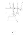
- Fig. 2 outlines the structure of a terminal 7 of the device 1 according to Fig. 1 in a two-line diagram, from which it is clear that the circuit breaker 9 separates the here only schematically reproduced connected string 2 all poles.
- the circuit breaker 9 is designed for twice the no-load voltage of the string 2, so that it is also able to switch off a string 2 connected to the device 1 with incorrect polarity, wherein the double open-circuit voltage is present across the contacts of the circuit breaker 9.
Priority Applications (9)
| Application Number | Priority Date | Filing Date | Title |
|---|---|---|---|
| EP20090167414 EP2282388A1 (fr) | 2009-08-06 | 2009-08-06 | Dispositif d'alimentation en énergie électrique d'une multitude de chaînes de modules photovoltaïques dans un réseau électrique |
| AU2010280736A AU2010280736A1 (en) | 2009-08-06 | 2010-08-03 | Device for supplying electrical energy from a plurality of strings of photovoltaic modules to a power grid |
| KR20127005751A KR20120055599A (ko) | 2009-08-06 | 2010-08-03 | 복수의 광전지모듈 스트링으로부터 전력계통으로의 전기에너지 공급용 장치 |
| CA2768521A CA2768521A1 (fr) | 2009-08-06 | 2010-08-03 | Dispositif destine a transmettre l'energie electrique d'une pluralite de chaines de modules photovoltaiques au reseau electrique |
| PCT/EP2010/061304 WO2011015587A2 (fr) | 2009-08-06 | 2010-08-03 | Dispositif destiné à transmettre lénergie électrique dune pluralité de chaînes de modules photovoltaïques au réseau électrique |
| CN2010800342511A CN102474097A (zh) | 2009-08-06 | 2010-08-03 | 用于向电网供应来自多个光伏模块串列的电能的设备 |
| EP10739620A EP2462672A2 (fr) | 2009-08-06 | 2010-08-03 | Dispositif d'alimentation en énergie électrique d'une multitude de chaînes de modules photovoltaïques dans un réseau électrique |
| JP2012523322A JP2013501497A (ja) | 2009-08-06 | 2010-08-03 | 複数のストリングの光起電モジュールから電力グリッドに電気エネルギーを供給するための装置 |
| US13/363,733 US20120126626A1 (en) | 2009-08-06 | 2012-02-01 | Device for supplying electrical energy from a plurality of strings of photovoltaic modules to a power grid |
Applications Claiming Priority (1)
| Application Number | Priority Date | Filing Date | Title |
|---|---|---|---|
| EP20090167414 EP2282388A1 (fr) | 2009-08-06 | 2009-08-06 | Dispositif d'alimentation en énergie électrique d'une multitude de chaînes de modules photovoltaïques dans un réseau électrique |
Publications (1)
| Publication Number | Publication Date |
|---|---|
| EP2282388A1 true EP2282388A1 (fr) | 2011-02-09 |
Family
ID=41478871
Family Applications (2)
| Application Number | Title | Priority Date | Filing Date |
|---|---|---|---|
| EP20090167414 Withdrawn EP2282388A1 (fr) | 2009-08-06 | 2009-08-06 | Dispositif d'alimentation en énergie électrique d'une multitude de chaînes de modules photovoltaïques dans un réseau électrique |
| EP10739620A Withdrawn EP2462672A2 (fr) | 2009-08-06 | 2010-08-03 | Dispositif d'alimentation en énergie électrique d'une multitude de chaînes de modules photovoltaïques dans un réseau électrique |
Family Applications After (1)
| Application Number | Title | Priority Date | Filing Date |
|---|---|---|---|
| EP10739620A Withdrawn EP2462672A2 (fr) | 2009-08-06 | 2010-08-03 | Dispositif d'alimentation en énergie électrique d'une multitude de chaînes de modules photovoltaïques dans un réseau électrique |
Country Status (8)
| Country | Link |
|---|---|
| US (1) | US20120126626A1 (fr) |
| EP (2) | EP2282388A1 (fr) |
| JP (1) | JP2013501497A (fr) |
| KR (1) | KR20120055599A (fr) |
| CN (1) | CN102474097A (fr) |
| AU (1) | AU2010280736A1 (fr) |
| CA (1) | CA2768521A1 (fr) |
| WO (1) | WO2011015587A2 (fr) |
Cited By (8)
| Publication number | Priority date | Publication date | Assignee | Title |
|---|---|---|---|---|
| EP2715928A2 (fr) * | 2011-06-03 | 2014-04-09 | Schneider Electric Solar Inverters USA, Inc. | Dispositif de commande de tension continue à dynamique élevée pour un onduleur photovoltaïque |
| DE102012112184A1 (de) | 2012-12-12 | 2014-06-12 | Sma Solar Technology Ag | Verfahren und Vorrichtung zum Schutz mehrerer Strings eines Photovoltaikgenerators vor Rückströmen |
| WO2014094929A1 (fr) | 2012-12-18 | 2014-06-26 | Ellenberger & Poensgen Gmbh | Procédé et dispositif de surveillance d'une installation photovoltaïque |
| EP2779350A1 (fr) * | 2013-03-15 | 2014-09-17 | General Electric Company | Système de transmission et de distribution de courant continu et son procédé de fonctionnement |
| CN104737406A (zh) * | 2012-10-23 | 2015-06-24 | 艾思玛太阳能技术股份公司 | 逆变器、用于操作逆变器的方法以及带有逆变器的供能系统 |
| DE102014115601B3 (de) * | 2014-10-27 | 2016-01-07 | Sma Solar Technology Ag | Combinerbox mit motorischer Überstromsicherung |
| CN106208129A (zh) * | 2016-06-21 | 2016-12-07 | 阳光电源股份有限公司 | 并联直流电源的接入控制方法及其应用的装置 |
| CN113904363A (zh) * | 2021-09-17 | 2022-01-07 | 科华数据股份有限公司 | 光储系统状态切换控制装置、光伏系统及控制方法 |
Families Citing this family (21)
| Publication number | Priority date | Publication date | Assignee | Title |
|---|---|---|---|---|
| US8779627B2 (en) | 2009-04-01 | 2014-07-15 | Nextronex, Inc. | Grid tie solar system and a method |
| DE102010055550A1 (de) * | 2010-12-22 | 2012-06-28 | Sma Solar Technology Ag | Wechselrichter, Energieerzeugungsanlage und Verfahren zum Betrieb einer Energieerzeugungsanlage |
| US9184594B2 (en) * | 2011-06-03 | 2015-11-10 | Schneider Electric Solar Inverters Usa, Inc. | Photovoltaic voltage regulation |
| DE102011107365A1 (de) * | 2011-06-29 | 2013-01-03 | eSYZz UG (haftungsbeschränkt) | Photovoltaik-Modul |
| DE102012104560B4 (de) * | 2012-05-25 | 2016-05-25 | Sma Solar Technology Ag | Erkennung der Stringkonfiguration für einen Multistring-Wechselrichter |
| DE202012007257U1 (de) * | 2012-07-26 | 2013-10-28 | Ellenberger & Poensgen Gmbh | Vorrichtung zum sicheren Schalten einer Photovoltaikanlage |
| DE102012214927A1 (de) | 2012-08-22 | 2014-02-27 | E.On Netz Gmbh | Verfahren zum Transport von Strom über ein vermaschtes Stromnetz |
| CN102798761B (zh) * | 2012-08-31 | 2015-01-07 | 阳光电源股份有限公司 | 一种对地绝缘阻抗检测方法、电路及具有该电路的设备 |
| US8648498B1 (en) * | 2012-11-19 | 2014-02-11 | Renewable Power Conversion, Inc | Photovoltaic power system with distributed photovoltaic string to polyphase AC power converters |
| US9105765B2 (en) * | 2012-12-18 | 2015-08-11 | Enphase Energy, Inc. | Smart junction box for a photovoltaic system |
| CN103631185B (zh) * | 2013-12-10 | 2016-01-20 | 浙江安德电器有限公司 | 自动断电节能电路 |
| CN107408820A (zh) | 2014-12-16 | 2017-11-28 | Abb瑞士股份有限公司 | 能量板布置功率耗散 |
| CN105827179B (zh) * | 2015-01-04 | 2018-09-07 | 华为技术有限公司 | 一种光伏系统 |
| CN107431097B (zh) | 2015-01-28 | 2020-02-14 | Abb瑞士股份有限公司 | 能量板布置关闭 |
| ES2832823T3 (es) | 2015-02-22 | 2021-06-11 | Marici Holdings The Netherlands Bv | Detección de polaridad inversa de cadenas fotovoltaicas |
| CN109239562B (zh) * | 2017-07-10 | 2022-08-09 | 比亚迪股份有限公司 | 列车以及列车的绝缘检测系统 |
| CN109239538B (zh) * | 2017-07-10 | 2022-08-09 | 比亚迪股份有限公司 | 列车以及列车的绝缘检测系统 |
| CN109239537B (zh) * | 2017-07-10 | 2022-08-09 | 比亚迪股份有限公司 | 列车以及列车的绝缘检测系统 |
| WO2021207880A1 (fr) * | 2020-04-13 | 2021-10-21 | 华为技术有限公司 | Appareil de protection contre les court-circuits, procédé de protection contre les court-circuits et système de génération d'énergie photovoltaïque |
| CN113252980A (zh) * | 2021-03-31 | 2021-08-13 | 华为技术有限公司 | 一种光储系统及对地绝缘阻抗检测方法 |
| CN113138326A (zh) * | 2021-05-12 | 2021-07-20 | 阳光电源股份有限公司 | 一种绝缘检测系统、绝缘检测方法及光伏系统 |
Citations (6)
| Publication number | Priority date | Publication date | Assignee | Title |
|---|---|---|---|---|
| JPH10201086A (ja) * | 1997-01-14 | 1998-07-31 | Nissin Electric Co Ltd | 太陽光発電装置 |
| JPH10285965A (ja) * | 1997-03-31 | 1998-10-23 | Meidensha Corp | 太陽光発電システム |
| US20060237058A1 (en) * | 2005-04-25 | 2006-10-26 | Mcclintock Ronald B | Direct current combiner box with power monitoring, ground fault detection and communications interface |
| WO2007048421A2 (fr) * | 2005-10-24 | 2007-05-03 | Conergy Ag | Interrupteur a fusibles avec gestion de commande pour piles solaires |
| US20070107767A1 (en) * | 2005-11-16 | 2007-05-17 | Arizona Public Service Company | DC power-generation system and integral control apparatus therefor |
| US20080123226A1 (en) * | 2006-11-24 | 2008-05-29 | Mcginn Patrick | Ground Fault Detector Interrupter |
Family Cites Families (10)
| Publication number | Priority date | Publication date | Assignee | Title |
|---|---|---|---|---|
| CA1118880A (fr) * | 1977-09-12 | 1982-02-23 | Peter Deacey | Circuit de commutation |
| JPH0779292B2 (ja) * | 1988-11-16 | 1995-08-23 | 愛知電子株式会社 | Catvシステム及び中継増幅器 |
| US4940903A (en) * | 1989-01-23 | 1990-07-10 | Square D Company | Motor controlled switch mechanism |
| JPH02285919A (ja) * | 1989-04-24 | 1990-11-26 | Toshiba Corp | ディジタルリレー装置 |
| US5341268A (en) * | 1991-12-16 | 1994-08-23 | Kabushiki Kaisha Toshiba | Method of and system for disconnecting faulty distribution line section from power distribution line |
| JPH07177652A (ja) * | 1993-12-17 | 1995-07-14 | Canon Inc | 太陽光発電システムおよび太陽光発電システムの保護方式 |
| JP2001275259A (ja) * | 2000-03-29 | 2001-10-05 | Canon Inc | 系統連系インバータおよび分散形発電システム |
| US6867958B2 (en) * | 2000-12-27 | 2005-03-15 | Abb Technology Ag | Loop restoration scheme for distribution feeders |
| JP2005168156A (ja) * | 2003-12-02 | 2005-06-23 | Mitsubishi Heavy Ind Ltd | 地絡対策装置及び発電システム |
| US20120050924A1 (en) * | 2010-08-24 | 2012-03-01 | Sanyo Electric Co., Ltd. | Current collecting box for photovoltaic power generation |
-
2009
- 2009-08-06 EP EP20090167414 patent/EP2282388A1/fr not_active Withdrawn
-
2010
- 2010-08-03 EP EP10739620A patent/EP2462672A2/fr not_active Withdrawn
- 2010-08-03 KR KR20127005751A patent/KR20120055599A/ko not_active Application Discontinuation
- 2010-08-03 JP JP2012523322A patent/JP2013501497A/ja active Pending
- 2010-08-03 AU AU2010280736A patent/AU2010280736A1/en not_active Abandoned
- 2010-08-03 WO PCT/EP2010/061304 patent/WO2011015587A2/fr active Application Filing
- 2010-08-03 CN CN2010800342511A patent/CN102474097A/zh active Pending
- 2010-08-03 CA CA2768521A patent/CA2768521A1/fr not_active Abandoned
-
2012
- 2012-02-01 US US13/363,733 patent/US20120126626A1/en not_active Abandoned
Patent Citations (6)
| Publication number | Priority date | Publication date | Assignee | Title |
|---|---|---|---|---|
| JPH10201086A (ja) * | 1997-01-14 | 1998-07-31 | Nissin Electric Co Ltd | 太陽光発電装置 |
| JPH10285965A (ja) * | 1997-03-31 | 1998-10-23 | Meidensha Corp | 太陽光発電システム |
| US20060237058A1 (en) * | 2005-04-25 | 2006-10-26 | Mcclintock Ronald B | Direct current combiner box with power monitoring, ground fault detection and communications interface |
| WO2007048421A2 (fr) * | 2005-10-24 | 2007-05-03 | Conergy Ag | Interrupteur a fusibles avec gestion de commande pour piles solaires |
| US20070107767A1 (en) * | 2005-11-16 | 2007-05-17 | Arizona Public Service Company | DC power-generation system and integral control apparatus therefor |
| US20080123226A1 (en) * | 2006-11-24 | 2008-05-29 | Mcginn Patrick | Ground Fault Detector Interrupter |
Cited By (20)
| Publication number | Priority date | Publication date | Assignee | Title |
|---|---|---|---|---|
| US9343906B2 (en) | 2011-06-03 | 2016-05-17 | Schneider Electric Solar Inverters Usa, Inc. | High dynamic DC-voltage controller for photovoltaic inverter |
| EP2715928A4 (fr) * | 2011-06-03 | 2014-12-03 | Schneider Electric Solar Inverters Usa Inc | Dispositif de commande de tension continue à dynamique élevée pour un onduleur photovoltaïque |
| EP2715928A2 (fr) * | 2011-06-03 | 2014-04-09 | Schneider Electric Solar Inverters USA, Inc. | Dispositif de commande de tension continue à dynamique élevée pour un onduleur photovoltaïque |
| CN104737406B (zh) * | 2012-10-23 | 2017-12-12 | 艾思玛太阳能技术股份公司 | 逆变器、用于操作逆变器的方法以及带有逆变器的供能系统 |
| CN104737406A (zh) * | 2012-10-23 | 2015-06-24 | 艾思玛太阳能技术股份公司 | 逆变器、用于操作逆变器的方法以及带有逆变器的供能系统 |
| US9806516B2 (en) | 2012-12-12 | 2017-10-31 | Sma Solar Technology Ag | Method and device for protecting several strings of a photovoltaic generator from reverse currents |
| DE102012112184A1 (de) | 2012-12-12 | 2014-06-12 | Sma Solar Technology Ag | Verfahren und Vorrichtung zum Schutz mehrerer Strings eines Photovoltaikgenerators vor Rückströmen |
| DE102012024728A1 (de) | 2012-12-18 | 2014-07-03 | Ellenberger & Poensgen Gmbh | Verfahren und Vorrichtung zur Überwachung einer elektrischen Anlage auf einen Rückstrom |
| WO2014094929A1 (fr) | 2012-12-18 | 2014-06-26 | Ellenberger & Poensgen Gmbh | Procédé et dispositif de surveillance d'une installation photovoltaïque |
| US9306391B2 (en) | 2013-03-15 | 2016-04-05 | General Electric Company | Direct current transmission and distribution system and method of operating the same |
| EP2779350A1 (fr) * | 2013-03-15 | 2014-09-17 | General Electric Company | Système de transmission et de distribution de courant continu et son procédé de fonctionnement |
| US10084303B2 (en) | 2014-10-27 | 2018-09-25 | Sma Solar Technology Ag | Combiner box having motorized overcurrent protection |
| WO2016066429A1 (fr) | 2014-10-27 | 2016-05-06 | Sma Solar Technology Ag | Boîtier multiplexeur comprenant un disjoncteur motorisé de courant de surcharge |
| DE102014115601B3 (de) * | 2014-10-27 | 2016-01-07 | Sma Solar Technology Ag | Combinerbox mit motorischer Überstromsicherung |
| CN106208129B (zh) * | 2016-06-21 | 2019-10-29 | 阳光电源股份有限公司 | 并联直流电源的接入控制方法及其应用的装置 |
| EP3264550A1 (fr) * | 2016-06-21 | 2018-01-03 | Sungrow Power Supply Co., Ltd. | Procédé de contrôle d'accès pour alimentations en courant direct parallèles et dispositif associé |
| CN106208129A (zh) * | 2016-06-21 | 2016-12-07 | 阳光电源股份有限公司 | 并联直流电源的接入控制方法及其应用的装置 |
| US10503126B2 (en) | 2016-06-21 | 2019-12-10 | Sungrow Power Supply Co., Ltd. | Access control method for parallel direct current power supplies and device thereof |
| CN113904363A (zh) * | 2021-09-17 | 2022-01-07 | 科华数据股份有限公司 | 光储系统状态切换控制装置、光伏系统及控制方法 |
| CN113904363B (zh) * | 2021-09-17 | 2023-08-18 | 科华数据股份有限公司 | 光储系统状态切换控制装置、光伏系统及控制方法 |
Also Published As
| Publication number | Publication date |
|---|---|
| US20120126626A1 (en) | 2012-05-24 |
| CA2768521A1 (fr) | 2011-02-10 |
| KR20120055599A (ko) | 2012-05-31 |
| WO2011015587A3 (fr) | 2011-06-16 |
| JP2013501497A (ja) | 2013-01-10 |
| EP2462672A2 (fr) | 2012-06-13 |
| WO2011015587A2 (fr) | 2011-02-10 |
| AU2010280736A1 (en) | 2012-01-19 |
| CN102474097A (zh) | 2012-05-23 |
Similar Documents
| Publication | Publication Date | Title |
|---|---|---|
| EP2282388A1 (fr) | Dispositif d'alimentation en énergie électrique d'une multitude de chaînes de modules photovoltaïques dans un réseau électrique | |
| EP2284973B1 (fr) | Capteur de flux de retour pour de modules solaire branché en parallèle | |
| EP2745327B1 (fr) | Boîte de connexions pour un panneau solaire, pourvue d'un circuit de protection | |
| EP3345301B1 (fr) | Système photovoltaïque sûr | |
| EP2726889B1 (fr) | Module photovoltaïque | |
| EP1841050B1 (fr) | Procédé pour convertir une tension continue en une tension triphasée | |
| EP3390133B1 (fr) | Module de sécurité et station de charge munie d'un module de sécurité | |
| EP2920858B1 (fr) | Procédé et dispositif pour protéger plusieurs branches d'un générateur photovoltaïque des courants de retour | |
| EP2296244A1 (fr) | Procédé et dispositif destinés à la connexion d'au moins une chaîne d'installation photovoltaïque et d'un onduleur | |
| EP2386870B1 (fr) | Procédé de test d'isolation pour grandes installations photovoltaïques | |
| DE102012109012B4 (de) | Schaltungsanordnung für ein Solarkraftwerk mit einer Gleichspannungsquelle für eine Offsetspannung | |
| EP3213407B1 (fr) | Boîtier multiplexeur comprenant un disjoncteur motorisé de courant de surcharge | |
| EP2499506A2 (fr) | Architecture d'appareil de commande de batterie | |
| EP2276137A2 (fr) | Installation photovoltaïque | |
| DE102008008505A1 (de) | PV-Teilgenerator-Anschlusskasten für eine PV-Anlage sowie PV-Anlage mit einer Vielzahl derartiger PV-Teilgenerator-Anschlusskästen | |
| DE102011083582A1 (de) | Stromverteiler für Kraftfahrzeug-Bordnetze | |
| EP1662264A1 (fr) | Dispositif destiné à la surveillance d'un réseau de distribution, en particulier d'un réseau de bord de véhicule automobile, et procédé destiné à la surveillance d'un tel réseau de distribution | |
| EP4200463B1 (fr) | Électrolyse alimentée par voie photovoltaïque | |
| DE102011075353A1 (de) | Fehlerüberwachungssystem für eine Verteilnetzstation eines Energieversorgungsnetzes | |
| DE202010008123U1 (de) | Umschalteinrichtung | |
| EP3259827A1 (fr) | Installation de remplacement de réseau, système de mise à la terre pour une installation de remplacement de réseau et procédé de fonctionnement | |
| DE102020210794B3 (de) | Batteriespeichervorrichtung, Parallelschaltung von Batteriespeichervorrichtungen und Verfahren zum Betreiben einer Batteriespeichervorrichtung | |
| EP2904677B1 (fr) | Circuiterie comprenant un onduleur | |
| DE102015115284B3 (de) | Schutzvorrichtung für eine elektrische Energieversorgungseinrichtung und elektrische Energieversorgungseinrichtung mit einer derartigen Schutzvorrichtung | |
| DE102006002245B4 (de) | Verfahren zur Überwachung eines abschaltbaren Kabels in einem elektrischen Netz, dafür geeignete Überwachungsvorrichtung sowie Überwachungssystem |
Legal Events
| Date | Code | Title | Description |
|---|---|---|---|
| PUAI | Public reference made under article 153(3) epc to a published international application that has entered the european phase |
Free format text: ORIGINAL CODE: 0009012 |
|
| AK | Designated contracting states |
Kind code of ref document: A1 Designated state(s): AT BE BG CH CY CZ DE DK EE ES FI FR GB GR HR HU IE IS IT LI LT LU LV MC MK MT NL NO PL PT RO SE SI SK SM TR |
|
| AX | Request for extension of the european patent |
Extension state: AL BA RS |
|
| STAA | Information on the status of an ep patent application or granted ep patent |
Free format text: STATUS: THE APPLICATION IS DEEMED TO BE WITHDRAWN |
|
| 18D | Application deemed to be withdrawn |
Effective date: 20110810 |