EP2282388A1 - Device for feeding in electrical energy of a number of strings of photovoltaic modules in an electricity network - Google Patents
Device for feeding in electrical energy of a number of strings of photovoltaic modules in an electricity network Download PDFInfo
- Publication number
- EP2282388A1 EP2282388A1 EP20090167414 EP09167414A EP2282388A1 EP 2282388 A1 EP2282388 A1 EP 2282388A1 EP 20090167414 EP20090167414 EP 20090167414 EP 09167414 A EP09167414 A EP 09167414A EP 2282388 A1 EP2282388 A1 EP 2282388A1
- Authority
- EP
- European Patent Office
- Prior art keywords
- string
- strings
- circuit breaker
- controller
- motor
- Prior art date
- Legal status (The legal status is an assumption and is not a legal conclusion. Google has not performed a legal analysis and makes no representation as to the accuracy of the status listed.)
- Withdrawn
Links
Images

Classifications
-
- H—ELECTRICITY
- H02—GENERATION; CONVERSION OR DISTRIBUTION OF ELECTRIC POWER
- H02H—EMERGENCY PROTECTIVE CIRCUIT ARRANGEMENTS
- H02H5/00—Emergency protective circuit arrangements for automatic disconnection directly responsive to an undesired change from normal non-electric working conditions with or without subsequent reconnection
-
- H—ELECTRICITY
- H02—GENERATION; CONVERSION OR DISTRIBUTION OF ELECTRIC POWER
- H02J—CIRCUIT ARRANGEMENTS OR SYSTEMS FOR SUPPLYING OR DISTRIBUTING ELECTRIC POWER; SYSTEMS FOR STORING ELECTRIC ENERGY
- H02J1/00—Circuit arrangements for dc mains or dc distribution networks
- H02J1/10—Parallel operation of dc sources
-
- G—PHYSICS
- G01—MEASURING; TESTING
- G01R—MEASURING ELECTRIC VARIABLES; MEASURING MAGNETIC VARIABLES
- G01R31/00—Arrangements for testing electric properties; Arrangements for locating electric faults; Arrangements for electrical testing characterised by what is being tested not provided for elsewhere
- G01R31/12—Testing dielectric strength or breakdown voltage ; Testing or monitoring effectiveness or level of insulation, e.g. of a cable or of an apparatus, for example using partial discharge measurements; Electrostatic testing
-
- H—ELECTRICITY
- H02—GENERATION; CONVERSION OR DISTRIBUTION OF ELECTRIC POWER
- H02J—CIRCUIT ARRANGEMENTS OR SYSTEMS FOR SUPPLYING OR DISTRIBUTING ELECTRIC POWER; SYSTEMS FOR STORING ELECTRIC ENERGY
- H02J3/00—Circuit arrangements for ac mains or ac distribution networks
- H02J3/36—Arrangements for transfer of electric power between ac networks via a high-tension dc link
-
- H—ELECTRICITY
- H02—GENERATION; CONVERSION OR DISTRIBUTION OF ELECTRIC POWER
- H02J—CIRCUIT ARRANGEMENTS OR SYSTEMS FOR SUPPLYING OR DISTRIBUTING ELECTRIC POWER; SYSTEMS FOR STORING ELECTRIC ENERGY
- H02J2300/00—Systems for supplying or distributing electric power characterised by decentralized, dispersed, or local generation
- H02J2300/20—The dispersed energy generation being of renewable origin
- H02J2300/22—The renewable source being solar energy
- H02J2300/24—The renewable source being solar energy of photovoltaic origin
-
- H—ELECTRICITY
- H02—GENERATION; CONVERSION OR DISTRIBUTION OF ELECTRIC POWER
- H02J—CIRCUIT ARRANGEMENTS OR SYSTEMS FOR SUPPLYING OR DISTRIBUTING ELECTRIC POWER; SYSTEMS FOR STORING ELECTRIC ENERGY
- H02J3/00—Circuit arrangements for ac mains or ac distribution networks
- H02J3/38—Arrangements for parallely feeding a single network by two or more generators, converters or transformers
- H02J3/381—Dispersed generators
-
- Y—GENERAL TAGGING OF NEW TECHNOLOGICAL DEVELOPMENTS; GENERAL TAGGING OF CROSS-SECTIONAL TECHNOLOGIES SPANNING OVER SEVERAL SECTIONS OF THE IPC; TECHNICAL SUBJECTS COVERED BY FORMER USPC CROSS-REFERENCE ART COLLECTIONS [XRACs] AND DIGESTS
- Y02—TECHNOLOGIES OR APPLICATIONS FOR MITIGATION OR ADAPTATION AGAINST CLIMATE CHANGE
- Y02E—REDUCTION OF GREENHOUSE GAS [GHG] EMISSIONS, RELATED TO ENERGY GENERATION, TRANSMISSION OR DISTRIBUTION
- Y02E10/00—Energy generation through renewable energy sources
- Y02E10/50—Photovoltaic [PV] energy
- Y02E10/56—Power conversion systems, e.g. maximum power point trackers
Definitions
- the invention relates to a device for feeding electrical energy from a plurality of strings of photovoltaic modules in a power grid having the features of independent claim 1.
- the individual strings that are connected to such a device usually not only consist of a series connection of photovoltaic modules, as the originally English word string suggests, but they regularly have several substrings that in the field, d. H. are summarized at or near the location of the photovoltaic modules in a parallel circuit.
- All parts of a device to which the present invention relates are summarized locally, i. H. centralized against the multitude of strings.
- all parts of the device are in a single central housing. But this is not necessarily the case. Rather, the device can also consist of individual modules, for which individual housings are provided. These individual housings are in the device but in one place and are not intended to be arranged in the field at the photovoltaic modules.
- a device to which the present invention relates serves to supply electrical energy to an AC network and has an inverter for this purpose.
- This inverter can be used in almost any way with boost converters, buck converters, converters (DC / DC converters and / or AC / AC converters) and transformers combined to match the output voltage of the inverter to the mains voltage of the AC mains.
- the present invention is concerned with the protection of the individual strings and the device for supplying electrical energy against errors, in particular insulation errors, in the region of the strings and their leads to the device.
- fuses are provided as overcurrent fuses in the apparatus for each of several connectable strings. Furthermore, a central DC load disconnect switch is provided for the current flowing from all strings. The monitoring of the individual substrings for failure is carried out by decentralized monitoring devices in the field. Of these, signal transmission paths to the central device, i. d. R. be provided by signal transmission lines. If a central device for detecting the isolation state of the plurality of strings detects an insulation fault, only the entire device can be stopped and / or central DC load break switches opened. If a string with incorrect polarity is connected to the known device, the associated fuse burns off, since the falling over her double open-circuit voltage from the fuse can not be switched in normal design.
- An apparatus having the features of the preamble of independent claim 1 is known in the form of a product of Siemens. Specifically, it is a 500 kW inverter, to which four strings with a power of 125 kW each are connected via separate fuse switch disconnectors and DC contactors and can thus be selectively switched on and off.
- a GFDI is provided as a central device for detecting the insulation state. This falls in a ground fault z. B. somewhere in the field of photovoltaic modules.
- the known device is then transferred to an isolated operation to avoid high ground currents.
- an automatic insulation measurement takes place in the field of photovoltaic modules. Once the error has been detected and assigned to a single string, the device will return to grounded the next day Operation whereby the DC contactor remains open to the string affected by the ground fault.
- the invention has for its object to provide a device with the features of the preamble of independent claim 1, which enables yield optimization with respect to the current fed into the grid while maintaining high reliability and low cost of the overall structure of a photovoltaic system using the device.
- the means for overcurrent protection and selective shutdown of the string provided in each terminal for each string comprise a circuit breaker which is motor-openable and closable.
- the respective string With this circuit breaker, the respective string is protected and it can be selectively switched on and off, if there is evidence of an error in the range of its substrings or leads to the device.
- these errors may be those registered by the central facility for detecting the isolation state of the plurality of strings. But it can also be about mistakes that are recognized in other ways.
- this detection preferably takes place in the new device only within the device. That is, no errors are detected in the field and communicated to the device, but the error detection takes place in the device, so that it requires no communication of these errors from the outside into the device.
- the leads from the individual strings to the new device must, since they are each intended to carry only a relatively small current, have no large cross-sections and can therefore be formed inexpensively and also easily installed.
- communication lines are saved, which are usually present parallel to the current-carrying connection lines.
- a controller of the new device can motor-drive the circuit breakers in the terminals of the plurality of strings in accordance with the isolation state detected by the isolation state detecting means.
- a reaction to an occurring insulation fault occurs immediately, d. H. the same day in the operation of the photovoltaic modules, with the aim to select the string that causes the insulation fault, and turn off this string by the associated circuit breaker is opened by a motor.
- the controller may first open all the circuit breakers by motor and then selectively close them again so as to assign the insulation fault, from which the central device can only detect its existence, to a single string.
- the re-closing of the circuit breaker can be done individually or according to known rapid selection method in variable groups.
- the means for overcurrent protection and for selectively switching off each string are constructed next to the circuit breaker from a current sensor.
- These current sensors make it possible to detect the failure of a substring of one of the strings by monitoring the currents flowing from the individual strings into the device, in particular when considering the collective of these currents, even if this string has a comparatively large number of parallel strings. Such monitoring may for example be based on how the current from the respective string behaves in relation to the currents from the other strings.
- the prerequisites for carrying out such a method are particularly good in the case of the new device, because a large number of comparison values are available here with the large number of strings, and thus statistical errors can be eliminated particularly well.
- each current sensor in the new device is direction-sensitive
- the case of a reverse current can also be ascertained, which indicates an error in the region of the string connected here or the reverse polarity of its connection to the new device. While a reverse polarity fault leads quickly to such a large current that the circuit breaker opens due to its integrated protection function, other errors that result in smaller back currents are only detected by the current sensor.
- the circuit breaker are designed at least for twice the open circuit voltage of the strings in the new device. This is relatively easy to implement and eliminates any burn-up in connection with polarity reversal errors.
- each circuit breaker turns off the associated string all poles, ie completely disconnects when the circuit breaker is opened. This is necessary in order to reliably switch off an insulation fault present in a string for the rest of the photovoltaic system.
- the new device for each string preferably only the connection for its power current leading leads is provided, i. H. no additional connection to any communication lines. There is also no wireless signal transmission in parallel with the power lines carrying power lines.
- the number of ports of the new device is typically at least 5, preferably at least 10, more preferably at least 20 and most preferably at least 30.
- the new device is therefore intended for a relatively large number of individual strings connected in parallel to the device ,
- the new device for use with strings each of which has at least 10, preferably at least 20, more preferably at least 40 and most preferably at least 50 partial strands. These are comparatively high numbers of substrings, considering that they are not monitored individually in the field. Rather, when using the new device, preferably all partial strings of a string are simply combined in the field, but here each partial string will normally be protected by an overcurrent fuse.
- Fig. 1 outlined a device 1 for feeding electrical energy from a plurality of strings 2 of solar modules 3 in a power grid 4, which is an AC network here.
- the dashed line in Fig. 1 limited device may be housed in a single housing.
- the components of the device 1 encompassed by the dashed line are provided in a central location and not distributed in the field in the field in the photovoltaic modules 3.
- Each string 2 comprises not only a series circuit of photovoltaic modules 3, but a plurality of such substrings 5, which are combined in the field under protection of the individual substrings 5, so that lead out of the field only current connecting leads 6 from each string 2 to the device 1.
- a connection 7 is provided on the device 1 for each string 2, to which only one string 2 is connected before the streams of all strings 2 are combined on a common bus line 8.
- a circuit breaker 9 is provided which can be opened and closed with a motor 10.
- the motor 10 is controlled by a module 11 of a controller of the device 1, which is assigned to the respective terminal 7.
- each circuit breaker 9 has an integrated mechanism which automatically opens the circuit breaker 9 in the event of an overcurrent exceeding a predetermined limit.
- a direction-sensitive current sensor 14 is provided in each terminal 7.
- the associated module 11 of the controller opens the circuit breaker 9 via the motor 10, even if the internal overcurrent fuse of the circuit breaker 9 still does not respond.
- the current sensors 14 are used in their total to monitor the strings 2 to a failure of individual substrings 5, including the Collectively, the currents flowing from the strings 2 and measured with the current sensors 14 are observed and analyzed. This takes place in a central module 12 of the control of the device 1.
- the device 1 has a device 15 for detecting the insulation state of the in Fig. 1 shown photovoltaic system 16 including the strings 2.
- this device 15 may be a GFDI, a so-called soft grounding device or a device for earth fault monitoring by measuring the insulation resistance.
- the device 15 If an insulation fault is registered by the device 15, this is reported to a module 13 of the control of the device 1. This module 13 can then stop a central inverter 17 of the device 1 or at least influence its operation until the insulation fault is located. If the isolation error lies in the region of one of the strings 2, it can be recognized by the fact that the controller 11 to 13 first opens all the power switches 9. Thereafter, the device 15, which must be reset if necessary in the case of a GFDI or a soft grounding device, may no longer indicate the insulation fault. Otherwise it is not in the area of strings 2, but elsewhere. If the insulation fault is no longer displayed, by selectively closing the circuit breaker 9 individually or in groups, the insulation fault can ultimately be assigned to a single string 2.
- This string 2 can then be sorted out by opening the associated circuit breaker 9, ie switched off and the rest of the strings 2 can further electrical energy without any adverse effects in the network 4 are fed.
- the device 1 can therefore return to the network 4 within a very short time in a proper operation under the supply of electrical energy.
- the losses caused by the failed string 2 remain low, in particular, when a comparatively large number of strings 2 are connected in parallel via a respective power switch 9 to the device 1.
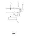
- Fig. 2 outlines the structure of a terminal 7 of the device 1 according to Fig. 1 in a two-line diagram, from which it is clear that the circuit breaker 9 separates the here only schematically reproduced connected string 2 all poles.
- the circuit breaker 9 is designed for twice the no-load voltage of the string 2, so that it is also able to switch off a string 2 connected to the device 1 with incorrect polarity, wherein the double open-circuit voltage is present across the contacts of the circuit breaker 9.
Landscapes
- Engineering & Computer Science (AREA)
- Power Engineering (AREA)
- Physics & Mathematics (AREA)
- General Physics & Mathematics (AREA)
- Photovoltaic Devices (AREA)
Abstract
Description
Die Erfindung bezieht sich auf eine Vorrichtung zur Einspeisung von elektrischer Energie von einer Vielzahl von Strings von Photovoltaikmodulen in ein Stromnetz mit den Merkmalen des unabhängigen Patentanspruchs 1.The invention relates to a device for feeding electrical energy from a plurality of strings of photovoltaic modules in a power grid having the features of
Die einzelnen Strings, die an eine solche Vorrichtung angeschlossen werden, bestehen üblicherweise nicht nur aus einer Reihenschaltung von Photovoltaikmodulen, wie dies der ursprünglich englischsprachige Begriff String nahelegt, sondern sie weisen regelmäßig mehrere Teilstrings auf, die im Feld, d. h. am oder nahe des Ortes der Photovoltaikmodule in einer Parallelschaltung zusammengefasst sind.The individual strings that are connected to such a device usually not only consist of a series connection of photovoltaic modules, as the originally English word string suggests, but they regularly have several substrings that in the field, d. H. are summarized at or near the location of the photovoltaic modules in a parallel circuit.
Alle Teile einer Vorrichtung, auf die sich die vorliegende Erfindung bezieht, sind örtlich zusammengefasst, d. h. gegenüber der Vielzahl von Strings zentralisiert. Üblicherweise befinden sich alle Teile der Vorrichtung in einem einzelnen zentralen Gehäuse. Dies ist aber nicht zwingend der Fall. Die Vorrichtung kann vielmehr auch aus einzelnen Modulen bestehen, für die einzelne Gehäuse vorgesehen sind. Auch diese einzelnen Gehäuse befinden sich bei der Vorrichtung aber an einem Ort und sind nicht zur Anordnung im Feld bei den Photovoltaikmodulen vorgesehen.All parts of a device to which the present invention relates are summarized locally, i. H. centralized against the multitude of strings. Usually, all parts of the device are in a single central housing. But this is not necessarily the case. Rather, the device can also consist of individual modules, for which individual housings are provided. These individual housings are in the device but in one place and are not intended to be arranged in the field at the photovoltaic modules.
Üblicherweise dient eine Vorrichtung, auf die sich die vorliegende Erfindung bezieht, zur Einspeisung von elektrischer Energie in ein Wechselstromnetz und weist hierzu einen Wechselrichter auf. Dieser Wechselrichter kann in nahezu beliebiger Weise mit Hochsetzstellern, Tiefsetzstellern, Umrichtern (DC/DC-Wandlern und/oder AC/AC-Wandlern) und Transformatoren kombiniert sein, um die Ausgangsspannung des Wechselrichters an die Netzspannung des Wechselstromnetzes anzupassen.Conventionally, a device to which the present invention relates serves to supply electrical energy to an AC network and has an inverter for this purpose. This inverter can be used in almost any way with boost converters, buck converters, converters (DC / DC converters and / or AC / AC converters) and transformers combined to match the output voltage of the inverter to the mains voltage of the AC mains.
Die vorliegende Erfindung befasst sich mit der Absicherung der einzelnen Strings und der Vorrichtung zur Einspeisung von elektrischer Energie gegenüber Fehlern, insbesondere Isolationsfehlern, im Bereich der Strings und deren Zuleitungen zu der Vorrichtung.The present invention is concerned with the protection of the individual strings and the device for supplying electrical energy against errors, in particular insulation errors, in the region of the strings and their leads to the device.
Bei einem aktuellen Produkt der Anmelderin, das zur Einspeisung von elektrischer Energie von einer Vielzahl von Strings von Photovoltaikmodulen in ein Stromnetz vorgesehen ist, sind in der Vorrichtung für jeden von mehreren anschließbaren Strings Schmelzsicherungen als Überstromsicherungen vorgesehen. Weiterhin ist ein zentraler Gleichstromlasttrennschalter für den von allen Strings fließenden Strom vorgesehen. Die Überwachung der einzelnen Teilstrings auf Ausfall erfolgt durch dezentrale Überwachungseinrichtungen im Feld. Von diesen müssen Signalübertragungswege zu der zentralen Vorrichtung, i. d. R. durch Signalübertragungsleitungen, bereitgestellt werden. Falls eine zentrale Einrichtung zur Erfassung des Isolationszustands der Vielzahl von Strings einen Isolationsfehler feststellt, kann nur die gesamte Vorrichtung angehalten und/oder zentrale Gleichstromlasttrennschalter geöffnet werden. Falls ein String mit falscher Polung an die bekannte Vorrichtung angeschlossen wird, brennt die zugehörige Schmelzsicherung ab, da die über ihr abfallende doppelte Leerlaufspannung von der Schmelzsicherung bei normaler Auslegung nicht geschaltet werden kann.In a recent Applicant's product, which is designed to feed electrical energy from a plurality of strings of photovoltaic modules into a power grid, fuses are provided as overcurrent fuses in the apparatus for each of several connectable strings. Furthermore, a central DC load disconnect switch is provided for the current flowing from all strings. The monitoring of the individual substrings for failure is carried out by decentralized monitoring devices in the field. Of these, signal transmission paths to the central device, i. d. R. be provided by signal transmission lines. If a central device for detecting the isolation state of the plurality of strings detects an insulation fault, only the entire device can be stopped and / or central DC load break switches opened. If a string with incorrect polarity is connected to the known device, the associated fuse burns off, since the falling over her double open-circuit voltage from the fuse can not be switched in normal design.
Eine Vorrichtung mit den Merkmalen des Oberbegriffs des unabhängigen Patentanspruchs 1 ist in Form eines Produkts der Firma Siemens bekannt. Konkret handelt es sich um einen 500 kW Wechselrichter, an den über separate Sicherungslasttrenner und Gleichstromschütze vier Strings mit einer Leistung von jeweils 125 kW angeschlossen sind und so gezielt an- und abgeschaltet werden können. Als zentrale Einrichtung zur Erfassung des Isolationszustands ist ein GFDI vorgesehen. Dieser fällt bei einem Erdschluss z. B. irgendwo im Feld der Photovoltaikmodule. Die bekannte Vorrichtung wird daraufhin in einen isolierten Betrieb überführt, um hohe Erdströme zu vermeiden. In der nächsten Nacht erfolgt eine automatische Isolationsmessung im Feld der Photovoltaikmodule. Sobald der Fehler festgestellt und einem einzelnen String zugeordnet ist, fährt die Vorrichtung am nächsten Tag wieder im geerdeten Betrieb, wobei der Gleichstromschütz zu dem von dem Erdungsfehler betroffenen String geöffnet bleibt.An apparatus having the features of the preamble of
Der Erfindung liegt die Aufgabe zugrunde, eine Vorrichtung mit den Merkmalen des Oberbegriffs des unabhängigen Patentanspruchs 1 aufzuzeigen, die eine Ertragsoptimierung hinsichtlich des in das Stromnetz eingespeisten Stroms bei gleichzeitig hoher Betriebssicherheit und günstigen Kosten des Gesamtaufbaus einer Photovoltaikanlage unter Verwendung der Vorrichtung ermöglicht.The invention has for its object to provide a device with the features of the preamble of
Erfindungsgemäß wird die Aufgabe durch eine Vorrichtung mit den Merkmalen des Patentanspruchs 1 gelöst. Bevorzugte Ausführungsformen der neuen Vorrichtung sind in den abhängigen Patentansprüchen definiert.According to the invention the object is achieved by a device having the features of
Bei der neuen Vorrichtung weisen die Mittel zur Überstromsicherung und zum selektiven Abschalten des Strings, die in jedem Anschluss für jeden String vorgesehen sind, einen Leistungsschalter auf, der motorisch öffenbar und schließbar ist. Mit diesem Leistungsschalter ist der jeweilige String abgesichert und er kann selektiv zu- und abgeschaltet werden, falls es Hinweise auf einen Fehler im Bereich seiner Teilstrings oder Zuleitungen zu der Vorrichtung gibt. Bei diesen Fehlern kann es sich insbesondere um solche handeln, die von der zentralen Einrichtung zur Erfassung des Isolationszustands der Vielzahl von Strings registriert werden. Es kann sich aber auch um Fehler handeln, die auf andere Weise erkannt werden. Vorzugsweise erfolgt diese Erkennung bei der neuen Vorrichtung aber ausschließlich innerhalb der Vorrichtung. Das heißt, es werden keine Fehler im Feld erkannt und an die Vorrichtung kommuniziert, sondern die Fehlererkennung erfolgt in der Vorrichtung, so dass es keiner Kommunikation dieser Fehler von außen in die Vorrichtung bedarf. Die Ausbildung der Mittel zur Überstromsicherung und zum selektiven Abschalten jedes Strings im Wesentlichen aus einem Leistungsschalter, der bei geringen Kosten nur eine begrenzte Stromtragfähigkeit aufweist, kann es nötig machen, den Strom und damit die Leistung auf eine vergleichsweise große Anzahl von Strings aufzuteilen, so dass jeder String nur den Strom liefert, der von einem Leistungsschalter getragen werden kann. Dies bedeutet zugleich, dass die Anzahl der Zuleitungen aus dem Feld entsprechend der Anzahl der Strings relativ groß sein kann. Die hiermit verbundenen Nachteile werden aber durch Vorteile der neuen Vorrichtung mehr als aufgewogen. Durch die größere Anzahl der Strings wirkt sich das Abschalten eines Strings über den zugehörigen Leistungsschalter beim Auftreten eines Fehlers in seinem Bereich auf die Gesamtleistung der jeweiligen Photovoltaikanlage relativ wenig aus. Die Zuleitungen von den einzelnen Strings zu der neuen Vorrichtung müssen, da sie jeweils nur einen relativ kleinen Strom führen sollen, keine großen Leitungsquerschnitte aufweisen und können von daher kostengünstig ausgebildet sein und auch einfach verlegt werden. Zudem werden bei der Verwendung der neuen Vorrichtung Kommunikationsleitungen eingespart, die üblicherweise parallel zu den stromführenden Anschlussleitungen vorhanden sind.In the new device, the means for overcurrent protection and selective shutdown of the string provided in each terminal for each string comprise a circuit breaker which is motor-openable and closable. With this circuit breaker, the respective string is protected and it can be selectively switched on and off, if there is evidence of an error in the range of its substrings or leads to the device. In particular, these errors may be those registered by the central facility for detecting the isolation state of the plurality of strings. But it can also be about mistakes that are recognized in other ways. However, this detection preferably takes place in the new device only within the device. That is, no errors are detected in the field and communicated to the device, but the error detection takes place in the device, so that it requires no communication of these errors from the outside into the device. The formation of the means for overcurrent protection and for selectively switching off each string substantially from a circuit breaker, which has only a limited current carrying capacity at low cost, can make it necessary, the current and thus the performance to a comparatively divide a large number of strings so that each string provides only the power that can be carried by a circuit breaker. This means at the same time that the number of leads from the field corresponding to the number of strings can be relatively large. The disadvantages associated with this are more than offset by the advantages of the new device. Due to the greater number of strings, switching off a string via the associated circuit breaker when a fault occurs in its area has a relatively small effect on the overall performance of the respective photovoltaic system. The leads from the individual strings to the new device must, since they are each intended to carry only a relatively small current, have no large cross-sections and can therefore be formed inexpensively and also easily installed. In addition, when using the new device, communication lines are saved, which are usually present parallel to the current-carrying connection lines.
Konkret kann eine Steuerung der neuen Vorrichtung die Leistungsschalter in den Anschlüssen der Vielzahl der Strings abhängig von der Einrichtung zur Erfassung des Isolationszustands erfassten Isolationszustand motorisch ansteuern. Dabei erfolgt erfindungsgemäß eine Reaktion auf einen auftretenden Isolationsfehler sofort, d. h. noch am selben Tag im Betrieb der Photovoltaikmodule, mit dem Ziel, den String zu selektieren, der den Isolationsfehler verursacht, und diesen String abzuschalten, indem der zugehörige Leistungsschalter motorisch geöffnet wird.Concretely, a controller of the new device can motor-drive the circuit breakers in the terminals of the plurality of strings in accordance with the isolation state detected by the isolation state detecting means. In this case, according to the invention, a reaction to an occurring insulation fault occurs immediately, d. H. the same day in the operation of the photovoltaic modules, with the aim to select the string that causes the insulation fault, and turn off this string by the associated circuit breaker is opened by a motor.
Zu dem genannten Zweck kann die Steuerung beim Auftreten eines Isolationsfehlers zunächst alle Leistungsschalter motorisch öffnen und dann selektiv wieder schließen, um den Isolationsfehler, von dem die zentrale Einrichtung nur seine Existenz erkennen kann, einem einzelnen String zuzuordnen. Dabei kann das Wiederschließen der Leistungsschalter einzeln oder auch nach bekannten schnellen Selektionsverfahren in variablen Gruppen erfolgen.For the stated purpose, when an insulation fault occurs, the controller may first open all the circuit breakers by motor and then selectively close them again so as to assign the insulation fault, from which the central device can only detect its existence, to a single string. The re-closing of the circuit breaker can be done individually or according to known rapid selection method in variable groups.
Je nach Aufbau der zentralen Einrichtung zur Erfassung des Isolationszustands, z. B. als GFDI, Soft Grounding-Einrichtung oder als Gerät zur Erdschlussüberwachung mittels Messung des Isolationswiderstands, kann es erforderlich sein, dass die Steuerung der neuen Vorrichtung diese Einrichtung vor dem motorischen Wiederschließen aller Leistungsschalter zurücksetzt, um sie in die Lage zu versetzen, einen neuerlichen Isolationsfehler zu erkennen. Dasselbe gilt bei diesen Einrichtungen zur Erfassung des Isolationszustands, wenn ein Isolationsfehler im Folgenden einer Gruppe von Strings zugeordnet wurde, weil er beim Schließen der entsprechenden Leistungsschalter wieder aufgetreten ist und eine weitere Selektion des fehlerbehafteten Strings erfolgen soll.Depending on the structure of the central device for detecting the insulation state, z. B. as GFDI, soft grounding device or as a device for ground fault monitoring by measuring the insulation resistance, it may be necessary that the control of the new device resets this device prior to the motor re-closing all circuit breakers to enable them, a renewed Isolation error to recognize. The same applies to these devices for detecting the insulation state, if an isolation error has subsequently been assigned to a group of strings, because when closing the isolation state corresponding circuit breaker has occurred again and a further selection of the faulty string is to take place.
Besonders bevorzugt ist es bei der neuen Vorrichtung, wenn die Mittel zur Überstromsicherung und zum selektiven Abschalten jedes Strings neben dem Leistungsschalter aus einem Stromsensor aufgebaut sind. Diese Stromsensoren ermöglichen es durch Überwachung der von den einzelnen Strings in die Vorrichtung fließenden Ströme, insbesondere bei Betrachtung des Kollektivs dieser Ströme, den Ausfall eines Teilstrings eines der Strings zu erkennen, auch wenn dieser String eine vergleichweise große Anzahl von parallel geschalteten Teilstrings aufweist. Eine derartige Überwachung kann beispielsweise darauf basieren, wie sich der Strom von dem jeweiligen String im Vergleich zu den Strömen von den anderen Strings verhält. Die Voraussetzungen für die Durchführung eines solchen Verfahrens sind bei der neuen Vorrichtung besonders gut, weil hier mit der großen Anzahl der Strings eine große Anzahl an Vergleichswerten zur Verfügung steht und damit statistische Fehler besonders gut eliminiert werden können.It is particularly preferred in the new device, when the means for overcurrent protection and for selectively switching off each string are constructed next to the circuit breaker from a current sensor. These current sensors make it possible to detect the failure of a substring of one of the strings by monitoring the currents flowing from the individual strings into the device, in particular when considering the collective of these currents, even if this string has a comparatively large number of parallel strings. Such monitoring may for example be based on how the current from the respective string behaves in relation to the currents from the other strings. The prerequisites for carrying out such a method are particularly good in the case of the new device, because a large number of comparison values are available here with the large number of strings, and thus statistical errors can be eliminated particularly well.
Zusätzlich kann dadurch, dass jeder Stromsensor bei der neuen Vorrichtung richtungssensitiv ist, auch der Fall eines Rückstroms festgestellt werden, der auf einen Fehler im Bereich des hier angeschlossenen Strings oder der Verpolung seines Anschlusses an die neue Vorrichtung hinweist. Während ein Verpolungsfehler schnell zu einem so großen Strom führt, dass der Leistungsschalter aufgrund seiner integrierten Schutzfunktion öffnet, werden andere Fehler, die zu kleineren Rückströmen führen, nur durch den Stromsensor erkannt.In addition, by virtue of the fact that each current sensor in the new device is direction-sensitive, the case of a reverse current can also be ascertained, which indicates an error in the region of the string connected here or the reverse polarity of its connection to the new device. While a reverse polarity fault leads quickly to such a large current that the circuit breaker opens due to its integrated protection function, other errors that result in smaller back currents are only detected by the current sensor.
Um einen Verpolungsfehler sicher abzufangen, sind bei der neuen Vorrichtung die Leistungsschalter zumindest für die doppelte Leerlaufspannung der Strings ausgelegt. Dies ist vergleichsweise einfach zu realisieren und beseitigt jede Abbrandgefahr im Zusammenhang mit Verpolungsfehlern.To intercept a reverse polarity error safely, the circuit breaker are designed at least for twice the open circuit voltage of the strings in the new device. This is relatively easy to implement and eliminates any burn-up in connection with polarity reversal errors.
Weiter ist es bei der neuen Vorrichtung bevorzugt, dass jeder Leistungsschalter den zugehörigen String allpolig abschaltet, d. h. vollständig abtrennt, wenn der Leistungsschalter geöffnet wird. Dies ist erforderlich, um einen in einem String vorhandenen Isolationsfehler für die restliche Photovoltaikanlage zuverlässig auszuschalten.Further, it is preferred in the new device that each circuit breaker turns off the associated string all poles, ie completely disconnects when the circuit breaker is opened. This is necessary in order to reliably switch off an insulation fault present in a string for the rest of the photovoltaic system.
Wie bereits angedeutet wurde, ist bei der neuen Vorrichtung für jeden String vorzugsweise nur der Anschluss für seine Leistungsstrom führenden Anschlussleitungen vorgesehen, d. h. kein zusätzlicher Anschluss zu irgendwelchen Kommunikationsleitungen. Es gibt auch keine drahtlose Signalübertragung parallel zu den den Leistungsstrom führenden Anschlussleitungen.As already indicated, in the new device for each string, preferably only the connection for its power current leading leads is provided, i. H. no additional connection to any communication lines. There is also no wireless signal transmission in parallel with the power lines carrying power lines.
Die Anzahl der Anschlüsse der neuen Vorrichtung beträgt typischerweise mindestens 5, vorzugsweise mindestens 10, mehr bevorzugt mindestens 20 und am meisten bevorzugt mindestens 30. Die neue Vorrichtung ist daher für eine relativ große Anzahl von einzelnen Strings vorgesehen, die parallel zueinander an die Vorrichtung angeschlossen werden.The number of ports of the new device is typically at least 5, preferably at least 10, more preferably at least 20 and most preferably at least 30. The new device is therefore intended for a relatively large number of individual strings connected in parallel to the device ,
Besonders geeignet ist die neue Vorrichtung zur Verwendung mit Strings, von denen jeder einzelne String mindestens 10, vorzugsweise mindestens 20, mehr bevorzugt mindestens 40 und am meisten bevorzugt mindestens 50 Teilstrings aufweist. Dies sind vergleichsweise hohe Anzahlen von Teilstrings, wenn man berücksichtigt, dass diese nicht einzeln im Feld überwacht werden. Vielmehr sind bei der Verwendung der neuen Vorrichtung vorzugsweise alle Teilstrings eines Strings im Feld einfach zusammengeschlossen, wobei hier jedoch jeder Teilstring normalerweise durch eine Überstromsicherung abgesichert sein wird.Particularly suitable is the new device for use with strings, each of which has at least 10, preferably at least 20, more preferably at least 40 and most preferably at least 50 partial strands. These are comparatively high numbers of substrings, considering that they are not monitored individually in the field. Rather, when using the new device, preferably all partial strings of a string are simply combined in the field, but here each partial string will normally be protected by an overcurrent fuse.
Vorteilhafte Weiterbildungen der Erfindung ergeben sich aus den Patentansprüchen, der Beschreibung und den Zeichnungen. Die in der Beschreibungseinleitung genannten Vorteile von Merkmalen und von Kombinationen mehrerer Merkmale sind lediglich beispielhaft und können alternativ oder kumulativ zur Wirkung kommen, ohne dass die Vorteile zwingend von erfindungsgemäßen Ausführungsformen erzielt werden müssen. Weitere Merkmale sind den Zeichnungen - insbesondere den dargestellten Geometrien und den relativen Abmessungen mehrerer Bauteile zueinander sowie deren relativer Anordnung und Wirkverbindung - zu entnehmen. Die Kombination von Merkmalen unterschiedlicher Ausführungsformen der Erfindung oder von Merkmalen unterschiedlicher Patentansprüche ist ebenfalls abweichend von den gewählten Rückbeziehungen der Patentansprüche möglich und wird hiermit angeregt. Dies betrifft auch solche Merkmale, die in separaten Zeichnungen dargestellt sind oder bei deren Beschreibung genannt werden. Diese Merkmale können auch mit Merkmalen unterschiedlicher Patentansprüche kombiniert werden. Ebenso können in den Patentansprüchen aufgeführte Merkmale für weitere Ausführungsformen der Erfindung entfallen.Advantageous developments of the invention will become apparent from the claims, the description and the drawings. The advantages of features and of combinations of several features mentioned in the introduction to the description are merely exemplary and can come into effect alternatively or cumulatively, without the advantages having to be achieved by embodiments according to the invention. Further features are the drawings - in particular the illustrated geometries and the relative dimensions of several components to each other and their relative arrangement and operative connection - refer. The combination of features of different embodiments of the invention or of features of different claims is also possible deviating from the chosen relationships of the claims and is hereby stimulated. This also applies to those features which are shown in separate drawings or are mentioned in their description. These features can also be combined with features of different claims. Likewise, in the claims listed features for further embodiments of the invention can be omitted.
Die Erfindung wird im Folgenden anhand eines Ausführungsbeispiels unter Bezugnahe auf die beigefügten Zeichnungen näher erläutert und beschrieben.
- Fig. 1
- zeigt die neue Vorrichtung in einem schematischen Einlinienschaubild und
- Fig. 2
- skizziert detaillierter den Aufbau eines Anschlusses der Vorrichtung 1 für einen String.
- Fig. 1
- shows the new device in a schematic single-line diagram and
- Fig. 2
- outlined in more detail the structure of a connection of the
device 1 for a string.
- 11
- Vorrichtungcontraption
- 22
- Stringstring
- 33
- Photovoltaikmodulphotovoltaic module
- 44
- Stromnetzpower grid
- 55
- Teilstringsubstring
- 66
- Anschlussleitungconnecting cable
- 77
- Anschlussconnection
- 88th
- Busleitungbus line
- 99
- Leistungsschalterbreakers
- 1010
- Motorengine
- 1111
- Modul der SteuerungModule of the controller
- 1212
- Modul der SteuerungModule of the controller
- 1313
- Modul der SteuerungModule of the controller
- 1414
- Stromsensorcurrent sensor
- 1515
- Einrichtung zur Erfassung des IsolationszustandsDevice for detecting the state of isolation
- 1616
- Photovoltaikanlagephotovoltaic system
- 1717
- Wechselrichterinverter
Claims (15)
Priority Applications (9)
| Application Number | Priority Date | Filing Date | Title |
|---|---|---|---|
| EP20090167414 EP2282388A1 (en) | 2009-08-06 | 2009-08-06 | Device for feeding in electrical energy of a number of strings of photovoltaic modules in an electricity network |
| CN2010800342511A CN102474097A (en) | 2009-08-06 | 2010-08-03 | Device for supplying electrical energy from a plurality of strings of photovoltaic modules to a power grid |
| CA2768521A CA2768521A1 (en) | 2009-08-06 | 2010-08-03 | Device for supplying electrical energy from a plurality of strings of photovoltaic modules to a power grid |
| JP2012523322A JP2013501497A (en) | 2009-08-06 | 2010-08-03 | Apparatus for supplying electrical energy to a power grid from a multi-string photovoltaic module |
| AU2010280736A AU2010280736A1 (en) | 2009-08-06 | 2010-08-03 | Device for supplying electrical energy from a plurality of strings of photovoltaic modules to a power grid |
| PCT/EP2010/061304 WO2011015587A2 (en) | 2009-08-06 | 2010-08-03 | Device for supplying electrical energy from a plurality of strings of photovoltaic modules to a power grid |
| EP10739620A EP2462672A2 (en) | 2009-08-06 | 2010-08-03 | Device for supplying electrical energy from a plurality of strings of photovoltaic modules to a power grid |
| KR20127005751A KR20120055599A (en) | 2009-08-06 | 2010-08-03 | Device for supplying electrical energy from a plurality of strings of photovoltaic modules to a power grid |
| US13/363,733 US20120126626A1 (en) | 2009-08-06 | 2012-02-01 | Device for supplying electrical energy from a plurality of strings of photovoltaic modules to a power grid |
Applications Claiming Priority (1)
| Application Number | Priority Date | Filing Date | Title |
|---|---|---|---|
| EP20090167414 EP2282388A1 (en) | 2009-08-06 | 2009-08-06 | Device for feeding in electrical energy of a number of strings of photovoltaic modules in an electricity network |
Publications (1)
| Publication Number | Publication Date |
|---|---|
| EP2282388A1 true EP2282388A1 (en) | 2011-02-09 |
Family
ID=41478871
Family Applications (2)
| Application Number | Title | Priority Date | Filing Date |
|---|---|---|---|
| EP20090167414 Withdrawn EP2282388A1 (en) | 2009-08-06 | 2009-08-06 | Device for feeding in electrical energy of a number of strings of photovoltaic modules in an electricity network |
| EP10739620A Withdrawn EP2462672A2 (en) | 2009-08-06 | 2010-08-03 | Device for supplying electrical energy from a plurality of strings of photovoltaic modules to a power grid |
Family Applications After (1)
| Application Number | Title | Priority Date | Filing Date |
|---|---|---|---|
| EP10739620A Withdrawn EP2462672A2 (en) | 2009-08-06 | 2010-08-03 | Device for supplying electrical energy from a plurality of strings of photovoltaic modules to a power grid |
Country Status (8)
| Country | Link |
|---|---|
| US (1) | US20120126626A1 (en) |
| EP (2) | EP2282388A1 (en) |
| JP (1) | JP2013501497A (en) |
| KR (1) | KR20120055599A (en) |
| CN (1) | CN102474097A (en) |
| AU (1) | AU2010280736A1 (en) |
| CA (1) | CA2768521A1 (en) |
| WO (1) | WO2011015587A2 (en) |
Cited By (8)
| Publication number | Priority date | Publication date | Assignee | Title |
|---|---|---|---|---|
| EP2715928A2 (en) * | 2011-06-03 | 2014-04-09 | Schneider Electric Solar Inverters USA, Inc. | High dynamic dc-voltage controller for photovoltaic inverter |
| DE102012112184A1 (en) | 2012-12-12 | 2014-06-12 | Sma Solar Technology Ag | Method and device for protecting multiple strings of a photovoltaic generator from backflow |
| WO2014094929A1 (en) | 2012-12-18 | 2014-06-26 | Ellenberger & Poensgen Gmbh | Method and device for monitoring a photovoltaic system |
| EP2779350A1 (en) * | 2013-03-15 | 2014-09-17 | General Electric Company | Direct current transmission and distribution system and method of operating the same |
| CN104737406A (en) * | 2012-10-23 | 2015-06-24 | 艾思玛太阳能技术股份公司 | Inverter, method for operating an inverter and energy supply installation with an inverter |
| DE102014115601B3 (en) * | 2014-10-27 | 2016-01-07 | Sma Solar Technology Ag | Combinerbox with motor overcurrent protection |
| CN106208129A (en) * | 2016-06-21 | 2016-12-07 | 阳光电源股份有限公司 | The connection control method of parallel connection direct power supply and the device of application thereof |
| CN113904363A (en) * | 2021-09-17 | 2022-01-07 | 科华数据股份有限公司 | Light storage system state switching control device, photovoltaic system and control method |
Families Citing this family (22)
| Publication number | Priority date | Publication date | Assignee | Title |
|---|---|---|---|---|
| US8779627B2 (en) | 2009-04-01 | 2014-07-15 | Nextronex, Inc. | Grid tie solar system and a method |
| DE102010055550A1 (en) * | 2010-12-22 | 2012-06-28 | Sma Solar Technology Ag | Inverter, power plant and method of operating a power plant |
| US9184594B2 (en) * | 2011-06-03 | 2015-11-10 | Schneider Electric Solar Inverters Usa, Inc. | Photovoltaic voltage regulation |
| DE102011107365A1 (en) * | 2011-06-29 | 2013-01-03 | eSYZz UG (haftungsbeschränkt) | Photovoltaic module |
| DE102012104560B4 (en) * | 2012-05-25 | 2016-05-25 | Sma Solar Technology Ag | Detecting the string configuration for a multi-string inverter |
| DE202012007257U1 (en) * | 2012-07-26 | 2013-10-28 | Ellenberger & Poensgen Gmbh | Device for safely switching a photovoltaic system |
| DE102012214927A1 (en) | 2012-08-22 | 2014-02-27 | E.On Netz Gmbh | Method of transporting electricity over a meshed power grid |
| CN102798761B (en) * | 2012-08-31 | 2015-01-07 | 阳光电源股份有限公司 | Ground insulation impedance detection method, circuit and equipment with circuit |
| US8648498B1 (en) * | 2012-11-19 | 2014-02-11 | Renewable Power Conversion, Inc | Photovoltaic power system with distributed photovoltaic string to polyphase AC power converters |
| US9105765B2 (en) | 2012-12-18 | 2015-08-11 | Enphase Energy, Inc. | Smart junction box for a photovoltaic system |
| CN103631185B (en) * | 2013-12-10 | 2016-01-20 | 浙江安德电器有限公司 | Auto-power-off energy-saving circuit |
| US10097108B2 (en) | 2014-12-16 | 2018-10-09 | Abb Schweiz Ag | Energy panel arrangement power dissipation |
| CN105827179B (en) * | 2015-01-04 | 2018-09-07 | 华为技术有限公司 | A kind of photovoltaic system |
| US10348094B2 (en) | 2015-01-28 | 2019-07-09 | Abb Schweiz Ag | Energy panel arrangement shutdown |
| AU2016219770A1 (en) | 2015-02-22 | 2017-09-07 | Abb Schweiz Ag | Photovoltaic string reverse polarity detection |
| CN109239538B (en) * | 2017-07-10 | 2022-08-09 | 比亚迪股份有限公司 | Train and insulation detection system of train |
| CN109239537B (en) * | 2017-07-10 | 2022-08-09 | 比亚迪股份有限公司 | Train and insulation detection system of train |
| CN109239562B (en) * | 2017-07-10 | 2022-08-09 | 比亚迪股份有限公司 | Train and insulation detection system of train |
| WO2021207880A1 (en) * | 2020-04-13 | 2021-10-21 | 华为技术有限公司 | Short circuit protection apparatus, short circuit protection method, and photovoltaic power generation system |
| CN113252980A (en) * | 2021-03-31 | 2021-08-13 | 华为技术有限公司 | Optical storage system and ground insulation impedance detection method |
| CN113138326B (en) * | 2021-05-12 | 2024-05-14 | 阳光电源股份有限公司 | Insulation detection system, insulation detection method and photovoltaic system |
| US12088247B2 (en) | 2022-05-20 | 2024-09-10 | Inergy Holdings, Llc. | Modular photovoltaic power production system |
Citations (6)
| Publication number | Priority date | Publication date | Assignee | Title |
|---|---|---|---|---|
| JPH10201086A (en) * | 1997-01-14 | 1998-07-31 | Nissin Electric Co Ltd | Solar beam power generation system |
| JPH10285965A (en) * | 1997-03-31 | 1998-10-23 | Meidensha Corp | Photovoltaic power generation system |
| US20060237058A1 (en) * | 2005-04-25 | 2006-10-26 | Mcclintock Ronald B | Direct current combiner box with power monitoring, ground fault detection and communications interface |
| WO2007048421A2 (en) * | 2005-10-24 | 2007-05-03 | Conergy Ag | Switch-fuse with control management for solar cells |
| US20070107767A1 (en) * | 2005-11-16 | 2007-05-17 | Arizona Public Service Company | DC power-generation system and integral control apparatus therefor |
| US20080123226A1 (en) * | 2006-11-24 | 2008-05-29 | Mcginn Patrick | Ground Fault Detector Interrupter |
Family Cites Families (10)
| Publication number | Priority date | Publication date | Assignee | Title |
|---|---|---|---|---|
| CA1118880A (en) * | 1977-09-12 | 1982-02-23 | Peter Deacey | Power switching circuit |
| JPH0779292B2 (en) * | 1988-11-16 | 1995-08-23 | 愛知電子株式会社 | CATV system and relay amplifier |
| US4940903A (en) * | 1989-01-23 | 1990-07-10 | Square D Company | Motor controlled switch mechanism |
| JPH02285919A (en) * | 1989-04-24 | 1990-11-26 | Toshiba Corp | Digital relay device |
| US5341268A (en) * | 1991-12-16 | 1994-08-23 | Kabushiki Kaisha Toshiba | Method of and system for disconnecting faulty distribution line section from power distribution line |
| JPH07177652A (en) * | 1993-12-17 | 1995-07-14 | Canon Inc | Solar beam power generation system and protective system therefor |
| JP2001275259A (en) * | 2000-03-29 | 2001-10-05 | Canon Inc | Linked system inverter and distributed power generation system |
| US6867958B2 (en) * | 2000-12-27 | 2005-03-15 | Abb Technology Ag | Loop restoration scheme for distribution feeders |
| JP2005168156A (en) * | 2003-12-02 | 2005-06-23 | Mitsubishi Heavy Ind Ltd | Ground fault countermeasure device and power generating system |
| US20120050924A1 (en) * | 2010-08-24 | 2012-03-01 | Sanyo Electric Co., Ltd. | Current collecting box for photovoltaic power generation |
-
2009
- 2009-08-06 EP EP20090167414 patent/EP2282388A1/en not_active Withdrawn
-
2010
- 2010-08-03 EP EP10739620A patent/EP2462672A2/en not_active Withdrawn
- 2010-08-03 AU AU2010280736A patent/AU2010280736A1/en not_active Abandoned
- 2010-08-03 CA CA2768521A patent/CA2768521A1/en not_active Abandoned
- 2010-08-03 WO PCT/EP2010/061304 patent/WO2011015587A2/en active Application Filing
- 2010-08-03 KR KR20127005751A patent/KR20120055599A/en not_active Application Discontinuation
- 2010-08-03 JP JP2012523322A patent/JP2013501497A/en active Pending
- 2010-08-03 CN CN2010800342511A patent/CN102474097A/en active Pending
-
2012
- 2012-02-01 US US13/363,733 patent/US20120126626A1/en not_active Abandoned
Patent Citations (6)
| Publication number | Priority date | Publication date | Assignee | Title |
|---|---|---|---|---|
| JPH10201086A (en) * | 1997-01-14 | 1998-07-31 | Nissin Electric Co Ltd | Solar beam power generation system |
| JPH10285965A (en) * | 1997-03-31 | 1998-10-23 | Meidensha Corp | Photovoltaic power generation system |
| US20060237058A1 (en) * | 2005-04-25 | 2006-10-26 | Mcclintock Ronald B | Direct current combiner box with power monitoring, ground fault detection and communications interface |
| WO2007048421A2 (en) * | 2005-10-24 | 2007-05-03 | Conergy Ag | Switch-fuse with control management for solar cells |
| US20070107767A1 (en) * | 2005-11-16 | 2007-05-17 | Arizona Public Service Company | DC power-generation system and integral control apparatus therefor |
| US20080123226A1 (en) * | 2006-11-24 | 2008-05-29 | Mcginn Patrick | Ground Fault Detector Interrupter |
Cited By (20)
| Publication number | Priority date | Publication date | Assignee | Title |
|---|---|---|---|---|
| US9343906B2 (en) | 2011-06-03 | 2016-05-17 | Schneider Electric Solar Inverters Usa, Inc. | High dynamic DC-voltage controller for photovoltaic inverter |
| EP2715928A4 (en) * | 2011-06-03 | 2014-12-03 | Schneider Electric Solar Inverters Usa Inc | High dynamic dc-voltage controller for photovoltaic inverter |
| EP2715928A2 (en) * | 2011-06-03 | 2014-04-09 | Schneider Electric Solar Inverters USA, Inc. | High dynamic dc-voltage controller for photovoltaic inverter |
| CN104737406B (en) * | 2012-10-23 | 2017-12-12 | 艾思玛太阳能技术股份公司 | Inverter, the method for operating inverter and the energy supplying system with inverter |
| CN104737406A (en) * | 2012-10-23 | 2015-06-24 | 艾思玛太阳能技术股份公司 | Inverter, method for operating an inverter and energy supply installation with an inverter |
| US9806516B2 (en) | 2012-12-12 | 2017-10-31 | Sma Solar Technology Ag | Method and device for protecting several strings of a photovoltaic generator from reverse currents |
| DE102012112184A1 (en) | 2012-12-12 | 2014-06-12 | Sma Solar Technology Ag | Method and device for protecting multiple strings of a photovoltaic generator from backflow |
| DE102012024728A1 (en) | 2012-12-18 | 2014-07-03 | Ellenberger & Poensgen Gmbh | Method and device for monitoring an electrical system for a return current |
| WO2014094929A1 (en) | 2012-12-18 | 2014-06-26 | Ellenberger & Poensgen Gmbh | Method and device for monitoring a photovoltaic system |
| US9306391B2 (en) | 2013-03-15 | 2016-04-05 | General Electric Company | Direct current transmission and distribution system and method of operating the same |
| EP2779350A1 (en) * | 2013-03-15 | 2014-09-17 | General Electric Company | Direct current transmission and distribution system and method of operating the same |
| US10084303B2 (en) | 2014-10-27 | 2018-09-25 | Sma Solar Technology Ag | Combiner box having motorized overcurrent protection |
| WO2016066429A1 (en) | 2014-10-27 | 2016-05-06 | Sma Solar Technology Ag | Combiner box having motorized overcurrent protection |
| DE102014115601B3 (en) * | 2014-10-27 | 2016-01-07 | Sma Solar Technology Ag | Combinerbox with motor overcurrent protection |
| CN106208129B (en) * | 2016-06-21 | 2019-10-29 | 阳光电源股份有限公司 | The connection control method of parallel connection direct power supply and its device of application |
| EP3264550A1 (en) * | 2016-06-21 | 2018-01-03 | Sungrow Power Supply Co., Ltd. | Access control method for parallel direct current power supplies and device thereof |
| CN106208129A (en) * | 2016-06-21 | 2016-12-07 | 阳光电源股份有限公司 | The connection control method of parallel connection direct power supply and the device of application thereof |
| US10503126B2 (en) | 2016-06-21 | 2019-12-10 | Sungrow Power Supply Co., Ltd. | Access control method for parallel direct current power supplies and device thereof |
| CN113904363A (en) * | 2021-09-17 | 2022-01-07 | 科华数据股份有限公司 | Light storage system state switching control device, photovoltaic system and control method |
| CN113904363B (en) * | 2021-09-17 | 2023-08-18 | 科华数据股份有限公司 | State switching control device of optical storage system, photovoltaic system and control method |
Also Published As
| Publication number | Publication date |
|---|---|
| JP2013501497A (en) | 2013-01-10 |
| WO2011015587A2 (en) | 2011-02-10 |
| AU2010280736A1 (en) | 2012-01-19 |
| WO2011015587A3 (en) | 2011-06-16 |
| US20120126626A1 (en) | 2012-05-24 |
| KR20120055599A (en) | 2012-05-31 |
| CA2768521A1 (en) | 2011-02-10 |
| CN102474097A (en) | 2012-05-23 |
| EP2462672A2 (en) | 2012-06-13 |
Similar Documents
| Publication | Publication Date | Title |
|---|---|---|
| EP2282388A1 (en) | Device for feeding in electrical energy of a number of strings of photovoltaic modules in an electricity network | |
| EP3345301B1 (en) | Safe photovoltaic system | |
| EP2284973B1 (en) | Reverse current sensor for solar modules connected in parallel | |
| EP2745327B1 (en) | Socket for a solar panel with a protective circuit | |
| EP3390133B1 (en) | Safety module, and charging station provided with a safety module | |
| EP2726889B1 (en) | Photovoltaic module | |
| EP1841050B1 (en) | Method of converting a DC voltage into a three-phase voltage | |
| EP2920858B1 (en) | Method and device for protecting several strings of a photovoltaic generator from return currents | |
| EP2296244A1 (en) | Method and device for connecting at least one string of a photovoltaic assembly with an inverter | |
| EP2386870B1 (en) | Isolation test method for large-scale photovoltaic assemblies | |
| EP3213407B1 (en) | Combiner box having motorized overcurrent protection | |
| DE102008008504A1 (en) | Method for theft detection of a PV module and failure detection of a bypass diode of a PV module as well as corresponding PV sub-generator junction box, PV inverter and corresponding PV system | |
| DE102012109012B4 (en) | Circuit arrangement for a solar power plant with a DC voltage source for an offset voltage | |
| WO2011057967A2 (en) | Architecture of a battery and control device | |
| DE102008008505A1 (en) | Photo voltaic-sub generator-junction box for photo voltaic-system, has electronic control unit connected with electronic circuit element to activate and deactivate associated photo voltaic-strand lines | |
| EP2276137A2 (en) | Photovoltaic device | |
| DE102011083582A1 (en) | Power distributor for electrical system of motor vehicle, has electronic control and regulating unit for driving, controlling and monitoring load control circuits connected between junction points and load current outputs | |
| EP1662264A1 (en) | Device for monitoring an electric circuit network in particular an on-board motor vehicle electrical system and method for monitoring such electric circuit network | |
| EP4200463B1 (en) | Photovoltaically supplied electrolysis | |
| WO2016131620A1 (en) | Emergency power system, grounding device for an emergency power system and operating method | |
| DE102011075353A1 (en) | Fault monitoring system for feed point powered distribution station of electrical power supply network, has control device to determine whether error before input side, between input and output sides or behind output side is present | |
| DE202010008123U1 (en) | switchover | |
| DE102015115284B3 (en) | Protective device for an electrical power supply device and electrical power supply device with such a protective device | |
| EP2904677B1 (en) | Circuit configuration with an inverter | |
| DE102006002245B4 (en) | Method for monitoring a disconnectable cable in an electrical network, monitoring device and monitoring system suitable therefor |
Legal Events
| Date | Code | Title | Description |
|---|---|---|---|
| PUAI | Public reference made under article 153(3) epc to a published international application that has entered the european phase |
Free format text: ORIGINAL CODE: 0009012 |
|
| AK | Designated contracting states |
Kind code of ref document: A1 Designated state(s): AT BE BG CH CY CZ DE DK EE ES FI FR GB GR HR HU IE IS IT LI LT LU LV MC MK MT NL NO PL PT RO SE SI SK SM TR |
|
| AX | Request for extension of the european patent |
Extension state: AL BA RS |
|
| STAA | Information on the status of an ep patent application or granted ep patent |
Free format text: STATUS: THE APPLICATION IS DEEMED TO BE WITHDRAWN |
|
| 18D | Application deemed to be withdrawn |
Effective date: 20110810 |