EP2920858B1 - Method and device for protecting several strings of a photovoltaic generator from return currents - Google Patents
Method and device for protecting several strings of a photovoltaic generator from return currents Download PDFInfo
- Publication number
- EP2920858B1 EP2920858B1 EP13802966.5A EP13802966A EP2920858B1 EP 2920858 B1 EP2920858 B1 EP 2920858B1 EP 13802966 A EP13802966 A EP 13802966A EP 2920858 B1 EP2920858 B1 EP 2920858B1
- Authority
- EP
- European Patent Office
- Prior art keywords
- strings
- converters
- boost
- current
- boost converter
- Prior art date
- Legal status (The legal status is an assumption and is not a legal conclusion. Google has not performed a legal analysis and makes no representation as to the accuracy of the status listed.)
- Active
Links
- 238000000034 method Methods 0.000 title claims description 18
- 230000002950 deficient Effects 0.000 description 6
- 239000003990 capacitor Substances 0.000 description 5
- 238000010248 power generation Methods 0.000 description 5
- 238000010586 diagram Methods 0.000 description 2
- 230000004888 barrier function Effects 0.000 description 1
- 230000000903 blocking effect Effects 0.000 description 1
- 230000007547 defect Effects 0.000 description 1
- 230000001419 dependent effect Effects 0.000 description 1
- 238000013461 design Methods 0.000 description 1
- 238000011161 development Methods 0.000 description 1
- 230000018109 developmental process Effects 0.000 description 1
- 230000000694 effects Effects 0.000 description 1
- 238000005259 measurement Methods 0.000 description 1
- 230000004048 modification Effects 0.000 description 1
- 238000012544 monitoring process Methods 0.000 description 1
- 238000013021 overheating Methods 0.000 description 1
- 230000011664 signaling Effects 0.000 description 1
- 230000001960 triggered effect Effects 0.000 description 1
Images


Classifications
-
- H—ELECTRICITY
- H02—GENERATION; CONVERSION OR DISTRIBUTION OF ELECTRIC POWER
- H02H—EMERGENCY PROTECTIVE CIRCUIT ARRANGEMENTS
- H02H11/00—Emergency protective circuit arrangements for preventing the switching-on in case an undesired electric working condition might result
- H02H11/002—Emergency protective circuit arrangements for preventing the switching-on in case an undesired electric working condition might result in case of inverted polarity or connection; with switching for obtaining correct connection
-
- H—ELECTRICITY
- H02—GENERATION; CONVERSION OR DISTRIBUTION OF ELECTRIC POWER
- H02H—EMERGENCY PROTECTIVE CIRCUIT ARRANGEMENTS
- H02H7/00—Emergency protective circuit arrangements specially adapted for specific types of electric machines or apparatus or for sectionalised protection of cable or line systems, and effecting automatic switching in the event of an undesired change from normal working conditions
- H02H7/10—Emergency protective circuit arrangements specially adapted for specific types of electric machines or apparatus or for sectionalised protection of cable or line systems, and effecting automatic switching in the event of an undesired change from normal working conditions for converters; for rectifiers
-
- H—ELECTRICITY
- H02—GENERATION; CONVERSION OR DISTRIBUTION OF ELECTRIC POWER
- H02J—CIRCUIT ARRANGEMENTS OR SYSTEMS FOR SUPPLYING OR DISTRIBUTING ELECTRIC POWER; SYSTEMS FOR STORING ELECTRIC ENERGY
- H02J3/00—Circuit arrangements for ac mains or ac distribution networks
- H02J3/38—Arrangements for parallely feeding a single network by two or more generators, converters or transformers
- H02J3/381—Dispersed generators
-
- H—ELECTRICITY
- H02—GENERATION; CONVERSION OR DISTRIBUTION OF ELECTRIC POWER
- H02J—CIRCUIT ARRANGEMENTS OR SYSTEMS FOR SUPPLYING OR DISTRIBUTING ELECTRIC POWER; SYSTEMS FOR STORING ELECTRIC ENERGY
- H02J7/00—Circuit arrangements for charging or depolarising batteries or for supplying loads from batteries
- H02J7/34—Parallel operation in networks using both storage and other dc sources, e.g. providing buffering
- H02J7/35—Parallel operation in networks using both storage and other dc sources, e.g. providing buffering with light sensitive cells
-
- H—ELECTRICITY
- H02—GENERATION; CONVERSION OR DISTRIBUTION OF ELECTRIC POWER
- H02M—APPARATUS FOR CONVERSION BETWEEN AC AND AC, BETWEEN AC AND DC, OR BETWEEN DC AND DC, AND FOR USE WITH MAINS OR SIMILAR POWER SUPPLY SYSTEMS; CONVERSION OF DC OR AC INPUT POWER INTO SURGE OUTPUT POWER; CONTROL OR REGULATION THEREOF
- H02M1/00—Details of apparatus for conversion
- H02M1/32—Means for protecting converters other than automatic disconnection
-
- H—ELECTRICITY
- H02—GENERATION; CONVERSION OR DISTRIBUTION OF ELECTRIC POWER
- H02M—APPARATUS FOR CONVERSION BETWEEN AC AND AC, BETWEEN AC AND DC, OR BETWEEN DC AND DC, AND FOR USE WITH MAINS OR SIMILAR POWER SUPPLY SYSTEMS; CONVERSION OF DC OR AC INPUT POWER INTO SURGE OUTPUT POWER; CONTROL OR REGULATION THEREOF
- H02M3/00—Conversion of dc power input into dc power output
- H02M3/02—Conversion of dc power input into dc power output without intermediate conversion into ac
- H02M3/04—Conversion of dc power input into dc power output without intermediate conversion into ac by static converters
- H02M3/10—Conversion of dc power input into dc power output without intermediate conversion into ac by static converters using discharge tubes with control electrode or semiconductor devices with control electrode
- H02M3/145—Conversion of dc power input into dc power output without intermediate conversion into ac by static converters using discharge tubes with control electrode or semiconductor devices with control electrode using devices of a triode or transistor type requiring continuous application of a control signal
- H02M3/155—Conversion of dc power input into dc power output without intermediate conversion into ac by static converters using discharge tubes with control electrode or semiconductor devices with control electrode using devices of a triode or transistor type requiring continuous application of a control signal using semiconductor devices only
-
- H—ELECTRICITY
- H02—GENERATION; CONVERSION OR DISTRIBUTION OF ELECTRIC POWER
- H02H—EMERGENCY PROTECTIVE CIRCUIT ARRANGEMENTS
- H02H7/00—Emergency protective circuit arrangements specially adapted for specific types of electric machines or apparatus or for sectionalised protection of cable or line systems, and effecting automatic switching in the event of an undesired change from normal working conditions
- H02H7/20—Emergency protective circuit arrangements specially adapted for specific types of electric machines or apparatus or for sectionalised protection of cable or line systems, and effecting automatic switching in the event of an undesired change from normal working conditions for electronic equipment
-
- H—ELECTRICITY
- H02—GENERATION; CONVERSION OR DISTRIBUTION OF ELECTRIC POWER
- H02J—CIRCUIT ARRANGEMENTS OR SYSTEMS FOR SUPPLYING OR DISTRIBUTING ELECTRIC POWER; SYSTEMS FOR STORING ELECTRIC ENERGY
- H02J2300/00—Systems for supplying or distributing electric power characterised by decentralized, dispersed, or local generation
- H02J2300/20—The dispersed energy generation being of renewable origin
- H02J2300/22—The renewable source being solar energy
- H02J2300/24—The renewable source being solar energy of photovoltaic origin
-
- Y—GENERAL TAGGING OF NEW TECHNOLOGICAL DEVELOPMENTS; GENERAL TAGGING OF CROSS-SECTIONAL TECHNOLOGIES SPANNING OVER SEVERAL SECTIONS OF THE IPC; TECHNICAL SUBJECTS COVERED BY FORMER USPC CROSS-REFERENCE ART COLLECTIONS [XRACs] AND DIGESTS
- Y02—TECHNOLOGIES OR APPLICATIONS FOR MITIGATION OR ADAPTATION AGAINST CLIMATE CHANGE
- Y02E—REDUCTION OF GREENHOUSE GAS [GHG] EMISSIONS, RELATED TO ENERGY GENERATION, TRANSMISSION OR DISTRIBUTION
- Y02E10/00—Energy generation through renewable energy sources
- Y02E10/50—Photovoltaic [PV] energy
- Y02E10/56—Power conversion systems, e.g. maximum power point trackers
Definitions
- the invention relates to a method and a device for protecting a plurality of strings of a photovoltaic generator, which are connected in parallel to a common DC voltage intermediate circuit, before backflow.
- Backflows are understood to mean currents which flow counter to the direction of the currents generated by the photovoltaic generator during proper operation.
- a return current can occur, for example, if a single string is shaded and the reverse link current of the DC intermediate circuit fed by the other unshaded strings causes a return current through the shaded string.
- the photovoltaic modules from which the strings of a photovoltaic generator are constructed, take no damage due to smaller return currents.
- In the parallel connection of a plurality of strings there is a risk that a single string which is shaded or, for other reasons, has a significantly lower output voltage than the strings connected in parallel, is supplied with currents from all other strings as a return current. This overloads the string quickly.
- a string with the wrong polarity is connected to a common hunt group of multiple strings, it shorts the other strings connected to the hunt group.
- the resulting short-circuit current ie the sum of the of the Although other strings generated currents, although not flowing in the reverse direction through the connected with the wrong polarity string, but contrary to the forward direction of a properly connected string there.
- the high short-circuit current of all other strings threatens damage to the string connected with the wrong polarity. Overloading of the affected string can also cause further damage, in particular it can lead to the outbreak of a fire due to an incoming overheating of components of the affected string.
- the present invention is concerned with the protection of strings or power generating plants and structures, such as buildings, with which the power generation plants are connected or installed, against such overloads. It is desirable to achieve a level of protection that will safely protect these devices when a single fault occurs.
- the present invention is particularly intended for use in a photovoltaic system in which the DC link is an input link of an inverter that feeds electrical energy from the photovoltaic generator, for example, into a public AC grid.
- a photovoltaic system with a plurality of strings known, each having a plurality of exclusively connected in series photovoltaic modules.
- the strings are connected to bus lines parallel to each other.
- a converter feeds electrical energy from the bus lines into a power grid.
- the voltage is adjustable, which drops between the bus lines.
- a current sensor is provided which at least detects whether a return current is flowing to the string and notifies the return current to the controller.
- the controller reduces the voltage present between the bus lines to stop the return current.
- the current sensors are preferably provided in a plurality of decentralized connection units. With the terminal units, a plurality of strings in the field are connected in parallel to a pair of connection lines before these connection lines form a converter Central unit to be led. At the central unit connections are provided for the central connection units to the bus lines.
- a device for feeding electrical energy from a plurality of strings of photovoltaic modules into a power grid has a connection for each string, in which means for overcurrent protection and for selectively switching off the string are provided.
- Each string usually consists not only of a series connection of photovoltaic modules, but regularly has several substrings, which are combined to form a parallel circuit.
- the means for overcurrent protection and for selectively switching off the individual strings each have a circuit breaker, which is motor-openable and closable and is connected in series with a current sensor between the respective string and a bus line.
- the bus cable is connected to an inverter.
- the DE 101 20 595 A1 is a solar energy system with a standard solar cell chain and a substandard solar cell chain known.
- the DC voltage output from the sub-standard solar cell string is boosted by a booster unit to the level of the DC voltage output from the standard solar cell string.
- the DC voltage from the standard solar cell string and the boosted DC voltage are supplied to an inverter by which an AC voltage is generated which is supplied to a power supply plant.
- a reverse current preventing diode is provided in each case.
- the booster unit can be designed as a voltage boost circuit, ie as a boost converter.
- the photovoltaic system has photovoltaic modules, which are interconnected to form a plurality of module strands and are protected according to the preamble of the independent patent claim 1 against backflow.
- the module strings are connected to associated DC-DC converters, and the outputs of the DC-DC converters are connected to the input of a common inverter.
- the DC-DC converter are arranged in at least one generator junction box, which is arranged spatially separated from the inverter. With each DC-DC converter one or two module strings can be connected. With two module strings per DC-DC converter string fuse can be omitted.
- a DC power generation system which has a plurality of power generation cell strings connected in parallel to bus lines.
- the current through each string is measured with a current sensor.
- a switching module is provided for each string to connect the respective string with the bus lines, enable or short-circuit via a dynamic load.
- the disclosure EP 2 104 200 A1 an inverter, fed to the connected via a plurality of DC / DC converters each strings connected energy in a common DC link.
- the energy yield can be optimized, even if individual modules provide reduced power.
- the invention has for its object to provide a method and apparatus for protecting multiple strings of a photovoltaic generator, which are connected in parallel to a common DC voltage intermediate circuit, before return currents, the realization of which is associated with a minimal hardware cost.
- the invention relates to a method for protecting a plurality of strings of a photovoltaic generator, which are connected in small groups via a step-up converter as a DC / DC converter in parallel to a common DC voltage intermediate circuit before back currents, wherein the current flowing through each of the DC / DC converter current is detected and wherein any occurring reverse current through one of the DC / DC converters is terminated by permanently opening or closing boost converter switches (21) of the other DC / DC converters.
- boost converter switches (21) of the other DC / DC converters.
- the invention relates to a device for protecting a plurality of strings of a photovoltaic generator, which are connected in small groups via a boost converter as a DC / DC converter in parallel to a common DC voltage intermediate circuit before back currents, each DC / DC converter is associated with a current sensor, the detects the current flowing through this DC / DC converter, and wherein a central controller terminates an occurring reverse current through one of the DC / DC converters by permanently opening or closing boost converter switches (21) of the other DC / DC converters.
- the device according to the invention can be part of a power generation plant.
- a failsafe behavior of a superordinate power generation plant can be achieved. This means that any single failure can not cause the power plant to enter or remain in an unsafe, potentially fire-prone, state. This behavior can be achieved without additional components through a customized control.
- a string is understood to mean here a series connection of several, usually a plurality of photovoltaic modules.
- a string can basically have several partial strings connected in parallel. However, this is preferably not the case.
- a return current through a DC / DC converter is understood here to mean a current with which electrical energy flows from the DC voltage intermediate circuit into the strings, which are connected to the DC voltage intermediate circuit via the DC / DC converter.
- a return current through a DC / DC converter has a reverse direction to the current which is intended to flow from the strings into the DC intermediate circuit.
- Such a return current through one of the DC / DC converters indicates an error which is associated with a critical current, in particular a return current, through one of the strings connected thereto. This already applies if the return current through which the DC / DC converter is only small and thus would not be critical as a return current through one of the connected strings. In the present invention, only the currents through the DC / DC converters are monitored for occurring return currents. Nevertheless, protection against overloads of all connected strings is achieved.
- a small group is to be understood here as having a small number of strings, that neither in the case of a lower output voltage due to shading or other reasons, nor if one of the strings with the wrong polarity is connected, does the current flow from the other strings of the small group through one string String causes damage to one string.
- the small group consists of two strings or even only one string.
- it consists of two strings, on the one hand to maximize security, but on the other hand to halve the number of DC / DC converters compared to only one string per DC / DC converter.
- an occurring reverse current through one of the DC / DC converters which can lead to an overload of a string connected thereto, terminated by suitably driving the DC / DC converter.
- This is basically possible because the DC / DC converter, where the return current occurs, is then triggered to interrupt the return current.
- the DC / DC converter is a step-up converter that can be used for independent MPP tracking of the strings connected across it, an occurring reverse current through one of the DC / DC converters can be achieved by closing boost converter switches of the other DC / DC Converters are stopped. By closing the boost converter switch, the other DC / DC converters are short-circuited. The boost converter diodes of the other DC / DC converters prevent the DC link from being short-circuited via the boost converter switches.
- the boost converter diodes are functional, they also protect the individual DC / DC converters from the occurrence of reverse currents in this embodiment of the invention. That is, a return current from the DC voltage intermediate circuit through one of the DC / DC converter can only occur when its boost converter diode is defective and no longer locks. Only the boost converter diodes prevent strings being connected with the wrong polarity from being supplied with currents generated by the strings of other subgroups.
- the current sensor of the associated DC / DC converter registers no or an unusually low current through the DC / DC converter. If both strings of the respective subgroup are connected with the wrong polarity or the subgroup has only one string connected with the wrong polarity, the current sensor registers a limited reverse current. Since this case already includes the occurrence of two errors, it is for the. Considering a single-fault security is not relevant, but will be considered here for further explanation of the invention. On the other hand, a defective boost converter diode in conjunction with a return current from the other strings connected across the other DC / DC converters will result in increased reverse current flowing with the boost converter switch open while shorted with the boost boost switch closed.
- the error signal may include at least a first state associated with a defective boost converter diode and a second state corresponding to one or more strings connected with incorrect polarity.
- the boost converter switch of the one DC / DC converter through which the reverse current has occurred is permanently opened.
- the strings connected to the DC intermediate circuit via this DC / DC converter then supply the DC intermediate circuit with at least so much electrical energy that an emergency operation of an inverter connected thereto or its control, which also feeds from the DC intermediate circuit, is possible.
- the current sensors of the device according to the invention associated with the individual DC / DC converters are used to perform a separate MPP tracking with the individual DC / DC converters needed anyway.
- the boost converters are at the same time the usual DC / DC converters, with which such a separate MPP tracking for individual strings in so-called multi-string inverters is performed.
- the invention makes use of the boost converter switches and boost converter diodes of such boost converters only. Additional switches or diodes are not needed.
- the invention can be realized substantially by software modifications, if the current sensors of the individual DC / DC converters are also suitable for detecting reverse currents.
- Fig. 1 shows a device 1, which is connected between the individual strings 2 of a photovoltaic generator 3 and a DC voltage intermediate circuit 4 of an inverter 5.
- the strings 2 each consist of a series connection of a plurality of photovoltaic modules or photovoltaic cells, which is not shown in detail here in the drawing.
- the device 1 has a pair of terminals 6, 7. In each case, two terminals 6 and the associated two terminals 7 are combined in the device 1, so that the strings 2 connected thereto are connected in parallel directly at the input of the device 1.
- These parallel-connected strings 2 are then each connected via a DC / DC converter 8 to bus lines 9 and 10.
- the bus lines 9 and 10 lead via terminals 11 and 12 of the device 1 to the DC voltage intermediate circuit 4, here by a DC link capacitor 13th is symbolized.
- the inverter 5 feeds electrical energy from the DC voltage intermediate circuit 4 into an AC voltage network 14.
- the DC / DC converters 8 are designed for individual MPP tracking of the strings 2 connected to them. That is, the DC / DC converters 8 match the operating point, i. H. the operating voltage, the strings 2 connected to them with respect to the intermediate circuit voltage of the DC intermediate circuit 4 so that the electric power generated by these strings 2 is maximized.
- the current flowing through the respective DC / DC converter 8 is to be measured in order to be able to determine the current power. The measurement of the current takes place with a current sensor 15.
- the current sensor 15 is also used to detect the occurrence of return currents, which are opposite to the normal direction of current flow from the strings 2 into the DC intermediate circuit 4. Such return currents may jeopardize the integrity of strings 2, especially if these are the streams of many other strings 2 flowing through these individual strings.
- a controller 16 which receives the currents measured by the current sensors 15, in particular return currents 17, as input signals 23 controls the DC / DC converters 8 so that the Return current is terminated. What needs to be done exactly depends on the type of DC / DC converter 8.
- Decrementers are the buck converter switch of the other DC / DC converters on which no reverse current has occurred, can be opened to separate the strings 2 connected via them from the DC link 4.
- the DC voltage intermediate circuit 4 is then charged only by the strings 2, to which the return flow previously flowed.
- the reverse current termination controller 16 drives only the DC / DC converter 8 provided for individual MPP tracking anyway, and does not drive any additional disconnectors or the like. There are also no additional diodes provided which prevent backflow. It is accepted that from each of the pairs connected to a DC / DC converter 8 strings 2, a return current can flow into each other, because this return current is limited to the current generated by this one string 2 stream.
- connection of a string 2 with the wrong polarity, so that it short-circuits a parallel-connected string leads maximally to that the short-circuit current of a string 2 flows through the two strings 2 connected to a DC / DC converter 8.
- a current value allows the strings 2 permanently, without thereby being damaged or overheat.
- three strings 2 are connected to a DC / DC converter 8, the polarity reversal of a single string 2 'results in maximally energizing this string with twice the short-circuit current generated by the other two strings. Also this burden tolerated many strings permanently and harmless.
- the configuration with three strings is therefore advantageous because of the smaller number of DC / DC converters given a string number. For load-sensitive modules, however, the configuration with only two strings 2 per DC / DC converter 8 is preferable.
- Fig. 1 are a total of three DC / DC converter 8, each with two strings 2 connected. In principle, however, fewer DC / DC converters 8 and correspondingly fewer strings 2 could be present. In particular, the number of DC / DC converters 8 and the strings 2 connected thereto can also be greater. In particular, three strings 2 may be connected to each DC / DC converter 8.
- a device 1 is shown with only two DC / DC converters 8, which are specifically designed here as a boost converter 18. Again, the number of DC / DC converter 8 may be larger.
- two terminals 7 and two terminals 6 are provided for each one string 2. Also, the terminals 7 could be combined to form a terminal 7, if the associated strings 2 are already connected in parallel outside the device 1. Otherwise, the basic structure of the device 1 corresponds to that according to Fig. 1 ,
- boost converter diodes 19 basically act as barriers for return currents from the DC voltage intermediate circuit 4 to the strings 2 connected to the respective DC / DC converter 8. Such return currents can therefore only occur in principle when a boost converter diode 19 is defective. This is in the upper DC / DC converter 8 in FIG Fig. 2 indicated by a dashed line reproduced short-circuit path 20 parallel to the boost converter diode 19. Due to the defect of this boost converter diode 19 and the boost converter 18 is a total functionless, and at higher voltage in the DC voltage intermediate circuit 4 compared to the corresponding string voltage, a return current flows into the connected Strings 2.
- the control not shown here closes the boost converter switch 21 of all other DC / DC converters 8 to short-circuit the strings 2 connected thereto. As a result, they do not charge the DC link capacitor 13, and the return current is terminated as soon as the voltage of the DC link capacitor 13 has dropped sufficiently due to the backflow-induced discharge. If the controller at the same time the boost converter switch 21 of the DC / DC converter 8, where the return current has occurred 15 opens, the strings connected thereto 2 can maintain at least one base charge of the DC link capacitor 13 of the DC intermediate circuit 4. This basic charge is sufficient for a minimum supply of monitoring and signaling devices of the device 1 or of the inverter 5, not shown here, in order to analyze, remedy, and / or report to a higher-level location the backflow fault that has occurred.
- a return current through one of the current sensors 15 can also occur if both strings 2 connected to the corresponding DC / DC converter 8 are connected with the wrong polarity, which again is not the case to be considered in the exclusive consideration of the single-fault safety. Although it can not be terminated by the controller by opening the boost converter switch 21 of the other DC / DC converters 8, it can be recognized as such. As such, a return current through a DC / DC converter 8 of two strings 2 connected with wrong polarity thereto is not critical, since it does not go beyond the current that is associated with shorting the strings connected to one of the other DC / DC converters Booster switch flows.
- Fig. 2 is indicated in the lower DC / DC converter 8 that not both, but a string 2 'is connected with the wrong polarity. As a rule, this does not lead to a return current, which is detected by the associated current sensor 15, but to a current flowing in a circle through the two strings 2 and 2 'connected to the DC / DC converter 8. This current is limited by the number of only two connected strings 2, 2 'to a harmless level. This error case is detected by means of the current sensor 15 in that no current flows through the DC / DC converter 8, although it should flow under the otherwise given boundary conditions.
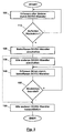
- Fig. 3 shows a possible embodiment of the method according to the invention with reference to a flow chart.
- step 100 first the flowing currents are detected by each of the DC / DC converters, which according to the invention are boost converters. These streams are then tested in step 110 for the occurrence of a backflow. If no return current is detected, the method branches back to step 100 to recapture all streams at a later time.
- step 120 When a reverse current through one of the DC / DC converters occurs, the affected DC / DC converter is first turned off in step 120.
- a boost converter as a DC / DC converter to the boost converter switch is opened. In step 130, this is also done for the other DC / DC converters.
- step 140 the current is again detected by the affected DC / DC converter, and then it is checked in step 150 whether the return current has already ended by the measures taken. If so, the process branches back to step 140 to periodically re-monitor the flow through the affected DC / DC converter because the backflow can recur.
- the unaffected DC / DC converters are shorted in step 160, i. controlled in a way so that they do not feed any further current in the common DC link.
- the method branches directly from step 120 to step 160.
- step 120 when a reverse current occurs, a state is reached directly in which only the affected string can feed into the DC link. This reliably stops the backflow situation.
- steps 130, 140 and 150 achieve an intermediate state in which all strings can continue to feed into the intermediate circuit, with all strings having the same operating voltage, since all the DC / DC converters are switched off. This is sufficient in many cases to end the backflow situation.
Description
Die Erfindung bezieht sich auf ein Verfahren und eine Vorrichtung zum Schutz mehrerer Strings eines Photovoltaikgenerators, die parallel an einem gemeinsamen Gleichspannungszwischenkreis angeschlossen sind, vor Rückströmen.The invention relates to a method and a device for protecting a plurality of strings of a photovoltaic generator, which are connected in parallel to a common DC voltage intermediate circuit, before backflow.
Unter Rückströmen sind Ströme zu verstehen, die entgegen der Richtung der von dem Photovoltaikgenerator im ordnungsgemäßen Betrieb generierten Ströme fließen.Backflows are understood to mean currents which flow counter to the direction of the currents generated by the photovoltaic generator during proper operation.
Bei mehreren, parallel an einen gemeinsamen Gleichspannungszwischenkreis angeschlossenen Strings eines Photovoltaikgenerators kann ein Rückstrom beispielsweise dann auftreten, wenn ein einzelner String verschattet ist und so die von den anderen, unverschatteten Strings gespeiste Zwischenkreisspannung des Gleichspannungszwischenkreises einen Rückstrom durch den verschatteten String hervorruft.In the case of several strings of a photovoltaic generator connected in parallel to a common DC intermediate circuit, a return current can occur, for example, if a single string is shaded and the reverse link current of the DC intermediate circuit fed by the other unshaded strings causes a return current through the shaded string.
Die Photovoltaikmodule, aus denen die Strings eines Photovoltaikgenerators aufgebaut sind, nehmen zwar durch kleinere Rückströme keinen Schaden. Bei der Parallelschaltung einer Vielzahl von Strings besteht jedoch die Gefahr, dass ein einzelner String, der verschattet ist oder aus anderen Gründen eine deutlich geringere Ausgangsspannung aufweist als die parallel geschalteten Strings, mit Strömen von allen anderen Strings als Rückstrom beaufschlagt wird. Hierdurch wird der String schnell überlastet.The photovoltaic modules, from which the strings of a photovoltaic generator are constructed, take no damage due to smaller return currents. In the parallel connection of a plurality of strings, however, there is a risk that a single string which is shaded or, for other reasons, has a significantly lower output voltage than the strings connected in parallel, is supplied with currents from all other strings as a return current. This overloads the string quickly.
Wenn ein String mit falscher Polarität an einen gemeinsamen Sammelanschluss mehrerer Strings angeschlossen wird, schließt er die anderen an den Sammelanschluss angeschlossenen Strings kurz. Der resultierende Kurzschlussstrom, d. h. die Summe der von den anderen Strings generierten Ströme, fließt zwar nicht in Rückwärtsrichtung durch den mit falscher Polarität angeschlossenen String, aber doch entgegen der Vorwärtsrichtung eines dort korrekt angeschlossenen Strings. In jedem Fall droht durch den hohen Kurzschlussstrom von allen anderen Strings eine Beschädigung des mit falscher Polarität angeschlossenen Strings. Durch die Überlastung des betroffenen Strings können auch weitere Schäden verursacht werden, insbesondere kann es zum Ausbruch eines Feuers aufgrund einer eintretenden Überhitzung von Komponenten des betroffenen Strings kommen.If a string with the wrong polarity is connected to a common hunt group of multiple strings, it shorts the other strings connected to the hunt group. The resulting short-circuit current, ie the sum of the of the Although other strings generated currents, although not flowing in the reverse direction through the connected with the wrong polarity string, but contrary to the forward direction of a properly connected string there. In any case, the high short-circuit current of all other strings threatens damage to the string connected with the wrong polarity. Overloading of the affected string can also cause further damage, in particular it can lead to the outbreak of a fire due to an incoming overheating of components of the affected string.
Die vorliegende Erfindung beschäftigt sich mit dem Schutz von Strings bzw. von Energieerzeugungsanlagen und Konstruktionen wie Gebäuden, mit denen die Energieerzeugungsanlagen verbunden oder an denen diese installiert sind, vor derartigen Überlasturigen. Es ist hierbei wünschenswert, einen Schutzgrad zu erreichen, der diese Vorrichtungen bei Auftreten eines einzelnen, beliebigen Fehlers sicher schützt.The present invention is concerned with the protection of strings or power generating plants and structures, such as buildings, with which the power generation plants are connected or installed, against such overloads. It is desirable to achieve a level of protection that will safely protect these devices when a single fault occurs.
Die vorliegende Erfindung ist insbesondere zur Anwendung bei einer Photovoltaikanlage vorgesehen, bei der der Gleichspannungszwischenkreis ein Eingangszwischenkreis eines Wechselrichters ist, der elektrische Energie von dem Photovoltaikgenerator beispielsweise in ein öffentliches Wechselstromnetz einspeist.The present invention is particularly intended for use in a photovoltaic system in which the DC link is an input link of an inverter that feeds electrical energy from the photovoltaic generator, for example, into a public AC grid.
Aus der
Aus der
Aus der
Aus der
Aus der
Weiterhin offenbart die
Der Erfindung liegt die Aufgabe zugrunde, ein Verfahren und eine Vorrichtung zum Schutz mehrerer Strings eines Photovoltaikgenerators, die parallel an einen gemeinsamen Gleichspannungszwischenkreis angeschlossen sind, vor Rückströmen bereitzustellen, deren Realisation mit einem nur minimalen Hardwareaufwand verbunden ist.The invention has for its object to provide a method and apparatus for protecting multiple strings of a photovoltaic generator, which are connected in parallel to a common DC voltage intermediate circuit, before return currents, the realization of which is associated with a minimal hardware cost.
Die Aufgabe der Erfindung wird durch ein Verfahren mit den Merkmalen des unabhängigen Patentanspruchs 1 und durch eine Vorrichtung mit den Merkmalen des unabhängigen Patentanspruchs 8 gelöst. Bevorzugte Ausführungsformen des erfindungsgemäßen Verfahrens und der erfindungsgemäßen Vorrichtung sind in den abhängigen Patentansprüchen beschrieben.The object of the invention is achieved by a method having the features of independent claim 1 and by an apparatus having the features of
Die Erfindung betrifft ein Verfahren zum Schutz mehrerer Strings eines Photovoltaikgenerators, die in Kleingruppen über jeweils einen Hochsetzsteller als DC/DC-Wandler parallel an einen gemeinsamen Gleichspannungszwischenkreis angeschlossen sind, vor Rückströmen, wobei der über jeden der DC/DC-Wandler fließende Strom erfasst wird und wobei ein auftretender Rückstrom durch einen der DC/DC-Wandler durch dauerhaftes Öffnen oder Schließen von Hochsetzstellerschaltern (21) der anderen DC/DC-Wandler beendet wird. Es versteht sich, dass nicht zwingend jeder auch nur kleine auftretende Rückstrom durch einen der DC/DC-Wandler beendet werden muss, sondern dass vielmehr ein Grenzwert für einen zu beendenden Rückstrom durch jeden der DC/DC-Wandler gesetzt werden kann. Dadurch können unnötige Auslösungen des Ansteuerns der DC/DC-Wandler zur Beendigung des Rückstroms vermieden werden.The invention relates to a method for protecting a plurality of strings of a photovoltaic generator, which are connected in small groups via a step-up converter as a DC / DC converter in parallel to a common DC voltage intermediate circuit before back currents, wherein the current flowing through each of the DC / DC converter current is detected and wherein any occurring reverse current through one of the DC / DC converters is terminated by permanently opening or closing boost converter switches (21) of the other DC / DC converters. It goes without saying that it is not compulsory for any even small reverse current to be terminated by one of the DC / DC converters, but rather that a limit value for a return current to be terminated can be set by each of the DC / DC converters. As a result, unnecessary tripping the driving of the DC / DC converter to terminate the return current can be avoided.
Weiterhin betrifft die Erfindung eine Vorrichtung zum Schutz mehrerer Strings eines Photovoltaikgenerators, die in Kleingruppen über jeweils einen Hochsetzsteller als DC/DC-Wandler parallel an einen gemeinsamen Gleichspannungszwischenkreis angeschlossen sind, vor Rückströmen, wobei jedem DC/DC-Wandler ein Stromsensor zugeordnet ist, der den über diesen DC/DC-Wandler, fließenden Strom erfasst, und wobei eine zentrale Steuerung einen auftretenden Rückstrom durch einen der DC/DC-Wandler durch dauerhaftes Öffnen oder Schließen von Hochsetzstellerschaltern (21) der anderen DC/DC-Wandler beendet. Die erfindungsgemäße Vorrichtung kann Teil einer Energieerzeugungsanlage sein.Furthermore, the invention relates to a device for protecting a plurality of strings of a photovoltaic generator, which are connected in small groups via a boost converter as a DC / DC converter in parallel to a common DC voltage intermediate circuit before back currents, each DC / DC converter is associated with a current sensor, the detects the current flowing through this DC / DC converter, and wherein a central controller terminates an occurring reverse current through one of the DC / DC converters by permanently opening or closing boost converter switches (21) of the other DC / DC converters. The device according to the invention can be part of a power generation plant.
Durch das erfindungsgemäße Verfahren bzw. die erfindungsgemäße Vorrichtung kann ein einfehlersicheres Verhalten einer übergeordneten Energieerzeugungsanlage erreicht, Werden. Dies bedeutet, dass ein beliebiger, einzelner Fehler nicht dazu führen kann, dass die Energieerzeugungsanlage in einem unsicheren, beispielsweise potenziell brandauslösenden, Zustand gelangt bzw. dort verbleibt. Dieses Verhalten kann ohne zusätzliche Bauteile durch eine angepasste Steuerung erreicht werden.By the method according to the invention or the device according to the invention, a failsafe behavior of a superordinate power generation plant can be achieved. This means that any single failure can not cause the power plant to enter or remain in an unsafe, potentially fire-prone, state. This behavior can be achieved without additional components through a customized control.
Unter einem String wird hier eine Reihenschaltung mehrerer, in der Regel einer Vielzahl von Photovoltaikmodulen verstanden. Ein String kann dabei grundsätzlich mehrere einander parallel geschaltete Teilstrings aufweisen. Vorzugsweise ist dies jedoch nicht der Fall.A string is understood to mean here a series connection of several, usually a plurality of photovoltaic modules. A string can basically have several partial strings connected in parallel. However, this is preferably not the case.
Unter einem Rückstrom durch einen DC/DC-Wandler wird hier ein Strom verstanden, mit dem elektrische Energie von dem Gleichspannungszwischenkreis in die Strings fließt, die über den DC/DC-Wandler an den Gleichspannungszwischenkreis angeschlossen sind. D. h. ein Rückstrom durch einen DC/DC-Wandler weist eine umgekehrte Richtung zu dem Strom auf, der von den Strings in den Gleichspannungszwischenkreis fließen soll. Ein solcher Rückstrom durch einen der DC/DC-Wandler weist auf einen Fehler hin, der mit einem kritischen Strom, insbesondere einem Rückstrom, durch einen der daran angeschlossenen Strings verbunden ist. Dies gilt bereits dann, wenn der Rückstrom durch den der DC/DC-Wandler nur klein ist und damit als Rückstrom durch einen der angeschlossenen Strings unkritisch wäre. Bei der vorliegenden Erfindung werden nur die Ströme durch die DC/DC-Wandler auf auftretende Rückströme überwacht. Dennoch wird ein Schutz vor Überlastungen von allen angeschlossenen Strings erreicht.A return current through a DC / DC converter is understood here to mean a current with which electrical energy flows from the DC voltage intermediate circuit into the strings, which are connected to the DC voltage intermediate circuit via the DC / DC converter. Ie. a return current through a DC / DC converter has a reverse direction to the current which is intended to flow from the strings into the DC intermediate circuit. Such a return current through one of the DC / DC converters indicates an error which is associated with a critical current, in particular a return current, through one of the strings connected thereto. This already applies if the return current through which the DC / DC converter is only small and thus would not be critical as a return current through one of the connected strings. In the present invention, only the currents through the DC / DC converters are monitored for occurring return currents. Nevertheless, protection against overloads of all connected strings is achieved.
Unter einer Kleingruppe ist hier eine so geringe Anzahl von Strings zu verstehen, dass weder bei einer aufgrund von Verschattung oder aus anderen Gründen geringeren Ausgangsspannung eines der Strings noch bei Anschluss eines der Strings mit falscher Polarität der Strom von den anderen Strings der Kleingruppe durch den einen String zu einer Beschädigung des einen Strings führt. Sicher ist dies der Fall, wenn die Kleingruppe aus zwei Strings oder gar nur einem String besteht. Bevorzugt besteht sie aus zwei Strings, um zwar einerseits die Sicherheit zu maximieren, aber andererseits die Anzahl der DC/DC-Wandler gegenüber nur einem String je DC/DC-Wandler zu halbieren.A small group is to be understood here as having a small number of strings, that neither in the case of a lower output voltage due to shading or other reasons, nor if one of the strings with the wrong polarity is connected, does the current flow from the other strings of the small group through one string String causes damage to one string. This is certainly the case if the small group consists of two strings or even only one string. Preferably, it consists of two strings, on the one hand to maximize security, but on the other hand to halve the number of DC / DC converters compared to only one string per DC / DC converter.
Erfindungsgemäß wird ein auftretender Rückstrom durch einen der DC/DC-Wandler, der zu einer Überlastung eines darüber angeschlossenen Strings führen kann, durch geeignetes Ansteuern der DC/DC-Wandler beendet. Dies ist grundsätzlich dadurch möglich, dass der DC/DC-Wandler, an dem der Rückstrom auftritt, daraufhin angesteuert wird, den Rückstrom zu unterbrechen.According to the invention, an occurring reverse current through one of the DC / DC converters, which can lead to an overload of a string connected thereto, terminated by suitably driving the DC / DC converter. This is basically possible because the DC / DC converter, where the return current occurs, is then triggered to interrupt the return current.
Es ist daher grundsätzlich bevorzugt, einen auftretenden Rückstrom durch einen der DC/DC-Wandler durch Ansteuern der anderen DC/DC-Wandler zur Unterbrechung des Stromflusses von den über sie angeschlossenen Strings in den gemeinsamen Gleichspannungszwischenkreis zu beenden.It is therefore generally preferred to terminate an occurring reverse current through one of the DC / DC converters by driving the other DC / DC converters to interrupt the current flow from the strings connected via them into the common DC voltage intermediate circuit.
Da es sich bei dem DC/DC-Wandler um Hochsetzsteller handelt, die für ein unabhängiges MPP-Tracking der über sie angeschlossenen Strings nutzbar sind, kann ein auftretender Rückstrom durch einen der DC/DC-Wandler durch Schließen von Hochsetzstellerschaltern der anderen DC/DC-Wandler beendet werden. Durch dieses Schließen der Hochsetzstellerschalter werden die anderen DC/DC-Wandler kurzgeschlossen. Die Hochsetzstellerdioden der anderen DC/DC-Wandler verhindern dabei, dass über die Hochsetzstellerschalter auch der Gleichspannungszwischenkreis kurzgeschlossen wird.Since the DC / DC converter is a step-up converter that can be used for independent MPP tracking of the strings connected across it, an occurring reverse current through one of the DC / DC converters can be achieved by closing boost converter switches of the other DC / DC Converters are stopped. By closing the boost converter switch, the other DC / DC converters are short-circuited. The boost converter diodes of the other DC / DC converters prevent the DC link from being short-circuited via the boost converter switches.
Vor dem Schließen der Hochsetzstellerschalter der anderen DC/DC-Wandler kann versucht werden, den Rückstrom durch den einen DC/DC-Wandler bereits durch Öffnen der Hochsetzstellerschalter der anderen DC/DC-Wandler zu beenden. Dadurch wird deren hochsetzstellende Funktion abgeschaltet und die an dem gemeinsamen Gleichspannungszwischenkreis anliegende Spannung, die den Rückstrom treibt, reduziert.Before closing the boost converter switches of the other DC / DC converters, it is possible to attempt to terminate the return current through one DC / DC converter already by opening the boost converter switches of the other DC / DC converters. As a result, their hochsetzstellende function is turned off and the voltage applied to the common DC voltage intermediate voltage, which drives the return current, reduced.
Solange die Hochsetzstellerdioden funktionstüchtig sind, schützen sie bei dieser Ausführungsform der Erfindung zudem die einzelnen DC/DC-Wandler vor dem Auftreten von Rückströmen. Das heißt, ein Rückstrom aus dem Gleichspannungszwischenkreis durch einen der DC/DC-Wandler kann nur dann auftreten, wenn seine Hochsetzstellerdiode defekt ist und nicht mehr sperrt. Allein die Hochsetzstellerdioden verhindern damit, dass Strings, die mit falscher Polarität angeschlossen werden, mit Strömen beaufschlagt werden, die von den Strings anderer Untergruppen generiert wurden.As long as the boost converter diodes are functional, they also protect the individual DC / DC converters from the occurrence of reverse currents in this embodiment of the invention. That is, a return current from the DC voltage intermediate circuit through one of the DC / DC converter can only occur when its boost converter diode is defective and no longer locks. Only the boost converter diodes prevent strings being connected with the wrong polarity from being supplied with currents generated by the strings of other subgroups.
Wenn nur einer von zwei Strings einer Untergruppe mit falscher Polarität angeschlossen ist, registriert der Stromsensor des zugehörigen DC/DC-Wandlers keinen oder einen ungewöhnlich geringen Strom durch den DC/DC-Wandler. Wenn beide Strings der jeweiligen Untergruppe mit falscher Polarität angeschlossen sind oder die Untergruppe nur einen mit falscher Polarität angeschlossenen String umfasst, registriert der Stromsensor einen begrenzten Rückstrom. Da dieser Fall bereits das Auftreten von zwei Fehlern umfasst, ist er für die. Betrachtung einer Einfehlersicherheit nicht relevant, wird hier aber zur weiteren Erläuterung der Erfindung betrachtet. Hingegen wirkt sich eine defekte Hochsetzstellerdiode in Verbindung mit einem Rückstrom von den anderen, über die anderen DC/DC-Wandler angeschlossenen Strings in einen erhöhten Rückstrom aus, der bei geöffnetem Hochsetzstellerschalter fließt, während er bei geschlossenem Hochsetzstellerschalter kurzgeschlossen ist. Auf diese Weise können diese Fälle durch Analyse des Auftretens des Rückstroms, insbesondere durch dessen Höhe und/oder dessen Abhängigkeit vom Schaltzustand des zugeordneten Hochsetzstellerschalters, unterschieden werden. Entsprechend ist es denkbar, ein dem Ergebnis der Analyse zugeordnetes Fehlersignal zu erzeugen. Das Fehlersignal kann zumindest einen ersten Zustand aufweisen, der einer defekten Hochsetzstellerdiode zugeordnet ist und einen zweiten Zustand, der einem oder mehreren mit falscher Polarität angeschlossenen Strings entspricht.If only one of two strings of a sub-group with the wrong polarity is connected, the current sensor of the associated DC / DC converter registers no or an unusually low current through the DC / DC converter. If both strings of the respective subgroup are connected with the wrong polarity or the subgroup has only one string connected with the wrong polarity, the current sensor registers a limited reverse current. Since this case already includes the occurrence of two errors, it is for the. Considering a single-fault security is not relevant, but will be considered here for further explanation of the invention. On the other hand, a defective boost converter diode in conjunction with a return current from the other strings connected across the other DC / DC converters will result in increased reverse current flowing with the boost converter switch open while shorted with the boost boost switch closed. In this way, these cases can be analyzed by analyzing the occurrence of the backflow, in particular by its height and / or its dependence on the switching state of the associated boost converter switch, can be distinguished. Accordingly, it is conceivable to generate an error signal associated with the result of the analysis. The error signal may include at least a first state associated with a defective boost converter diode and a second state corresponding to one or more strings connected with incorrect polarity.
Bei der voranstehenden Beschreibung ist davon ausgegangen, dass die Stromsensoren der als Hochsetzsteller ausgebildeten DC/DC-Wandler auf der den Strings zugewandten Eingangsseite der DC/DC-Wandler, d. h. vor dem jeweiligen Hochsetzstellerschalter, angeordnet sind.In the above description, it has been assumed that the current sensors of the DC / DC converters designed as boost converters are located on the input side of the DC / DC converters facing the strings, ie. H. are arranged in front of the respective boost converter switch.
Wenn ein Rückstrom erfindungsgemäß durch Schließen der Hochsetzstellerschalter der anderen DC/DC-Wandler in Form von Hochsetzstellern beendet wurde, wird vorzugsweise der Hochsetzstellerschalter des einen DC/DC-Wandlers, über den der Rückstrom aufgetreten ist, dauerhaft geöffnet. Dann speisen die über diesen DC/DC-Wandler an den Gleichspannungszwischenkreis angeschlossenen Strings den Gleichspannungszwischenkreis zumindest mit so viel elektrischer Energie, dass ein Notbetrieb eines hieran angeschlossenen Wechselrichters bzw. seiner Steuerung, die sich ebenfalls aus dem Gleichspannungszwischenkreis speist, möglich ist.If, according to the invention, a reverse current has been terminated by closing the boost converter switches of the other DC / DC converters in the form of boost converters, the boost converter switch of the one DC / DC converter through which the reverse current has occurred is permanently opened. The strings connected to the DC intermediate circuit via this DC / DC converter then supply the DC intermediate circuit with at least so much electrical energy that an emergency operation of an inverter connected thereto or its control, which also feeds from the DC intermediate circuit, is possible.
Wenn bei einer erfindungsgemäßen Vorrichtung ein oder mehrere Strings mit falscher Polarität über einen als Hochsetzsteller ausgebildeten Wechselrichter an den Gleichspannungszwischenkreis angeschlossen sind, der zugleich eine defekte Hochsetzstellerdiode aufweist, führt das Schließen der Hochsetzstellerschalter der anderen DC/DC-Wandler ebenfalls zur Unterbrechung des Rückstroms, soweit dieser von den an die anderen DC/DC-Wandler angeschlossenen Strings ausgeht. In diesem Fall, der wegen des Auftretens mehrerer unabhängiger Fehler für die Betrachtung einer Einfehlersicherheit ebenfalls nicht relevant ist, erfolgt jedoch nach Öffnen des Hochstellstellerschalters des DC/DC-Wandlers, an dem der Rückstrom aufgetreten ist, keine Aufladung des Gleichspannungszwischenkreises mit Hilfe der hieran angeschlossenen Strings, zumindest nicht mit der gewünschten Polarität. In dieser speziellen Konfiguration ist ein Schließen auch des Hochsetzstellerschalters des Hochsetzstellers mit der defekten Hochsetzstellerdiode vorteilhaft.If, in a device according to the invention, one or more strings with the wrong polarity are connected to the DC intermediate circuit via an inverter designed as a step-up converter, which also has a defective step-up diode, the closing of the step-up switch of the other DC / DC converters likewise leads to the interruption of the return current this emanates from the connected to the other DC / DC converter strings. In this case, which is also not relevant because of the occurrence of several independent errors for the consideration of a single-fault safety, but after opening the high-position switch of the DC / DC converter on which the reverse current has occurred, no charging of the DC voltage intermediate circuit using the connected thereto Strings, at least not with the desired polarity. In this particular configuration, closing the boost converter switch of the boost converter with the defective boost converter diode is also advantageous.
Die Stromsensoren der erfindungsgemäßen Vorrichtung, die den einzelnen DC/DC-Wandlern zugeordnet sind, werden zur Durchführung eines getrennten MPP-Trackings mit den einzelnen DC/DC-Wandlern sowieso benötigt. Die Hochsetzsteller sind gleichzeitig die üblichen DC/DC-Wandler, mit denen ein solches getrenntes MPP-Tracking für einzelne Strings bei sogenannten Multistringwechselrichtern durchgeführt wird. Ausschließlich von den Hochsetzstellerschaltern und Hochsetzstellerdioden solcher Hochsetzsteller macht die Erfindung Gebrauch. Zusätzliche Schalter oder Dioden werden nicht benötigt. Anders gesagt kann die Erfindung bei einem Multistringwechselrichter, der mehrere parallel geschaltete Hochsetzsteller für das separate MPP-Tracking aufweist, im Wesentlichen durch Softwaremodifikationen realisiert werden, wenn die Stromsensoren der einzelnen DC/DC-Wandler auch zur Erfassung von Rückströmen geeignet sind.The current sensors of the device according to the invention associated with the individual DC / DC converters are used to perform a separate MPP tracking with the individual DC / DC converters needed anyway. The boost converters are at the same time the usual DC / DC converters, with which such a separate MPP tracking for individual strings in so-called multi-string inverters is performed. The invention makes use of the boost converter switches and boost converter diodes of such boost converters only. Additional switches or diodes are not needed. In other words, in a multi-string inverter having a plurality of parallel-connected boost converters for separate MPP tracking, the invention can be realized substantially by software modifications, if the current sensors of the individual DC / DC converters are also suitable for detecting reverse currents.
Vorteilhafte Weiterbildungen der Erfindung ergeben sich aus den Patentansprüchen, der Beschreibung und den Zeichnungen. Die in der Beschreibung genannten Vorteile von Merkmalen und von Kombinationen mehrerer Merkmale sind lediglich beispielhaft und können alternativ oder kumulativ zur Wirkung kommen, ohne dass die Vorteile zwingend von erfindungsgemäßen Ausführungsformen erzielt werden müssen. Ohne dass hierdurch der Gegenstand der beigefügten Patentansprüche verändert wird, gilt hinsichtlich des Offenbarungsgehalts der ursprünglichen Anmeldungsunterlagen und des Patents Folgendes: weitere Merkmale sind den Zeichnungen - insbesondere der relativen Anordnung und Wirkverbindung mehrerer Bauteile zueinander - zu entnehmen. Die Kombination von Merkmalen unterschiedlicher Ausführungsformen der Erfindung oder von Merkmalen unterschiedlicher Patentansprüche ist ebenfalls abweichend von den gewählten Rückbeziehungen der Patentansprüche möglich und wird hiermit angeregt. Dies betrifft auch solche Merkmale, die in separaten Zeichnungen dargestellt sind oder bei deren Beschreibung genannt werden. Diese Merkmale können auch mit Merkmalen unterschiedlicher Patentansprüche kombiniert werden. Ebenso können in den Patentansprüchen aufgeführte Merkmale für weitere Ausführungsformen der Erfindung entfallen.Advantageous developments of the invention will become apparent from the claims, the description and the drawings. The advantages of features and of combinations of several features mentioned in the description are merely exemplary and can take effect alternatively or cumulatively, without the advantages having to be achieved by embodiments according to the invention. Without altering the subject matter of the appended claims, the following applies to the disclosure content of the original application documents and the patent: Further features can be found in the drawings - in particular the relative arrangement and operative connection of several components to one another. The combination of features of different embodiments of the invention or of features of different claims is also possible deviating from the chosen relationships of the claims and is hereby stimulated. This also applies to those features which are shown in separate drawings or are mentioned in their description. These features can also be combined with features of different claims. Likewise, in the claims listed features for further embodiments of the invention can be omitted.
Die in den Patentansprüchen und der Beschreibung genannten Merkmale sind bezüglich ihrer Anzahl so zu verstehen, dass genau diese Anzahl oder eine größere Anzahl als die genannte Anzahl vorhanden ist, ohne dass es einer expliziten Verwendung des Adverbs "mindestens" bedarf. Wenn also beispielsweise von einem Element die Rede ist, ist dies so zu verstehen, dass genau ein Element, zwei Elemente oder mehr Elemente vorhanden sind. Diese Merkmale können durch andere Merkmale ergänzt werden oder die einzigen Merkmale sein, aus denen das jeweilige Erzeugnis besteht.The features mentioned in the patent claims and the description are to be understood in terms of their number that exactly this number or a greater number than the said number is present, without requiring an explicit use of the adverb "at least". For example, when talking about an element, it should be understood that there is exactly one element, two elements or more elements. These features may be supplemented by other features or be the only characteristics that make up the product in question.
Die in den Patentansprüchen enthaltenen Bezugszeichen stellen keine Beschränkung des Umfangs der durch die Patentansprüche geschützten Gegenstände dar. Sie dienen lediglich dem Zweck, die Patentansprüche leichter verständlich zu machen.The reference numerals contained in the claims do not limit the scope of the objects protected by the claims. They are for the sole purpose of making the claims easier to understand.
Im Folgenden wird die Erfindung anhand in den Figuren dargestellter bevorzugter Ausführungsbeispiele weiter erläutert und beschrieben.
- Fig. 1
- ist ein Prinzipschaltbild einer erfindungsgemäßen Vorrichtung, die zwischen einzelne Strings eines Photovoltaikgenerators und einen Eingangszwischenkreis eines Wechselrichters geschaltet ist.
- Fig. 2
- ist ein Prinzipschaltbild einer konkreteren Ausführungsform der erfindungsgemäßen Vorrichtung, ebenfalls geschaltet zwischen Strings eines Photovoltaikgenerators und den Eingangszwischenkreis eines Wechselrichters, wobei zwei verschiedene potentielle Fehler illustriert sind.
- Fig. 3
- zeigt ein Flussdiagramm einer Ausführungsform des erfindungsgemäßen Verfahrens.
- Fig. 1
- is a schematic diagram of a device according to the invention, which is connected between individual strings of a photovoltaic generator and an input intermediate circuit of an inverter.
- Fig. 2
- is a schematic diagram of a more concrete embodiment of the device according to the invention, also connected between strings of a photovoltaic generator and the input intermediate circuit of an inverter, wherein two different potential errors are illustrated.
- Fig. 3
- shows a flowchart of an embodiment of the method according to the invention.
Um die in dem Gleichspannungszwischenkreis 4 verfügbare elektrische Energie zu maximieren, sind die DC/DC-Wandler 8 für ein individuelles MPP-Tracking der an sie angeschlossenen Strings 2 ausgebildet. Das heißt, die DC/DC-Wandler 8 passen den Betriebspunkt, d. h. die Betriebsspannung, der an sie angeschlossenen Strings 2 gegenüber der Zwischenkreisspannung des Gleichspannungszwischenkreises 4 so an, dass die von diesen Strings 2 generierte elektrische Leistung maximiert wird. Neben der Ausgangsspannung der Strings 2 ist dabei der durch den jeweiligen DC/DC-Wandler 8 fließende Strom zu messen, um die aktuelle Leistung bestimmen zu können. Die Messung des Stroms erfolgt mit einem Stromsensor 15.In order to maximize the electrical energy available in the
Der Stromsensor 15 wird auch dazu genutzt, das Auftreten von Rückströmen zu erkennen, die der normalen Stromflussrichtung von den Strings 2 in den Gleichspannungszwischenkreis 4 entgegengerichtet sind. Derartige Rückströme können die Integrität der Strings 2 gefährden, insbesondere wenn es sich hierbei um die Ströme von vielen anderen Strings 2 handelt, die durch diese einzelnen Strings fließen. Wenn ein solcher Rückstrom durch einen der DC/DC-Wandler 8 auftritt, steuert eine Steuerung 16, die die mit den Stromsensoren 15 gemessenen Ströme, insbesondere Rückströme 17, als Eingangssignale 23 erhält, die DC/DC-Wandler 8 so an, dass der Rückstrom beendet wird. Was hierzu genau zu unternehmen ist, hängt von der Art der DC/DC-Wandler 8 ab.The
Wenn die DC/DC-Wandler 8 in einem nicht zur Erfindung gehörenden Ausführungsbeispiel. Tiefsetzsteller sind, können die Tiefsetzstellerschalter der anderen DC/DC-Wandler, an denen kein Rückstrom aufgetreten ist, geöffnet werden, um die über sie angeschlossenen Strings 2 von dem Gleichspannungszwischenkreis 4 zu trennen. Der Gleichspannungszwischenkreis 4 wird dann nur noch von den Strings 2 aufgeladen, zu denen zuvor der Rückstrom floss. In jedem Fall steuert die Steuerung 16 zur Beendigung des Rückstroms nur die sowieso zum individuellen MPP-Tracking vorgesehenen DC/DC-Wandler 8 an und keine zusätzlichen Trennschalter oder dergleichen an. Es sind auch keine zusätzlichen Dioden vorgesehen, die einen Rückstrom verhindern. Dabei wird hingenommen, dass von dem jeweils einen der paarweise an einen DC/DC-Wandler 8 angeschlossenen Strings 2 ein Rückstrom in den jeweils anderen fließen kann, weil dieser Rückstrom auf den von diesem einen String 2 generierten Strom begrenzt ist. Auch der Anschluss eines Strings 2 mit falscher Polarität, so dass er einen parallel geschalteten String kurzschließt, führt maximal dazu, dass der Kurzschlussstrom eines Strings 2 durch die beiden an einen DC/DC-Wandler 8 angeschlossenen Strings 2 fließt. Einen solchen Stromwert erlauben die Strings 2 dauerhaft, ohne hierdurch beschädigt zu werden oder zu überhitzen. Falls in einer nicht gezeigten Ausführungsform drei Strings 2 an einem DC/DC-Wandler 8 angeschlossen werden, führt die Verpolung eines einzelnen Strings 2' entsprechend maximal zur Bestromung dieses Strings mit dem doppelten Kurzschlussstrom, erzeugt durch die beiden anderen Strings. Auch diese Belastung vertragen viele Strings dauerhaft und schadlos. Häufig ist daher die Konfiguration mit drei Strings wegen der geringeren Zahl von DC/DC-Wandlern bei gegebener Stringzahl vorteilhaft. Bei belastungssensitiven Modulen ist hingegen die Konfiguration mit nur zwei Strings 2 je DC/DC-Wandler 8 vorzuziehen.When the DC /
In
In
Durch die Ausbildung der DC/DC-Wandler 8 als Hochsetzsteller 18 wirken jedoch deren Hochsetzstellerdioden 19 grundsätzlich als Sperren für Rückströme aus dem Gleichspannungszwischenkreis 4 zu den an den jeweiligen DC/DC-Wandler 8 angeschlossenen Strings 2. Solche Rückströme können daher grundsätzlich nur dann auftreten, wenn eine Hochsetzstellerdiode 19 defekt ist. Dies ist bei dem oberen DC/DC-Wandler 8 in
Ein Rückstrom durch einen der Stromsensoren 15 kann grundsätzlich auch auftreten, wenn beide an den entsprechenden DC/DC-Wandler 8 angeschlossenen Strings 2 mit falscher Polarität angeschlossen sind, was erneut kein bei ausschließlicher Betrachtung der Einfehlersicherheit zu berücksichtigender Fall ist. Dieser Rückstrom fließt über den in der Regel nur vorwärts sperrenden zugehörigen Hochsetzstellerschalter 21. Er kann zwar von der Steuerung nicht durch Öffnen der Hochsetzstellerschalter 21 der anderen DC/DC-Wandler 8 beendet werden, kann aber gerade hierdurch erkannt werden. Als solcher ist ein Rückstrom durch einen DC/DC-Wandler 8 von zwei mit falscher Polarität daran angeschlossen Strings 2 unkritisch, da er nicht über den Strom hinaus geht, der beim Kurzschließen der an einen der anderen DC/DC-Wandler angeschlossenen Strings mit dessen Hochsetzstellerschalter fließt.In principle, a return current through one of the
In
Sofern der Rückstrom nicht bereits durch das Abschalten aller DC/DC-Wandler beendet werden kann, werden die nicht betroffenen DC/DC-Wandler in Schritt 160 kurzgeschlossen, d.h. in einer Weise angesteuert, so dass sie keinen weiteren Strom in den gemeinsamen Zwischenkreis einspeisen.Unless the return current can be terminated by switching off all DC / DC converters, the unaffected DC / DC converters are shorted in
In einer möglichen Alternative verzweigt das Verfahren direkt von Schritt 120 zu Schritt 160. Hierdurch wird bei Auftreten eines Rückstromes unmittelbar ein Zustand erreicht, in dem nur noch der betroffene String in den Zwischenkreis einspeisen kann. Dies beendet zuverlässig die Rückstromsituation. Durch die Schritte 130, 140 und 150 wird demgegenüber ein Zwischenzustand erreicht, in dem alle Strings weiterhin in den Zwischenkreis einspeisen können, wobei alle Strings die gleiche Betriebsspannung aufweisen, da alle DC/DC-Wandler abgeschaltet sind. Dies ist in vielen Fällen ausreichend, um die Rückstromsituation zu beenden.In one possible alternative, the method branches directly from
Abschließend ist noch einmal hervorzuheben, dass in der Vorrichtung 1 im Stromfluss von den Strings 2 zu dem Gleichspannungszwischenkreis 4 keine elektrischen oder elektronischen Bauteile vorgesehen sind, die nicht sowieso für das individuelle MPP-Tracking der jeweils an einen der DC/DC-Wandler 8 angeschlossenen Strings 2 benötigt werden.Finally, it should be emphasized once again that no electrical or electronic components are provided in the device 1 in the current flow from the
- 11
- Vorrichtungcontraption
- 22
- Stringstring
- 2'2 '
- Stringstring
- 33
- Photovoltaikgeneratorphotovoltaic generator
- 44
- GleichspannungszwischenkreisDc link
- 55
- Wechselrichterinverter
- 66
- Anschlussconnection
- 77
- Anschlussconnection
- 88th
- DC/DC-WandlerDC / DC converter
- 99
- Busleitungbus line
- 1010
- Busleitungbus line
- 1111
- Anschlussconnection
- 1212
- Anschlussconnection
- 1313
- ZwischenkreiskondensatorLink capacitor
- 1414
- WechselspannungsnetzAC network
- 1515
- Stromsensorcurrent sensor
- 1616
- Steuerungcontrol
- 1717
- Rückstromreverse current
- 1818
- HochsetzstellerBoost converter
- 1919
- HochsetzstellerdiodeUp converter diode
- 2020
- KurzschlusspfadShort-circuit path
- 2121
- HochsetzstellerschalterUp converter switch
- 2222
- HochsetzstellerdrosselUp converter inductor
- 2323
- Eingangssignalinput
Claims (12)
- A method for reverse current (17) protection of a number of strings (2) of a photovoltaic generator (3) being connected to a common DC link (4) in parallel in small groups respectively via a corresponding boost converter (18), characterized in that the current flowing via each of the boost converters (18) is detected, and a reverse current (17) flowing through one of the boost converters (18) is inhibited by permanent opening or closing of boost converter switches (21) of the other boost converters (18).
- The method as claimed in claim 1, characterized in that the small groups each comprise two or three strings (2).
- The method as claimed in one of the above claims, characterized in that the reverse current (17) flowing through one of the boost converters (18) is inhibited by the control of the other boost converters (18) for interrupting the current flow from the strings (2) respectively connected to the common DC link (4).
- The method as claimed in claim 1, characterized in that the boost converter switches (21) of the other boost converters (18) are initially opened, and it is confirmed whether the reverse current (17) has been inhibited, and in that the boost converter switches (21) of the other boost converters (18) are subsequently closed, if the reverse current (17) has not been inhibited by the opening of the boost converter switches (21) of the other boost converters (18).
- The method as claimed in claim 4, characterized in that, once the reverse current (17) has been inhibited by the closing of the boost converter switches (21) of the other boost converters (18), a boost converter switch (21) of the one of the boost converter (18), in which the reverse current has occurred, is opened.
- The method as claimed in one of the above claims, characterized in that, in response to a reverse current (17), an error signal is generated.
- A device for reverse current (17) protection of a number of strings (2) of a photovoltaic generator (3) being connected to a common DC link (4) in parallel in small groups respectively via a corresponding boost converter (18), characterized in that each boost converter (18) is associated with a current sensor (15) detecting the current flowing via said boost converter (18), and in that a central control system (16) is provided configured to inhibit the flow of a reverse current (17) through one of the boost converters (18) by permanent opening or closing of boost converter switches (21) of the other boost converters (18).
- The device as claimed in claim 7, characterized in that the small groups each comprise two or three strings (2).
- The device as claimed in claim 7 or 8, characterized in that the control system (16) is configured to inhibit the reverse current (17) flowing through one of the boost converters (18) by the control of the other boost converters (18) for interrupting the current flow from the strings (2) respectively connected to the common DC link (4).
- The device as claimed in claim 7, characterized in that the control system (16) is configured to initially open the boost converter switches (21) of the other boost converters (18), and to confirm whether the reverse current (17) has been inhibited, and configured to subsequently close the boost converter switches (21) of the other boost converters (18), if the reverse current (17) has not been inhibited by the opening of the boost converter switches (21) of the other boost converters (18).
- The device as claimed in one of claims 7 or 10, characterized in that the control system (16) is configured to open a boost converter switch (21) on the one of the boost converter (18) in which the reverse current (17) has occurred, if the reverse current (17) has been inhibited by the closing of the boost converter switches (21) of the other boost converters (18).
- The device as claimed in one of claims 7 to 11, characterized in that the control system (16) is configured to generate an error signal in response to the occurrence of a reverse current (17).
Applications Claiming Priority (2)
| Application Number | Priority Date | Filing Date | Title |
|---|---|---|---|
| DE102012112184.2A DE102012112184A1 (en) | 2012-12-12 | 2012-12-12 | Method and device for protecting multiple strings of a photovoltaic generator from backflow |
| PCT/EP2013/076114 WO2014090815A2 (en) | 2012-12-12 | 2013-12-10 | Method and device for protecting several strings of a photovoltaic generator from return currents |
Publications (2)
| Publication Number | Publication Date |
|---|---|
| EP2920858A2 EP2920858A2 (en) | 2015-09-23 |
| EP2920858B1 true EP2920858B1 (en) | 2016-06-22 |
Family
ID=49759294
Family Applications (1)
| Application Number | Title | Priority Date | Filing Date |
|---|---|---|---|
| EP13802966.5A Active EP2920858B1 (en) | 2012-12-12 | 2013-12-10 | Method and device for protecting several strings of a photovoltaic generator from return currents |
Country Status (6)
| Country | Link |
|---|---|
| US (1) | US9806516B2 (en) |
| EP (1) | EP2920858B1 (en) |
| JP (1) | JP6112687B2 (en) |
| CN (1) | CN104919671B (en) |
| DE (1) | DE102012112184A1 (en) |
| WO (1) | WO2014090815A2 (en) |
Families Citing this family (14)
| Publication number | Priority date | Publication date | Assignee | Title |
|---|---|---|---|---|
| DE102012203836B4 (en) * | 2012-03-12 | 2020-03-12 | Rct Power Gmbh | Circuit arrangement and method for converting and adjusting a DC voltage, photovoltaic system |
| CN105827179B (en) * | 2015-01-04 | 2018-09-07 | 华为技术有限公司 | A kind of photovoltaic system |
| US10404060B2 (en) | 2015-02-22 | 2019-09-03 | Abb Schweiz Ag | Photovoltaic string reverse polarity detection |
| JP6488963B2 (en) * | 2015-09-28 | 2019-03-27 | 株式会社デンソー | Power supply system control device and power supply unit |
| US20170331363A1 (en) * | 2016-05-13 | 2017-11-16 | Altera Corporation | Current Limited Power Converter Circuits And Methods |
| CN106130067B (en) * | 2016-07-15 | 2018-06-15 | 东莞理工学院 | A kind of photovoltaic generating system and method |
| CN107947736B (en) * | 2017-12-28 | 2023-08-25 | 扬州华鼎电器有限公司 | Photovoltaic power generation elastic control device and control method thereof |
| JP7067155B2 (en) * | 2018-03-14 | 2022-05-16 | オムロン株式会社 | Power conditioner |
| EP3605813A1 (en) | 2018-07-30 | 2020-02-05 | Fronius International GmbH | Inverter with intermediate circuit protection |
| GB2585173A (en) | 2018-11-12 | 2021-01-06 | Eaton Intelligent Power Ltd | Photovoltaic string combiner box with protection functions |
| CN114128067A (en) * | 2019-07-11 | 2022-03-01 | 三菱电机株式会社 | DC distribution board |
| CN110888085A (en) * | 2019-11-29 | 2020-03-17 | 华为数字技术(苏州)有限公司 | Inverter short circuit detection method and device and inverter |
| WO2021207880A1 (en) | 2020-04-13 | 2021-10-21 | 华为技术有限公司 | Short circuit protection apparatus, short circuit protection method, and photovoltaic power generation system |
| CN112332669B (en) * | 2020-11-11 | 2022-05-24 | 阳光电源股份有限公司 | MLPE photovoltaic system and photovoltaic string control method thereof |
Family Cites Families (10)
| Publication number | Priority date | Publication date | Assignee | Title |
|---|---|---|---|---|
| DE10120595B4 (en) | 2000-04-28 | 2004-08-05 | Sharp K.K. | Solar Energy System |
| US20070107767A1 (en) | 2005-11-16 | 2007-05-17 | Arizona Public Service Company | DC power-generation system and integral control apparatus therefor |
| US8816535B2 (en) * | 2007-10-10 | 2014-08-26 | Solaredge Technologies, Ltd. | System and method for protection during inverter shutdown in distributed power installations |
| US8013472B2 (en) * | 2006-12-06 | 2011-09-06 | Solaredge, Ltd. | Method for distributed power harvesting using DC power sources |
| EP2104200B1 (en) * | 2008-03-22 | 2019-02-27 | SMA Solar Technology AG | Method for controlling a multi-string inverter for photovoltaic systems |
| DE102009032288A1 (en) | 2009-07-09 | 2011-01-13 | Kostal Industrie Elektrik Gmbh | photovoltaic system |
| ES2384426T3 (en) | 2009-08-06 | 2012-07-04 | Sma Solar Technology Ag | Return current sensor for solar modules connected in parallel |
| EP2282388A1 (en) | 2009-08-06 | 2011-02-09 | SMA Solar Technology AG | Device for feeding in electrical energy of a number of strings of photovoltaic modules in an electricity network |
| US20120080943A1 (en) * | 2010-09-30 | 2012-04-05 | Astec International Limited | Photovoltaic Power Systems |
| WO2012046331A1 (en) * | 2010-10-07 | 2012-04-12 | 東芝三菱電機産業システム株式会社 | Failure detecting apparatus |
-
2012
- 2012-12-12 DE DE102012112184.2A patent/DE102012112184A1/en not_active Withdrawn
-
2013
- 2013-12-10 JP JP2015546981A patent/JP6112687B2/en active Active
- 2013-12-10 EP EP13802966.5A patent/EP2920858B1/en active Active
- 2013-12-10 CN CN201380070356.6A patent/CN104919671B/en active Active
- 2013-12-10 WO PCT/EP2013/076114 patent/WO2014090815A2/en active Application Filing
-
2015
- 2015-06-12 US US14/737,712 patent/US9806516B2/en active Active
Non-Patent Citations (1)
| Title |
|---|
| None * |
Also Published As
| Publication number | Publication date |
|---|---|
| EP2920858A2 (en) | 2015-09-23 |
| US9806516B2 (en) | 2017-10-31 |
| JP6112687B2 (en) | 2017-04-12 |
| US20150280423A1 (en) | 2015-10-01 |
| WO2014090815A2 (en) | 2014-06-19 |
| WO2014090815A3 (en) | 2014-08-07 |
| CN104919671A (en) | 2015-09-16 |
| DE102012112184A1 (en) | 2014-06-12 |
| CN104919671B (en) | 2017-12-19 |
| JP2016506227A (en) | 2016-02-25 |
Similar Documents
| Publication | Publication Date | Title |
|---|---|---|
| EP2920858B1 (en) | Method and device for protecting several strings of a photovoltaic generator from return currents | |
| EP2284973B1 (en) | Reverse current sensor for solar modules connected in parallel | |
| EP3047556B1 (en) | Circuit arrangement for a photovoltaic inverter for break relief using short-circuit switches, and uses of said circuit arrangement | |
| WO2018046651A1 (en) | Multi-string photovoltaic system, method for operating same and string disconnection device for same | |
| EP2597764B1 (en) | Method for handling failures in a modular multilevel converter and such a converter | |
| EP2367253B1 (en) | Photovoltaic fields, some with switches to bypass modules | |
| EP2567406A1 (en) | Method for limiting the generator voltage of a photovoltaic installation in case of danger and photovoltaic installation | |
| EP2764595B1 (en) | Method for protecting an intermediate circuit capacitor in a power converter circuit | |
| EP2296244A1 (en) | Method and device for connecting at least one string of a photovoltaic assembly with an inverter | |
| DE102012109012B4 (en) | Circuit arrangement for a solar power plant with a DC voltage source for an offset voltage | |
| DE102016117049A1 (en) | Multi-strand photovoltaic system, method for operating such and reverse current protection circuit for such | |
| WO2011098235A2 (en) | Module bypass circuit for a photovoltaic module | |
| EP2815434B1 (en) | Switching-off of solar modules | |
| DE102011117178A1 (en) | Inverter with bridgeable reverse current protection device | |
| DE102013111869A1 (en) | Photovoltaic system i.e. outdoor system, for producing current, has alternating current-shortcircuit switch arranged before alternating current-separating element in energy flow direction, and diode associated to photovoltaic-sub generators | |
| EP2096756B1 (en) | Separating device for a voltage semiconductor and method for operating same, power module and system assembly | |
| DE102017107801A1 (en) | Photovoltaic system, DC hybrid switching device, use and method for turning on and off a photovoltaic string | |
| DE102015115284B3 (en) | Protective device for an electrical power supply device and electrical power supply device with such a protective device | |
| EP2479859B1 (en) | Safety circuit | |
| DE102017107800A1 (en) | Multi-strand photovoltaic system, method for operating such and strand shutdown device for such | |
| BE1024328B1 (en) | Multi-strand photovoltaic system, method for operating such and strand shutdown device for such | |
| LU93202B1 (en) | Multi-strand photovoltaic system, method for operating such and reverse current protection circuit for such | |
| AT524421B1 (en) | Method for time grading protection-compatible selective monitoring of the operation of an electrical energy network with the detection of short-circuits | |
| DE102012106505A1 (en) | De-energizing device in photovoltaic strand, has circuit breaker to temporarily disconnect direct voltage of photovoltaic strand to power source unit, and safety device to open circuit breaker when earthing switch is closed previously | |
| EP2608343B1 (en) | Power supply |
Legal Events
| Date | Code | Title | Description |
|---|---|---|---|
| PUAI | Public reference made under article 153(3) epc to a published international application that has entered the european phase |
Free format text: ORIGINAL CODE: 0009012 |
|
| 17P | Request for examination filed |
Effective date: 20150619 |
|
| AK | Designated contracting states |
Kind code of ref document: A2 Designated state(s): AL AT BE BG CH CY CZ DE DK EE ES FI FR GB GR HR HU IE IS IT LI LT LU LV MC MK MT NL NO PL PT RO RS SE SI SK SM TR |
|
| AX | Request for extension of the european patent |
Extension state: BA ME |
|
| RIN1 | Information on inventor provided before grant (corrected) |
Inventor name: LASCHINSKI, JOACHIM Inventor name: WALTER, MATTHIAS Inventor name: HAERING, ADRIAN Inventor name: BREMICKER, SVEN Inventor name: WOLF, HENRIK |
|
| GRAP | Despatch of communication of intention to grant a patent |
Free format text: ORIGINAL CODE: EPIDOSNIGR1 |
|
| RIC1 | Information provided on ipc code assigned before grant |
Ipc: H02J 7/35 20060101ALI20160114BHEP Ipc: H02J 1/10 20060101AFI20160114BHEP Ipc: H02H 7/20 20060101ALI20160114BHEP Ipc: H02H 11/00 20060101ALI20160114BHEP Ipc: H02M 3/155 20060101ALI20160114BHEP Ipc: H02J 3/38 20060101ALI20160114BHEP Ipc: H02J 1/00 20060101ALI20160114BHEP Ipc: H02M 1/32 20070101ALI20160114BHEP Ipc: H02H 7/10 20060101ALI20160114BHEP |
|
| DAX | Request for extension of the european patent (deleted) | ||
| INTG | Intention to grant announced |
Effective date: 20160209 |
|
| GRAP | Despatch of communication of intention to grant a patent |
Free format text: ORIGINAL CODE: EPIDOSNIGR1 |
|
| GRAS | Grant fee paid |
Free format text: ORIGINAL CODE: EPIDOSNIGR3 |
|
| GRAA | (expected) grant |
Free format text: ORIGINAL CODE: 0009210 |
|
| INTG | Intention to grant announced |
Effective date: 20160502 |
|
| AK | Designated contracting states |
Kind code of ref document: B1 Designated state(s): AL AT BE BG CH CY CZ DE DK EE ES FI FR GB GR HR HU IE IS IT LI LT LU LV MC MK MT NL NO PL PT RO RS SE SI SK SM TR |
|
| REG | Reference to a national code |
Ref country code: GB Ref legal event code: FG4D Free format text: NOT ENGLISH |
|
| REG | Reference to a national code |
Ref country code: CH Ref legal event code: EP |
|
| REG | Reference to a national code |
Ref country code: IE Ref legal event code: FG4D Free format text: LANGUAGE OF EP DOCUMENT: GERMAN |
|
| REG | Reference to a national code |
Ref country code: AT Ref legal event code: REF Ref document number: 808164 Country of ref document: AT Kind code of ref document: T Effective date: 20160715 |
|
| REG | Reference to a national code |
Ref country code: DE Ref legal event code: R096 Ref document number: 502013003497 Country of ref document: DE |
|
| REG | Reference to a national code |
Ref country code: LT Ref legal event code: MG4D |
|
| REG | Reference to a national code |
Ref country code: NL Ref legal event code: MP Effective date: 20160622 |
|
| PG25 | Lapsed in a contracting state [announced via postgrant information from national office to epo] |
Ref country code: NO Free format text: LAPSE BECAUSE OF FAILURE TO SUBMIT A TRANSLATION OF THE DESCRIPTION OR TO PAY THE FEE WITHIN THE PRESCRIBED TIME-LIMIT Effective date: 20160922 Ref country code: LT Free format text: LAPSE BECAUSE OF FAILURE TO SUBMIT A TRANSLATION OF THE DESCRIPTION OR TO PAY THE FEE WITHIN THE PRESCRIBED TIME-LIMIT Effective date: 20160622 Ref country code: FI Free format text: LAPSE BECAUSE OF FAILURE TO SUBMIT A TRANSLATION OF THE DESCRIPTION OR TO PAY THE FEE WITHIN THE PRESCRIBED TIME-LIMIT Effective date: 20160622 |
|
| PG25 | Lapsed in a contracting state [announced via postgrant information from national office to epo] |
Ref country code: RS Free format text: LAPSE BECAUSE OF FAILURE TO SUBMIT A TRANSLATION OF THE DESCRIPTION OR TO PAY THE FEE WITHIN THE PRESCRIBED TIME-LIMIT Effective date: 20160622 Ref country code: GR Free format text: LAPSE BECAUSE OF FAILURE TO SUBMIT A TRANSLATION OF THE DESCRIPTION OR TO PAY THE FEE WITHIN THE PRESCRIBED TIME-LIMIT Effective date: 20160923 Ref country code: SE Free format text: LAPSE BECAUSE OF FAILURE TO SUBMIT A TRANSLATION OF THE DESCRIPTION OR TO PAY THE FEE WITHIN THE PRESCRIBED TIME-LIMIT Effective date: 20160622 Ref country code: LV Free format text: LAPSE BECAUSE OF FAILURE TO SUBMIT A TRANSLATION OF THE DESCRIPTION OR TO PAY THE FEE WITHIN THE PRESCRIBED TIME-LIMIT Effective date: 20160622 Ref country code: HR Free format text: LAPSE BECAUSE OF FAILURE TO SUBMIT A TRANSLATION OF THE DESCRIPTION OR TO PAY THE FEE WITHIN THE PRESCRIBED TIME-LIMIT Effective date: 20160622 Ref country code: NL Free format text: LAPSE BECAUSE OF FAILURE TO SUBMIT A TRANSLATION OF THE DESCRIPTION OR TO PAY THE FEE WITHIN THE PRESCRIBED TIME-LIMIT Effective date: 20160622 |
|
| REG | Reference to a national code |
Ref country code: FR Ref legal event code: PLFP Year of fee payment: 4 |
|
| PG25 | Lapsed in a contracting state [announced via postgrant information from national office to epo] |
Ref country code: EE Free format text: LAPSE BECAUSE OF FAILURE TO SUBMIT A TRANSLATION OF THE DESCRIPTION OR TO PAY THE FEE WITHIN THE PRESCRIBED TIME-LIMIT Effective date: 20160622 Ref country code: IT Free format text: LAPSE BECAUSE OF FAILURE TO SUBMIT A TRANSLATION OF THE DESCRIPTION OR TO PAY THE FEE WITHIN THE PRESCRIBED TIME-LIMIT Effective date: 20160622 Ref country code: IS Free format text: LAPSE BECAUSE OF FAILURE TO SUBMIT A TRANSLATION OF THE DESCRIPTION OR TO PAY THE FEE WITHIN THE PRESCRIBED TIME-LIMIT Effective date: 20161022 Ref country code: SK Free format text: LAPSE BECAUSE OF FAILURE TO SUBMIT A TRANSLATION OF THE DESCRIPTION OR TO PAY THE FEE WITHIN THE PRESCRIBED TIME-LIMIT Effective date: 20160622 Ref country code: RO Free format text: LAPSE BECAUSE OF FAILURE TO SUBMIT A TRANSLATION OF THE DESCRIPTION OR TO PAY THE FEE WITHIN THE PRESCRIBED TIME-LIMIT Effective date: 20160622 Ref country code: CZ Free format text: LAPSE BECAUSE OF FAILURE TO SUBMIT A TRANSLATION OF THE DESCRIPTION OR TO PAY THE FEE WITHIN THE PRESCRIBED TIME-LIMIT Effective date: 20160622 |
|
| PG25 | Lapsed in a contracting state [announced via postgrant information from national office to epo] |
Ref country code: PL Free format text: LAPSE BECAUSE OF FAILURE TO SUBMIT A TRANSLATION OF THE DESCRIPTION OR TO PAY THE FEE WITHIN THE PRESCRIBED TIME-LIMIT Effective date: 20160622 Ref country code: SM Free format text: LAPSE BECAUSE OF FAILURE TO SUBMIT A TRANSLATION OF THE DESCRIPTION OR TO PAY THE FEE WITHIN THE PRESCRIBED TIME-LIMIT Effective date: 20160622 Ref country code: ES Free format text: LAPSE BECAUSE OF FAILURE TO SUBMIT A TRANSLATION OF THE DESCRIPTION OR TO PAY THE FEE WITHIN THE PRESCRIBED TIME-LIMIT Effective date: 20160622 Ref country code: PT Free format text: LAPSE BECAUSE OF FAILURE TO SUBMIT A TRANSLATION OF THE DESCRIPTION OR TO PAY THE FEE WITHIN THE PRESCRIBED TIME-LIMIT Effective date: 20161024 |
|
| REG | Reference to a national code |
Ref country code: DE Ref legal event code: R097 Ref document number: 502013003497 Country of ref document: DE |
|
| PLBE | No opposition filed within time limit |
Free format text: ORIGINAL CODE: 0009261 |
|
| STAA | Information on the status of an ep patent application or granted ep patent |
Free format text: STATUS: NO OPPOSITION FILED WITHIN TIME LIMIT |
|
| 26N | No opposition filed |
Effective date: 20170323 |
|
| PG25 | Lapsed in a contracting state [announced via postgrant information from national office to epo] |
Ref country code: DK Free format text: LAPSE BECAUSE OF FAILURE TO SUBMIT A TRANSLATION OF THE DESCRIPTION OR TO PAY THE FEE WITHIN THE PRESCRIBED TIME-LIMIT Effective date: 20160622 Ref country code: BE Free format text: LAPSE BECAUSE OF NON-PAYMENT OF DUE FEES Effective date: 20161231 |
|
| REG | Reference to a national code |
Ref country code: CH Ref legal event code: PL |
|
| PG25 | Lapsed in a contracting state [announced via postgrant information from national office to epo] |
Ref country code: SI Free format text: LAPSE BECAUSE OF FAILURE TO SUBMIT A TRANSLATION OF THE DESCRIPTION OR TO PAY THE FEE WITHIN THE PRESCRIBED TIME-LIMIT Effective date: 20160622 |
|
| PG25 | Lapsed in a contracting state [announced via postgrant information from national office to epo] |
Ref country code: MC Free format text: LAPSE BECAUSE OF FAILURE TO SUBMIT A TRANSLATION OF THE DESCRIPTION OR TO PAY THE FEE WITHIN THE PRESCRIBED TIME-LIMIT Effective date: 20160622 |
|
| REG | Reference to a national code |
Ref country code: IE Ref legal event code: MM4A |
|
| PG25 | Lapsed in a contracting state [announced via postgrant information from national office to epo] |
Ref country code: LI Free format text: LAPSE BECAUSE OF NON-PAYMENT OF DUE FEES Effective date: 20161231 Ref country code: CH Free format text: LAPSE BECAUSE OF NON-PAYMENT OF DUE FEES Effective date: 20161231 Ref country code: LU Free format text: LAPSE BECAUSE OF NON-PAYMENT OF DUE FEES Effective date: 20161210 |
|
| PG25 | Lapsed in a contracting state [announced via postgrant information from national office to epo] |
Ref country code: IE Free format text: LAPSE BECAUSE OF NON-PAYMENT OF DUE FEES Effective date: 20161210 |
|
| REG | Reference to a national code |
Ref country code: FR Ref legal event code: PLFP Year of fee payment: 5 |
|
| REG | Reference to a national code |
Ref country code: BE Ref legal event code: MM Effective date: 20161231 |
|
| PG25 | Lapsed in a contracting state [announced via postgrant information from national office to epo] |
Ref country code: HU Free format text: LAPSE BECAUSE OF FAILURE TO SUBMIT A TRANSLATION OF THE DESCRIPTION OR TO PAY THE FEE WITHIN THE PRESCRIBED TIME-LIMIT; INVALID AB INITIO Effective date: 20131210 |
|
| PG25 | Lapsed in a contracting state [announced via postgrant information from national office to epo] |
Ref country code: MK Free format text: LAPSE BECAUSE OF FAILURE TO SUBMIT A TRANSLATION OF THE DESCRIPTION OR TO PAY THE FEE WITHIN THE PRESCRIBED TIME-LIMIT Effective date: 20160622 Ref country code: CY Free format text: LAPSE BECAUSE OF FAILURE TO SUBMIT A TRANSLATION OF THE DESCRIPTION OR TO PAY THE FEE WITHIN THE PRESCRIBED TIME-LIMIT Effective date: 20160622 |
|
| PG25 | Lapsed in a contracting state [announced via postgrant information from national office to epo] |
Ref country code: BG Free format text: LAPSE BECAUSE OF FAILURE TO SUBMIT A TRANSLATION OF THE DESCRIPTION OR TO PAY THE FEE WITHIN THE PRESCRIBED TIME-LIMIT Effective date: 20160622 |
|
| PG25 | Lapsed in a contracting state [announced via postgrant information from national office to epo] |
Ref country code: MT Free format text: LAPSE BECAUSE OF FAILURE TO SUBMIT A TRANSLATION OF THE DESCRIPTION OR TO PAY THE FEE WITHIN THE PRESCRIBED TIME-LIMIT Effective date: 20160622 |
|
| PG25 | Lapsed in a contracting state [announced via postgrant information from national office to epo] |
Ref country code: AL Free format text: LAPSE BECAUSE OF FAILURE TO SUBMIT A TRANSLATION OF THE DESCRIPTION OR TO PAY THE FEE WITHIN THE PRESCRIBED TIME-LIMIT Effective date: 20160622 Ref country code: TR Free format text: LAPSE BECAUSE OF FAILURE TO SUBMIT A TRANSLATION OF THE DESCRIPTION OR TO PAY THE FEE WITHIN THE PRESCRIBED TIME-LIMIT Effective date: 20160622 |
|
| REG | Reference to a national code |
Ref country code: AT Ref legal event code: MM01 Ref document number: 808164 Country of ref document: AT Kind code of ref document: T Effective date: 20181210 |
|
| PG25 | Lapsed in a contracting state [announced via postgrant information from national office to epo] |
Ref country code: AT Free format text: LAPSE BECAUSE OF NON-PAYMENT OF DUE FEES Effective date: 20181210 |
|
| PGFP | Annual fee paid to national office [announced via postgrant information from national office to epo] |
Ref country code: GB Payment date: 20231220 Year of fee payment: 11 |
|
| PGFP | Annual fee paid to national office [announced via postgrant information from national office to epo] |
Ref country code: FR Payment date: 20231219 Year of fee payment: 11 Ref country code: DE Payment date: 20231214 Year of fee payment: 11 |