EP1143090B1 - Système de clef électronique pour véhicule - Google Patents
Système de clef électronique pour véhicule Download PDFInfo
- Publication number
- EP1143090B1 EP1143090B1 EP01302932A EP01302932A EP1143090B1 EP 1143090 B1 EP1143090 B1 EP 1143090B1 EP 01302932 A EP01302932 A EP 01302932A EP 01302932 A EP01302932 A EP 01302932A EP 1143090 B1 EP1143090 B1 EP 1143090B1
- Authority
- EP
- European Patent Office
- Prior art keywords
- door
- vehicle
- electronic key
- lock
- condition
- Prior art date
- Legal status (The legal status is an assumption and is not a legal conclusion. Google has not performed a legal analysis and makes no representation as to the accuracy of the status listed.)
- Expired - Lifetime
Links
Images


Classifications
-
- B—PERFORMING OPERATIONS; TRANSPORTING
- B60—VEHICLES IN GENERAL
- B60R—VEHICLES, VEHICLE FITTINGS, OR VEHICLE PARTS, NOT OTHERWISE PROVIDED FOR
- B60R25/00—Fittings or systems for preventing or indicating unauthorised use or theft of vehicles
- B60R25/20—Means to switch the anti-theft system on or off
- B60R25/24—Means to switch the anti-theft system on or off using electronic identifiers containing a code not memorised by the user
- B60R25/245—Means to switch the anti-theft system on or off using electronic identifiers containing a code not memorised by the user where the antenna reception area plays a role
-
- B—PERFORMING OPERATIONS; TRANSPORTING
- B60—VEHICLES IN GENERAL
- B60R—VEHICLES, VEHICLE FITTINGS, OR VEHICLE PARTS, NOT OTHERWISE PROVIDED FOR
- B60R25/00—Fittings or systems for preventing or indicating unauthorised use or theft of vehicles
-
- G—PHYSICS
- G07—CHECKING-DEVICES
- G07C—TIME OR ATTENDANCE REGISTERS; REGISTERING OR INDICATING THE WORKING OF MACHINES; GENERATING RANDOM NUMBERS; VOTING OR LOTTERY APPARATUS; ARRANGEMENTS, SYSTEMS OR APPARATUS FOR CHECKING NOT PROVIDED FOR ELSEWHERE
- G07C9/00—Individual registration on entry or exit
- G07C9/00174—Electronically operated locks; Circuits therefor; Nonmechanical keys therefor, e.g. passive or active electrical keys or other data carriers without mechanical keys
- G07C9/00309—Electronically operated locks; Circuits therefor; Nonmechanical keys therefor, e.g. passive or active electrical keys or other data carriers without mechanical keys operated with bidirectional data transmission between data carrier and locks
-
- G—PHYSICS
- G07—CHECKING-DEVICES
- G07C—TIME OR ATTENDANCE REGISTERS; REGISTERING OR INDICATING THE WORKING OF MACHINES; GENERATING RANDOM NUMBERS; VOTING OR LOTTERY APPARATUS; ARRANGEMENTS, SYSTEMS OR APPARATUS FOR CHECKING NOT PROVIDED FOR ELSEWHERE
- G07C2209/00—Indexing scheme relating to groups G07C9/00 - G07C9/38
- G07C2209/60—Indexing scheme relating to groups G07C9/00174 - G07C9/00944
- G07C2209/63—Comprising locating means for detecting the position of the data carrier, i.e. within the vehicle or within a certain distance from the vehicle
Definitions
- the present invention relates to a vehicular electronic key system for unlocking/locking vehicular doors and starting an engine.
- the electronic key system includes an electronic key and an on-vehicle apparatus which is communicable with the electronic key by means of wireless communication, and identifies ID (identification data) between the electronic key and the on-vehicle apparatus to permit the door unlocking/locking operation and the engine starting operation.
- a Japanese Utility Model Provisional Registered No. 2511202 discloses a vehicular electronic key system arranged to warn a driver that an electronic key has been mislaid in a passenger compartment when the driver opened a driver door.
- Such a vehicular electronic key system requires a large magnetic field generator or a plurality of small magnetic field generators, which can form a magnetic field in a vehicle passenger compartment, so that the system can detect an electronic key mislaid in a passenger compartment.
- This provision of such a large magnet field generator or plurality of small magnetic field generators increases energy consumption of a vehicle.
- EP-A-0 523 602 discloses a system and a method in accordance with the preambles of claims 1 and 9 respectively.
- the present invention provides an electronic key system as set forth in claim 1, and a method for warning mislaying an electronic key in a passenger compartment in a vehicle, as set forth in claim 9.
- FIG. 1 to 7B there is shown a first embodiment of a vehicular electronic key system according to the present invention.
- Vehicular electronic key system comprises an on-vehicle apparatus 1 shown in Fig. 1, an electronic key 20 shown in Fig. 2 and an ignition switch operated by an ignition knob 30 shown in Fig. 3.
- on-vehicle apparatus 1 of the vehicular electronic key system comprises passive control unit 11, first, second and third transmitters 2, 3 and 4, a receiver 12, an unlock and lock controller 13, an engine controller 15, a steering lock unit 16 and a buzzer 17.
- Unlock and lock controller 13 is connected to a door lock actuator 14 through which vehicular doors are opened and closed. Further, on-vehicle apparatus 1 is connected to various switches as explained later.
- electronic key 20 comprises a transceiver 21, an electronic key controller 22 and a battery 23.
- Electronic key controller 22 comprises a CPU 22a and a nonvolatile memory 22b of a peripheral equipment.
- Electronic key 20 executes radio communication with on-vehicle apparatus 1 through an antenna 21a of transceiver 21.
- Nonvolatile memory 22b stores ID (Identification Data) for identifying a person having electronic key 20 as a permitted driver.
- Battery 23 is exchangeable and supplies electric power to electronic key controller 22.
- Electronic key 20 has no key plate employed in a conventional ignition key and is formed into a card which is further portable for a driver as compared with a conventional key.
- No cylinder unit for receiving electronic key 20 is provided in on-vehicle apparatus 1. It is not necessary for the driver to set electronic key 20 at a predetermined position, and the driver may merely carry electronic key 20.
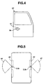
- Ignition knob 30 is installed on an instrument panel in a passenger compartment of the vehicle as shown in Fig. 3, and no key hole is provided thereto since it is not necessary to insert electronic key 20 to the ignition switch unit.
- the ignition switch unit (not-shown) operated by ignition knob 30 is connected to passive control unit 11 and comprises a key switch 5, ignition-on switch 6, an engine start switch 7, and a steering lock unit 16 for locking a steering wheel.
- Ignition knob 30 is manually operated by the driver carrying electronic key 30.
- Steering lock unit 16 comprises a turn inhibiting latch (not shown) for inhibiting the turning of ignition knob 30 by locking ignition knob 30. Accordingly, by putting this turn inhibiting latch in a turnable state, ignition knob 30 and the steering wheel are put in the turnable state.
- ignition knob 30 By pushing ignition knob 30 set at a steering lock position denoted by LOCK in Fig. 3, key switch 5 is switched on. Further, by turning ignition knob 30 to an ignition-on position denoted by ON in Fig. 3, ignition-on switch 6 is switched on. By further turning ignition knob 30 to an engine start position denoted by START in Fig. 3, engine start switch 7 is switched on.
- Door handle switches 8a and 8b for detecting the operation of door handles of driver and assistant doors 40 and 43 are installed to driver and assistant doors 40 and 43, respectively, and are connected to passive controller 11 in order to start a door unlock process as to doors 40 and 43 for front vehicle occupants. That is, each of door handle switches 8a and 8b is switched on when the door handle of each of doors 40 and 43 is operated to open each of doors 40 and 43.
- Door lock switches 9a and 9b for detecting whether doors 40 and 43 are locked or not are installed to doors 40 and 43 and connected to passive controller 11 in order to start a door lock process as to the doors for front seats. As shown in Fig.
- door lock switch 9a is installed at a portion near a door outside handle 41 for a driver door 40 and is operated from the outside of the vehicle when driver door 40 is locked.
- door lock switch 9b is installed at a portion near a door outside handle 41 for an assistant (front passenger) door 43.
- Door lock condition switches 10a and 10b are switches for detecting whether driver door 40 and assistant door 43 are locked or unlocked, respectively.
- Each of door lock condition switches 10a and 10b is switched off when a door lock mechanism (not shown) for each of front doors 40 and 43 is put in a lock condition, and is switched on when the door lock mechanism is put in an unlock condition.
- On-vehicle apparatus 1 communicates with electronic key 20 through first, second and third transmitters 2, 3 and 4 and a receiver 12 by means of wireless communication.
- First transmitter 2 is installed at the driver seat or a ceiling above the drive seat.
- First transmitter 2 sends an engine start signal to electronic key 20 through an antenna 2a.
- antenna 2a By controlling the directivity of antenna 2a, a communicable area between on-vehicle apparatus 1 and electronic key 20 is limited within an area of a passenger compartment near the driver seat.
- the communicable area may be limited in an area where first transmitter 2 can send the signal to electronic key 20 carried by a driver seated on the driver seat.
- second transmitter 3 is installed in the vicinity of door outside handle 41 of driver door 40 and sends a door lock signal and a door unlock signal through a driver-door antenna 3a to electronic key 20 carried by the driver who is found near driver door 40.
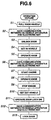
- the communicable area between on-vehicle apparatus 1 and electronic key 20 is limited within an area 42 of an outside near driver door 40 as shown in Fig. 5.
- the communicable area 42 may be limited in an area where second transmitter 3 can send the signal to electronic key 20 carried by a driver who will execute a door lock by operating door lock switch 9a.
- third transmitter 4 is installed in the vicinity of door outside handle 41 of assistant door 43 and sends a door lock signal and a door unlock signal through an assistant-door antenna 4a to electronic key 20 carried by the driver who is found near assistant door 43.
- a communicable area between on-vehicle apparatus 1 and electronic key 20 is limited within an area 44 of an outside near assistant door 43.
- the communicable area 44 may be limited in a range where third transmitter 4 can send the signal to electronic key 20 carried by a vehicle occupant who will execute a door lock by operating door lock switch 9b.
- Receiver 12 is installed at a rear parcel located at a vehicle rear portion, and receives an engine start request signal, a lock request signal, an unlock request signal and the key ID from electronic key 20 through an antenna 12a.
- Unlock and lock controller 13 comprises a CPU 13a and a nonvolatile memory 13b and executes locking and unlocking operations of driver door 40, assistant door 43, rear-passenger doors by controlling door lock actuator 14.
- Engine controller 15 comprises a CPU 15a and a nonvolatile memory 15b and controls an engine speed and an output torque of an engine by controlling a throttle valve control apparatus, a fuel injection apparatus and an ignition apparatus executes locking and unlocking operations of driver door 40, assistant door 43, the rear-passenger doors by controlling door lock actuator 14.
- Passive control unit 11 comprises a CPU 11a and a nonvolatile memory 11b, and executes the door unlocking and locking operations and the engine starting and stopping operations through radio communication with electronic key 20 via transmitters 2, 3 and 4 and receiver 12. More specifically, passive control unit 11 executes the door unlocking and locking operations and the engine starting and stopping operations in a manner of controlling unlock and lock controller 13 and engine controller 15 according to the set conditions of ignition switches 5 to 7, door handle switches 8a and 8b, door lock switches 9a and 9b, and lock condition switches 10a and 10b.
- a buzzer 17 is connected to passive control unit 11 in order to warn that electronic key 20 is mislaid in the vehicle, and is installed at a position from which a vehicle occupant outside of the vehicle can hear the alarm of buzzer 17. It is certain that a speaker may be provided instead of buzzer 7 and may inform the alarm condition to the vehicle occupant by voice.
- FIG. 6 A flowchart of Fig. 6 schematically shows a procedure of the door unlock process, the engine start process and the door lock process in the first embodiment. First, the procedure of these processes will be schematically discussed in time series with reference to Fig. 6.
- on-vehicle apparatus 1 checks at step S1 whether one of door handle switches 8a and 8b is switched on. When one of door handle switches 8a and 8b is switched on, the routine proceeds to step S2.
- on-vehicle apparatus 1 communicates with electronic key 20 to send and receive information as to the door unlock operation. More specifically, on-vehicle apparatus 1 sends a door unlock signal to electronic key 20 through one of second transmitter 3 having antenna 3a and third transmitter 4 having antenna 4a. In reply to this signal, electronic key 20 sends an unlock request signal and the key ID to on-vehicle apparatus 1.
- on-vehicle apparatus 1 decides whether the key ID sent from electronic key 20 corresponds with the apparatus ID stored in memory 13b, and unlocks doors 40 and 43 when the key ID sent from electronic key 20 corresponds with the apparatus ID. More specifically, unlock and lock controller 13 of on-vehicle apparatus 1 receives the unlock request signal and the key ID from electronic key 20 through receiver 12, and identifies the received key ID with the registered ID stored in memory 13b. When the key ID corresponds with the apparatus ID stored in memory 13b, on-vehicle apparatus 1 unlocks doors 40 and 43 in a manner that unlock and lock controller 13 controls door lock actuator 14.
- on-vehicle apparatus 1 communicates with electronic key 20 to send and receive information as to the engine start operation. More specifically, an engine start signal is sent from on-vehicle apparatus 1 to electronic key 20 through first transmitter 2 having antenna 2a. In reply to this signal, electronic key 20 sends an engine start request signal and the key ID for starting the engine to on-vehicle apparatus 1. On-vehicle apparatus 1 identifies the key ID for starting the engine with the registered ID for starting the engine.
- step S7 the engine is started in reply to the correspondence result between the received key ID for starting the engine and the registered ID for starting the engine.
- step S9 on-vehicle apparatus 1 stops the engine by controlling engine controller 15.
- door lock switches 9a and 9b are switched on.
- on-vehicle apparatus 1 communicates with electronic key 20 to send and receive information as to the door lock operation. More specifically, a door lock signal is sent from on-vehicle apparatus 1 to electronic key 20 through one of second and third transmitters 3 and 4. In reply to this signal, electronic key 20 sends an unlock request signal and the key ID to on-vehicle apparatus 1 through transceiver 21.
- on-vehicle apparatus 1 decides whether the key ID for locking doors 40 and 43 corresponds with the apparatus ID stored in memory 13b. More specifically, unlock and lock controller 13 of on-vehicle apparatus 1 receives the lock request signal and the key ID from electronic key 20 through receiver 12 and transceiver 21, and identifies the key ID with the registered ID stored in memory 13b. When the sent key ID corresponds with the apparatus ID stored in memory 13b, on-vehicle apparatus 1 locks doors 40 and 43 in a manner that unlock and lock controller 13 controls door lock actuator 14.
- on-vehicle apparatus 1 decides whether each of door lock switch 9a of driver door 40 and door lock switch 9b of assistant door 43 is switched on by the driver or other vehicle occupant from the outside of the vehicle. Since each of door lock switches 9a and 9b is installed on an outside surface of door 40, 43, on-vehicle apparatus 1 decides that a vehicle occupant outside of the vehicle is executing the door locking operation when one of door lock switches 9a and 9b is switched on. When the door lock operation is executed, that is, when one of door lock switches 9a and 9b is switched on, the routine proceeds to step S22. When neither door lock switch 9a nor 9b is not switched on, the routine jumps to an end step to terminate the present routing without locking the doors 40 and 43.
- on-vehicle apparatus 1 sends the door lock signal to electronic key 20 through second transmitter 3 and antenna 3a provided in driver door 40 in reply to the operation of door lock switch 9a of driver door 40. Further, in reply to the operation of door lock switch 9b of assistant door 43, on-vehicle apparatus 1 sends the door lock signal to electronic key 20 through third transmitter 4 and antenna 4a provided in assistant door 43.
- electronic key 20 starts awaiting the door lock signal outputted from on-vehicle apparatus 1, in reply to the start of this door lock process.
- step S23 electronic key 20 decides whether the door lock signal is received.
- the routine proceeds to step S24 wherein electronic key 20 outputs the door lock request signal and the key ID to on-vehicle apparatus 1.
- driver-door communicable area 42 is an area where on-vehicle apparatus 1 are communicable with electronic key 20 through driver-door antenna 3a and electronic key antenna 21a and is set outside of the vehicle and near driver door 40.
- assistant-door communicable area 44 is an area where on-vehicle apparatus 1 are communicable with electronic key 20 through assistant door antenna 4a and electronic key antenna 21a and is set outside of the vehicle and near assistant door 40. Therefore, only when a vehicle occupant having electronic key 20 is found outside of the vehicle and near driver door 40 or outside of the vehicle and near assistant door 43, wireless communication is established between on-vehicle apparatus 1 and electronic key 20. Accordingly, it can be decided that the vehicle occupant carries electronic key 20 and has not mislaid electronic key 20 in the vehicle when on-vehicle apparatus 1 is communicable with electronic key 20 by means of wireless communication.
- on-vehicle apparatus 1 checks for a predetermined time period whether receiver 12 receives the door lock request signal and the key ID from electronic key 20 through antenna 12a. When the door lock request signal and the key ID signal are received, the routine proceeds to step S26. When receiver 12 does not receive the door lock request and the key ID within the predetermined time period, the routine proceeds to step S28.
- on-vehicle apparatus 1 checks whether the key ID sent from electronic key 20 corresponds with the registered key ID. When the key ID sent from electronic key 20 corresponds with the registered ID stored in memory 11b, the routine proceeds to step S27. When the key ID does not correspond with the registered apparatus ID, the routine proceeds to step S28.
- on-vehicle apparatus 1 executes the locking of both doors 40 and 43 by controlling door lock actuator 14 through unlock and lock controller 13.
- on-vehicle apparatus 1 At step S28 following to the negative decision at step S25 or S26, that is, when it is decided that on-vehicle apparatus 1 does not receive the door lock request and the key ID from electronic key 20 or that the key ID does not correspond with the apparatus ID, on-vehicle apparatus 1 generates alarm by means of buzzer 17 to inform the vehicle occupant that electronic key 20 has been mislaid in a passenger compartment of the vehicle. Further, on-vehicle apparatus 1 inhibits the locking of doors 40 and 43 and terminates the present routine of the door lock process.
- FIGs. 8 to 10 there is shown a second embodiment of the electronic key system according to the present invention.
- a hardware construction of the second embodiment is the same as that of the first embodiment shown in Figs. 1 to 5, and therefore the explanation thereof is omitted herein. Only the manner of operation of the second embodiment according to the present invention will be discussed hereinafter with reference to Figs. 8 to 10.
- the operations executed in the second embodiment further takes account of a so-called keyless lock, in addition to the operations of the first embodiment shown in Fig. 6.
- the keyless lock of doors is executed with no key in a manner that a driver puts a lock mechanism of doors 40 and 43 in a lock condition by operating a door knob of opened door 40 or an integrated door lock switch and closes driver door 40 while pulling the door outside handle.
- steps S1 to S13 are completely the same as those of the first embodiment shown in Fig. 6, and therefore the explanations of steps S1 to S13 are omitted herein. Only steps S14 to S16 relating to the keyless lock will be discussed hereinafter.
- a driver may execute the door lock process without using electronic key 20. More specifically, the driver may lock driver door 40 and other doors by means of the keyless lock by directly operating the door lock switch and door outside handle. In such a case, the operations in the flowchart of Fig. 8 proceeds to step S14.
- the driver executes the keyless lock of doors in a manner that the driver puts a lock mechanism of driver door 40 in the lock condition by operating a door knob of opened door 40 or an integrated door lock switch and closes driver door 40 while pulling the door outside handle.
- on-vehicle apparatus 1 executes to communicate with electronic key 20 and checks whether electronic key 20 is mislaid in the vehicle compartment or not.
- on-vehicle apparatus 1 cannot communicate with electronic key 20 or when the key ID does not correspond with the apparatus ID though on-vehicle apparatus 1 can communicate with electronic key 20, on-vehicle apparatus 1 decides that the driver has mislaid electronic key 20 in the vehicle.
- on-vehicle apparatus 1 unlocks doors and warn the driver that electronic key 20 has been mislaid in the vehicle.
- On-vehicle apparatus 1 decides whether the keyless lock was executed by operating driver door 40 or assistant door 43 through the execution of steps S31 and S32 of Fig. 9A. More specifically, at step S31 on-vehicle apparatus 1 checks whether driver-door handle switch 8a is put in ON state and whether door lock condition switch 10a is put in OFF state. That is, on-vehicle apparatus 1 checks whether the door lock mechanism of driver door 40 is put in the lock condition as a result of the keyless lock of operating the door lock knob or integrated door lock switch under the door open condition. Further, on-vehicle apparatus 1 checks whether the door lock mechanism of assistant door 43 is put in the lock condition as a result of the keyless lock of operating the door lock knob or integrated door lock switch under the door open condition. When on-vehicle apparatus 1 decides that driver door 40 or assistant door 43 was locked while being opened, the routine proceeds to step S32. When the decision at step S31 is negative, the routine repeats step S31 for a predetermined time period.
- on-vehicle apparatus 1 decides whether one of door handle switches 8a and 8b has been just switched off from ON condition. That is, on-vehicle apparatus 1 checks whether driver door 40 or assistant door 43 has just been closed. When the decision at step S32 is affirmative, that is, when driver door 40 or assistant door 43 is locked by means of the keyless lock, the routine proceeds to step S33. When the decision at step S32 is negative, the routine returns to step S31.
- on-vehicle apparatus 1 sends the door lock signal to electronic key 20 through first transmitter 3 and driver-door antenna 3a of driver door 40 when driver door 40 is locked by means of the keyless lock, and sends the door lock signal to electronic key 20 through second transmitter 4 and assistant-door antenna 4a when assistant door 43 is locked by means of the keyless lock.
- step S34 electronic key 20 decides whether the door lock signal is received.
- the routine proceeds to step S35 wherein electronic key 20 outputs the key ID to on-vehicle apparatus 1.
- driver-door communicable area 42 is an area where on-vehicle apparatus 1 are communicable with electronic key 20 through driver-door antenna 3a and electronic key antenna 21a and is set outside of the vehicle and near driver door 40.
- assistant-door communicable area 44 is an area where on-vehicle apparatus 1 are communicable with electronic key 20 through assistant-door antenna 4a and electronic key antenna 21a and is set outside of the vehicle and near assistant door 43. Therefore, only when a vehicle occupant having electronic key 20 is found outside of the vehicle and near driver door 40 or outside of the vehicle and near assistant door 43, wireless communication is established between on-vehicle apparatus 1 and electronic key 20. Accordingly, it can be decided that the vehicle occupant carries electronic key 20 and has not mislaid electronic key 20 in the vehicle when on-vehicle apparatus 1 is communicable with electronic key 20 by means of wireless communication.
- on-vehicle apparatus 1 checks for a predetermined time period whether receiver 12 receives the key ID from electronic key 20 through antenna 12a. When the key ID signal is received, the routine proceeds to step S37. When receiver 12 does not receive the key ID within the predetermined time period, the routine proceeds to step S38 of Fig. 10.
- unlock and lock controller 13 of on-vehicle apparatus 1 checks whether the key ID sent from electronic key 20 corresponds with the registered apparatus ID.
- the routine proceeds to step S27.
- the routine proceeds to step S38. That is, when on-vehicle apparatus 1 cannot communicate with electronic key 20 (corresponding to the negative decision at step S36), or when the key ID does not correspond with the registered apparatus ID (corresponding to the negative decision at step S37), on-vehicle apparatus 1 decides that the vehicle passenger does not have electronic key 20.
- on-vehicle apparatus 1 sets a counter value N at 3.
- on-vehicle apparatus 1 unlocks both doors 40 and 43 through door lock actuator 14 by the controlling unlock and lock controller 13.
- on-vehicle apparatus 1 decides whether both of door lock condition switch 10a of driver door 40 and door lock condition switch 10b of assistant door 43 are put in ON state or not. That is, on-vehicle apparatus 1 decides whether both of door lock mechanisms for driver door 40 and assistant door 43 are put in the unlock condition, the routine proceeds to step S41.
- step S43 on-vehicle apparatus 1 decides whether counter value N is equal to 0 or not.
- N ⁇ 0 the routine returns to step S39 to repeat the unlock operation. That is, in order to certainly unlock doors 40 and 43, the door unlock operation is repeated at most three times by executing these steps S38, S39, S40, S42 and S43.
- on-vehicle apparatus 1 warns the vehicle occupant that electronic key 20 was mislaid in the vehicle by operating buzzer 17.
- on-vehicle apparatus 1 decides whether one of door handle switches 8a and 8b is put in ON condition or not. That is, on-vehicle apparatus 1 decides whether one of driver door 40 and assistant door 43 is opened. When one of driver door 40 and assistant door 43 is opened, the routine proceeds to step S52. When the decision at step S51 is negative, the step S51 is repeated.
- on-vehicle apparatus 1 decides whether one of door lock condition switch 10a of driver door 40 and door lock condition switch 10b of assistant door 43 is switched off from the ON state or not. That is, on-vehicle apparatus 1 decides whether one of door lock mechanisms for driver door 40 and assistant door 43 is switched from the unlock condition to the lock condition.
- the decision at step S51 is affirmative, the routine proceeds to step S52.
- the decision at step S51 is negative, the routine returns to step S51.
- on-vehicle apparatus 1 decides whether one of door handle switch 8a of driver door 40 and door handle switch 8b of assistant door 43 has been just switched off from ON state. That is, on-vehicle apparatus 1 checks whether driver door 40 or assistant door 43 has just been closed. When the decision at step S53 is affirmative, that is, when driver door 40 or assistant door 43 is locked by means of the keyless lock, the routine proceeds to step S33 shown in Fig. 9A. When the decision at step S52 is negative, the routine returns to step S51.
- driver-door communicable area 42 is set outside of the vehicle and near driver door 40
- assistant-door communicable area 44 is set outside of the vehicle and near assistant door 40.
- on-vehicle apparatus 1 decides that the locking operation of driver door 40 or assistant door 43 was executed, and communicates with electronic key 20 by means of wireless communication.
- on-vehicle apparatus 1 decides that electronic key 20 is mislaid in the passenger compartment and generates alarm to warn the mislay of electronic key 20.
- on-vehicle apparatus 1 when on-vehicle apparatus 1 is communicable with electronic key but when the key ID of electronic key 20 does not correspond with the apparatus ID registered in on-vehicle apparatus 1, there is a possibility that the driver used another key instead of electronic key 20 to lock doors 40 and 43 while mislaying electronic key 20 in the passenger compartment. Therefore, in this situation, on-vehicle apparatus 1 generates alarm.
- the thus arranged electronic key system is capable of firmly preventing electronic key 20 from being mislaid in the passenger compartment by providing a wireless communication device having a small communicable area at the driver door or both of driver door and assistant door.
- This arrangement enables decreasing a cost of the electronic key system and decreasing electric power consumption of a battery.
Claims (9)
- Système de clé électronique pour un véhicule, comprenant:caractérisé en ce que:un appareil portable (20) qui comprend un premier dispositif de communication sans fil (21) et une première mémoire (22b) qui stocke une ID de clé [données d'identification]; etun appareil sur véhicule (1) qui est installé dans le véhicule, l'appareil sur véhicule comprenant:un second dispositif de communication sans fil (3, 4) qui peut communiquer avec le premier dispositif de communication sans fil (21) lorsque le premier dispositif de communication sans fil (21) est dans une zone prédéterminée à l'extérieur du véhicule;une seconde mémoire (13b) qui stocke une ID d'appareil;un détecteur de condition de portière qui détecte qu'une opération de verrouillage d'une portière de véhicule (40, 43) est exécutée depuis l'extérieur du véhicule; etune unité de commande (11, 13) qui permet un verrouillage de la portière de véhicule (40, 43) lorsque l'ID de clé correspond à l'ID d'appareil,l'unité de commande (11, 13) reçoit l'ID de clé en provenance de l'appareil portable (20) lorsque l'appareil sur véhicule (1) peut communiquer avec l'appareil portable (20) par l'intermédiaire des premier et second dispositifs de communication sans fil (21 et 3, 4);l'unité de commande (11, 13) émet en sortie une alarme lorsque l'opération de verrouillage de la portière de véhicule (40, 43) est exécutée depuis l'extérieur du véhicule et lorsque le second dispositif de communication sans fil (3, 4) ne peut pas communiquer avec le premier dispositif de communication sans fil (21); etl'unité de commande (11, 13) émet en sortie une alarme lorsque l'ID de clé ne correspond pas à l'ID d'appareil.
- Système de clé électronique selon la revendication 1, dans lequel le détecteur de condition de portière comprend un commutateur de verrouillage de portière (9a, 9b) qui est installé au niveau d'une partie externe de la portière de véhicule (40, 43).
- Système de clé électronique selon la revendication 1, dans lequel le détecteur de condition de portière comprend un détecteur de condition d'ouverture de portière (8a, 8b) pour détecter si oui ou non la portière de véhicule est ouverte et un détecteur de condition de verrouillage de portière (9a, 9b) pour détecter si oui ou non la portière de véhicule (40, 43) est verrouillée, le détecteur de condition de portière détectant une première condition consistant en ce que la portière de véhicule (40, 43) est ouverte et verrouillée, le détecteur de condition de portière détectant une seconde condition consistant en ce que la portière de véhicule (40, 43) est fermée après que le détecteur de condition de portière a détecté la première condition, le détecteur de condition de portière décidant que l'opération de verrouillage de la portière de véhicule est exécutée depuis l'extérieur du véhicule lorsque le détecteur de condition de portière détecte la seconde condition.
- Système de clé électronique selon la revendication 1, dans lequel le détecteur de condition de portière comprend un détecteur de condition d'ouverture de portière (8a, 8b) pour détecter si oui ou non la portière de véhicule (40, 43) est ouverte et un détecteur de condition de verrouillage de portière (9a, 9b) pour détecter si oui ou non la portière de véhicule (40, 43) est verrouillée, le détecteur de condition de portière détectant une troisième condition consistant en ce qu'une condition de verrouillage de la portière de véhicule (40, 43) est commutée depuis un état de déverrouillage selon un état de verrouillage lorsque la portière de véhicule est ouverte, le détecteur de condition de portière détectant une quatrième condition consistant en ce que la portière de véhicule est fermée après que le détecteur de condition de portière a détecté la troisième condition, le détecteur de condition de portière décidant que l'opération de verrouillage de la portière de véhicule est exécutée depuis l'extérieur du véhicule lorsque le détecteur de condition de portière détecte la quatrième condition.
- Système de clé électronique selon la revendication 1, dans lequel l'unité de commande (11, 13) peut communiquer avec l'appareil portable (20) via les premier et second dispositifs de communication sans fil (21 et 3, 4) lorsque l'appareil portable (20) est dans la zone prédéterminée.
- Système de clé électronique selon la revendication 1, dans lequel l'unité de commande (11, 13) reçoit l'ID de clé qui est stockée dans la première mémoire (22b) via les premier et second dispositifs de communication sans fil (21 et 3, 4) et vérifie si oui ou non l'ID de clé correspond à l'ID d'appareil qui est stockée dans la seconde mémoire (13b).
- Système de clé électronique selon la revendication 1, dans lequel l'unité de commande (11, 13) comprend un contrôleur de déverrouillage et de verrouillage (13) pour déverrouiller et verrouiller la portière de véhicule (40, 43) en commandant un actionneur de verrouillage de portière (14) qui est connecté au contrôleur de déverrouillage et de verrouillage, l'unité de commande verrouillant et déverrouillant la portière de véhicule en envoyant un signal de verrouillage/déverrouillage sur le contrôleur de déverrouillage et de verrouillage.
- Système de clé électronique selon la revendication 1, dans lequel l'unité de commande (11, 13) exécute une opération de déverrouillage de la portière de véhicule (40, 43) plusieurs fois jusqu'à ce que le détecteur de condition de portière détecte que la portière de véhicule est verrouillée.
- Procédé pour avertir d'un état égaré d'une clé électronique dans un compartiment de passagers dans un véhicule, le procédé comprenant:caractérisé par:l'action consistant à faire communiquer un appareil sur véhicule avec une clé électronique lorsque la clé électronique est dans une zone prédéterminée à l'extérieur du véhicule; etla détection de si oui ou non une opération de verrouillage d'une portière de véhicule est exécutée depuis l'extérieur du véhicule,la réception d'une ID de clé en provenance de la clé électronique lorsque l'appareil sur véhicule peut communiquer avec la clé électronique au moyen d'une communication sans fil;l'émission en sortie d'une alarme lorsque la portière du véhicule est verrouillée depuis l'extérieur du véhicule et que l'appareil sur véhicule ne communique pas avec la clé électronique; etl'émission en sortie d'une alarme lorsque l'ID de clé ne correspond pas à une ID d'appareil de l'appareil sur véhicule.
Applications Claiming Priority (8)
| Application Number | Priority Date | Filing Date | Title |
|---|---|---|---|
| JP2000100971 | 2000-04-03 | ||
| JP2000100971 | 2000-04-03 | ||
| JP2000100970 | 2000-04-03 | ||
| JP2000100970 | 2000-04-03 | ||
| JP2001066265 | 2001-03-09 | ||
| JP2001066265A JP3588677B2 (ja) | 2000-04-03 | 2001-03-09 | 車両用電子キー装置 |
| JP2001066264A JP3589188B2 (ja) | 2000-04-03 | 2001-03-09 | 車両用電子キー装置 |
| JP2001066264 | 2001-03-09 |
Publications (3)
| Publication Number | Publication Date |
|---|---|
| EP1143090A2 EP1143090A2 (fr) | 2001-10-10 |
| EP1143090A3 EP1143090A3 (fr) | 2001-10-17 |
| EP1143090B1 true EP1143090B1 (fr) | 2005-03-16 |
Family
ID=27481186
Family Applications (1)
| Application Number | Title | Priority Date | Filing Date |
|---|---|---|---|
| EP01302932A Expired - Lifetime EP1143090B1 (fr) | 2000-04-03 | 2001-03-28 | Système de clef électronique pour véhicule |
Country Status (3)
| Country | Link |
|---|---|
| US (1) | US6798337B2 (fr) |
| EP (1) | EP1143090B1 (fr) |
| DE (1) | DE60109340T2 (fr) |
Families Citing this family (20)
| Publication number | Priority date | Publication date | Assignee | Title |
|---|---|---|---|---|
| JP4636735B2 (ja) * | 2001-06-06 | 2011-02-23 | 富士通テン株式会社 | キーレスエントリ装置 |
| GB0201547D0 (en) * | 2002-01-24 | 2002-03-13 | Meritor Light Vehicle Sys Ltd | Vehicle access control and start system |
| JP3552703B2 (ja) * | 2002-02-14 | 2004-08-11 | 日産自動車株式会社 | 車両用電子キー装置 |
| FR2837014B1 (fr) * | 2002-03-08 | 2004-07-09 | Valeo Electronique | Procede de scrutation de badges identifiant pour vehicule automobile |
| JP3913652B2 (ja) * | 2002-09-26 | 2007-05-09 | 本田技研工業株式会社 | 車両用電子キーシステム |
| JP4121345B2 (ja) * | 2002-09-27 | 2008-07-23 | 本田技研工業株式会社 | 車両用電子キーシステム |
| TWI232826B (en) * | 2002-09-30 | 2005-05-21 | Honda Motor Co Ltd | Electronic key system for vehicle |
| DE10346643B4 (de) * | 2002-10-09 | 2006-06-29 | Honda Motor Co., Ltd. | Drahtlose Sperr/Entsperrvorrichtung |
| US20050004968A1 (en) * | 2003-07-02 | 2005-01-06 | Jari Mononen | System, apparatus, and method for a mobile information server |
| DE10355605B4 (de) * | 2003-11-28 | 2006-01-19 | Siemens Ag | Elektronisches Diebstahlschutzsystem |
| JP4529738B2 (ja) * | 2004-04-19 | 2010-08-25 | 株式会社デンソー | 車載機器制御装置及び車載機器制御システム |
| US7170253B2 (en) * | 2004-07-27 | 2007-01-30 | Honeywell International Inc. | Automotive door latch control by motor current monitoring |
| JP4604984B2 (ja) * | 2005-11-25 | 2011-01-05 | 株式会社デンソー | 車載機器制御システム |
| CN1919664B (zh) * | 2006-09-12 | 2010-05-12 | 高全忠 | 车辆防盗报警系统 |
| JP2009062688A (ja) * | 2007-09-04 | 2009-03-26 | Tokai Rika Co Ltd | 車両用通信システム |
| JP5419496B2 (ja) * | 2009-03-06 | 2014-02-19 | 本田技研工業株式会社 | 異常検知および車両追跡装置 |
| DE102013006128B4 (de) * | 2013-04-10 | 2021-01-14 | Audi Ag | Verfahren zum Betrieb eines Kraftfahrzeuges bei Verriegelung und Kraftfahrzeug |
| US9725070B2 (en) * | 2014-08-26 | 2017-08-08 | Ford Global Technologies, Llc | Electronic vehicle security system devoid of lock cylinders |
| CN104494562B (zh) * | 2014-12-14 | 2019-09-06 | 叶春林 | 独立式车门锁监管装置 |
| SG10201704077UA (en) | 2017-05-18 | 2018-12-28 | Huawei Int Pte Ltd | Electronic key system for vehicles access based on portable devices |
Family Cites Families (15)
| Publication number | Priority date | Publication date | Assignee | Title |
|---|---|---|---|---|
| JPS60119876A (ja) | 1983-11-29 | 1985-06-27 | 日産自動車株式会社 | 車両用施錠制御装置 |
| JPS60164571A (ja) | 1984-02-06 | 1985-08-27 | 日産自動車株式会社 | 施錠制御装置 |
| JPS62101769A (ja) * | 1985-10-28 | 1987-05-12 | 国産金属工業株式会社 | 車輌の電波錠システム |
| US4860002A (en) * | 1986-03-18 | 1989-08-22 | Aisin Seiki Kabushiki Kaisha | Lock system for opening cover member of vehicle |
| US4965460A (en) * | 1987-08-25 | 1990-10-23 | Honda Giken Kogyo Kabushiki Kaisha | Anti-theft system for a vehicle |
| US5293160A (en) * | 1989-11-02 | 1994-03-08 | Nissan Motor Company, Ltd. | Keyless vehicle lock system with distance measuring |
| EP0426114B1 (fr) * | 1989-11-02 | 1997-02-26 | Nissan Motor Co., Ltd. | Système de serrure sans clé pour véhicule |
| JP2511202B2 (ja) | 1991-04-26 | 1996-06-26 | シャープ株式会社 | 光学装置 |
| DE4123654A1 (de) * | 1991-07-17 | 1993-01-21 | Bayerische Motoren Werke Ag | Verfahren zum erkennen eines im fahrzeuginnern eingeschlossenen tragbaren transponders |
| US5917405A (en) * | 1993-06-08 | 1999-06-29 | Joao; Raymond Anthony | Control apparatus and methods for vehicles |
| US5767784A (en) * | 1994-06-10 | 1998-06-16 | Delco Electronics Corporation | Initialization method for keyless entry system |
| JPH09132114A (ja) | 1995-11-06 | 1997-05-20 | Tokai Rika Co Ltd | 車両盗難防止装置 |
| DE19711901C1 (de) * | 1997-03-21 | 1998-08-13 | Siemens Ag | Diebstahlschutzsystem für ein Kraftfahrzeug |
| US6075545A (en) * | 1997-10-29 | 2000-06-13 | Microsoft Corporation | Methods and apparatus for storing, accessing and processing images through the use of row and column pointers |
| DE19833451C1 (de) * | 1998-07-24 | 1999-08-19 | Siemens Ag | Diebstahlschutzsystem für ein Kraftfahrzeug |
-
2001
- 2001-03-28 EP EP01302932A patent/EP1143090B1/fr not_active Expired - Lifetime
- 2001-03-28 DE DE60109340T patent/DE60109340T2/de not_active Expired - Lifetime
- 2001-04-02 US US09/822,362 patent/US6798337B2/en not_active Expired - Fee Related
Also Published As
| Publication number | Publication date |
|---|---|
| US6798337B2 (en) | 2004-09-28 |
| EP1143090A3 (fr) | 2001-10-17 |
| DE60109340D1 (de) | 2005-04-21 |
| EP1143090A2 (fr) | 2001-10-10 |
| US20010026214A1 (en) | 2001-10-04 |
| DE60109340T2 (de) | 2006-04-06 |
Similar Documents
| Publication | Publication Date | Title |
|---|---|---|
| EP1143090B1 (fr) | Système de clef électronique pour véhicule | |
| US7394350B2 (en) | Power-saving on-vehicle controller | |
| EP1376481B1 (fr) | Système à clé électronique | |
| JP3899505B2 (ja) | 無線装置 | |
| EP1142764B1 (fr) | Système de clé électronique pour véhicules | |
| US6127922A (en) | Vehicle security system with remote systems control | |
| EP1642789B1 (fr) | Dispositif de commande pour une système passif d'entrée sans clef | |
| JP4140731B2 (ja) | 車両用通信装置 | |
| JP3588677B2 (ja) | 車両用電子キー装置 | |
| EP0985789B1 (fr) | Appareil de commande à distance et méthode de commande à distance | |
| JP3589188B2 (ja) | 車両用電子キー装置 | |
| JP2003221954A (ja) | 車載機器遠隔制御システム | |
| JP3799961B2 (ja) | 車両用電子キー装置 | |
| JP2003056230A (ja) | 車両用電子キー装置 | |
| EP1339026B1 (fr) | Appareil à clé électronique pour véhicule et procédé d'annulation du blocage pour dispositif de blocage de rotation | |
| JP3930386B2 (ja) | 電子キーシステム | |
| JP3520786B2 (ja) | 車載機器遠隔制御装置 | |
| JP2004074850A (ja) | キーレスエントリーシステム | |
| JP2004068434A (ja) | キーレスエントリーシステム | |
| JPH1082224A (ja) | 車両コントロールシステム及び車両コントロール方法 | |
| JP3968900B2 (ja) | キーレスエントリー装置 | |
| JP2873709B2 (ja) | 車両用ドアロック制御装置 | |
| JP2003123803A (ja) | 燃料電池車両の開口部解錠装置 | |
| JPH05155293A (ja) | 車載電装品の盗難防止装置 | |
| JP2000159061A (ja) | 車両用遠隔制御装置 |
Legal Events
| Date | Code | Title | Description |
|---|---|---|---|
| PUAI | Public reference made under article 153(3) epc to a published international application that has entered the european phase |
Free format text: ORIGINAL CODE: 0009012 |
|
| PUAL | Search report despatched |
Free format text: ORIGINAL CODE: 0009013 |
|
| 17P | Request for examination filed |
Effective date: 20010406 |
|
| AK | Designated contracting states |
Kind code of ref document: A2 Designated state(s): DE GB Kind code of ref document: A2 Designated state(s): AT BE CH CY DE DK ES FI FR GB GR IE IT LI LU MC NL PT SE TR |
|
| AX | Request for extension of the european patent |
Free format text: AL;LT;LV;MK;RO;SI |
|
| AK | Designated contracting states |
Kind code of ref document: A3 Designated state(s): AT BE CH CY DE DK ES FI FR GB GR IE IT LI LU MC NL PT SE TR |
|
| AX | Request for extension of the european patent |
Free format text: AL;LT;LV;MK;RO;SI |
|
| RIC1 | Information provided on ipc code assigned before grant |
Free format text: 7E 05B 49/00 A, 7B 60R 25/00 B |
|
| AKX | Designation fees paid |
Free format text: DE GB |
|
| 17Q | First examination report despatched |
Effective date: 20031204 |
|
| GRAP | Despatch of communication of intention to grant a patent |
Free format text: ORIGINAL CODE: EPIDOSNIGR1 |
|
| GRAS | Grant fee paid |
Free format text: ORIGINAL CODE: EPIDOSNIGR3 |
|
| GRAA | (expected) grant |
Free format text: ORIGINAL CODE: 0009210 |
|
| AK | Designated contracting states |
Kind code of ref document: B1 Designated state(s): DE GB |
|
| REG | Reference to a national code |
Ref country code: GB Ref legal event code: FG4D |
|
| REF | Corresponds to: |
Ref document number: 60109340 Country of ref document: DE Date of ref document: 20050421 Kind code of ref document: P |
|
| PLBE | No opposition filed within time limit |
Free format text: ORIGINAL CODE: 0009261 |
|
| STAA | Information on the status of an ep patent application or granted ep patent |
Free format text: STATUS: NO OPPOSITION FILED WITHIN TIME LIMIT |
|
| 26N | No opposition filed |
Effective date: 20051219 |
|
| PGFP | Annual fee paid to national office [announced via postgrant information from national office to epo] |
Ref country code: GB Payment date: 20140326 Year of fee payment: 14 |
|
| PGFP | Annual fee paid to national office [announced via postgrant information from national office to epo] |
Ref country code: DE Payment date: 20140417 Year of fee payment: 14 |
|
| REG | Reference to a national code |
Ref country code: DE Ref legal event code: R119 Ref document number: 60109340 Country of ref document: DE |
|
| GBPC | Gb: european patent ceased through non-payment of renewal fee |
Effective date: 20150328 |
|
| PG25 | Lapsed in a contracting state [announced via postgrant information from national office to epo] |
Ref country code: DE Free format text: LAPSE BECAUSE OF NON-PAYMENT OF DUE FEES Effective date: 20151001 Ref country code: GB Free format text: LAPSE BECAUSE OF NON-PAYMENT OF DUE FEES Effective date: 20150328 |