EP1134501A1 - Hotte aspirante de buée - Google Patents
Hotte aspirante de buée Download PDFInfo
- Publication number
- EP1134501A1 EP1134501A1 EP01103258A EP01103258A EP1134501A1 EP 1134501 A1 EP1134501 A1 EP 1134501A1 EP 01103258 A EP01103258 A EP 01103258A EP 01103258 A EP01103258 A EP 01103258A EP 1134501 A1 EP1134501 A1 EP 1134501A1
- Authority
- EP
- European Patent Office
- Prior art keywords
- chimney
- extractor hood
- air
- rails
- housing
- Prior art date
- Legal status (The legal status is an assumption and is not a legal conclusion. Google has not performed a legal analysis and makes no representation as to the accuracy of the status listed.)
- Withdrawn
Links
Images


Classifications
-
- F—MECHANICAL ENGINEERING; LIGHTING; HEATING; WEAPONS; BLASTING
- F24—HEATING; RANGES; VENTILATING
- F24C—DOMESTIC STOVES OR RANGES ; DETAILS OF DOMESTIC STOVES OR RANGES, OF GENERAL APPLICATION
- F24C15/00—Details
- F24C15/20—Removing cooking fumes
- F24C15/2078—Removing cooking fumes movable
- F24C15/2085—Removing cooking fumes movable adjustable in height
-
- F—MECHANICAL ENGINEERING; LIGHTING; HEATING; WEAPONS; BLASTING
- F24—HEATING; RANGES; VENTILATING
- F24C—DOMESTIC STOVES OR RANGES ; DETAILS OF DOMESTIC STOVES OR RANGES, OF GENERAL APPLICATION
- F24C15/00—Details
- F24C15/20—Removing cooking fumes
- F24C15/2035—Arrangement or mounting of filters
Definitions
- the invention relates to an extractor hood, in particular one Kitchen extractor hood, with a hood shade that has a suction surface has, and one of a cutout in the hood screen in the operating position chimney projecting upwards, which in turn has a chimney housing and is preferably constructed with a frame, the frame window with horizontal bottom rails and upper rails as well as vertical housing edge rails includes, between which extend wall panels.
- Usual extractor hoods especially for the kitchen - for the exhaust air or for recirculation mode - generally have a hood screen and a shaft or fireplace, the fireplace for wall mounting three side walls and for an assembly as an island hood generally has four side walls.
- a blower section which is a blower with a contains motor drive and its housing one with the suction opening of the Hood-screen connected suction-side opening and a pressure-side air discharge opening
- extractor hood chimneys with a frame construction known DE-GM 299 16 895), which consist of parallel edge profile bars and transverse Struts exist between which plates are inserted.
- Extractor hoods with chimneys known (DE-GM 299 09 279), the walls of which Glass panels are in particular with decorative glass.
- the well-known extractor hoods However, there is room for improvement with regard to their chimney construction in terms of improved air extraction and in terms of improved Exchange and maintenance options.
- the chimney contains a blower section, which contains a blower with a motor drive in a housing and the housing of which is both connected to the intake opening of the hood screen suction-side opening as well as at least one further suction opening, the can be covered by an optionally adjustable grid, and a has pressure-side air discharge opening, preferably the blower section is inside the chimney and the additional suction opening with the free interior volume of the fireplace communicates, which in turn in at least one the walls of the fireplace housing an opening for air communication with the Environment.
- the extractor hood equipped with the internal fan has at least one of the wall panels or the top of the fireplace or the Hood a part that can be penetrated by an air flow, the one forms additional suction surface and on the inside of the chimney or hood screen communicates with the suction side of the fan in terms of air conduction.
- the Air intake through the chimney wall makes it interchangeable.
- an openable door is attached to one of the wall panels, or at least one of the wall panels can be removed by placing it in two insertion rails formed opposite rails of the frame window with limited mobility in the panel level between the rails is held and by a force in one of the guides with a depth of engagement is pressed, which is smaller than the degree of mobility of the wall panel between the rails.
- the suction surfaces for the room suction can both be chimney side walls as well as in particular with a chimney wall mounting Top, as well as surfaces with a corresponding construction of the hood screen be on the top of the screen.
- the extractor hood is a recirculating extractor hood is, at least one of the air-permeable wall panels is one Air outlet surface, the inside of which is air ducted with the pressure side of the Blower communicates and over which there is an exchangeable large-area filter Can extend, preferably the air outlet surface on its outside Plate with an air steering structure that the filtered clean air into a directs the desired direction.
- the air-permeable wall panel On the intake side, as far as the kitchen air intake affected by a wall panel connects to the air-permeable wall panel expediently again a large-area filter, for example a Cascade of a dishwasher-safe, wire mesh dirt and grease filter and a carbon filter plate, followed by an air guide structure to the blower, in particular an air funnel referred to as a "dome", which adapts the size of the suction surface to the size of a suction opening on the blower.
- a large-area filter for example a Cascade of a dishwasher-safe, wire mesh dirt and grease filter and a carbon filter plate
- an air guide structure to the blower in particular an air funnel referred to as a "dome"
- the blower in particular an air funnel referred to as a "dome"
- the dome can also be another air duct element between the dome and the blower lie like a channel or hose section.
- the chimney Extractor hood the removable wall panels or in one of the wall panels the openable door.
- the wall panels are conveniently through easy lifting and swiveling forward, removable from several removable panels at least one one to the outside has protruding handle, the easy lifting against spring force facilitated. If the other panels do not have this handle, they can after removing the first panel by mutual attack or with Raised and swung out with the help of an inside handle become.
- the bottom rail of the chimney frame is expediently one the channel that forms the guide and is open at the top for inserting the lower edge of the panel, which can be swung over this open channel, if the panel is pushed up against the spring force.
- the panel In the fully assembled state, the panel can simply be lifted by its weight the guide are held in the bottom rail. This proves itself with Transporting the extractor hood as a disadvantage, the panels could also start shaking and clinking. It is therefore expedient to lower it pressing force generated by a spring force member on the upper rail, wherein the vertical displaceability of the wall panel on the order of about corresponds to the maximum spring travel of the spring force element.
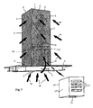
- FIG. 1 there is an extractor hood according to the invention from a screen 1 and a chimney 2.
- the screen has on its underside a suction opening 3, namely a horizontal large-area suction surface and carries control buttons 4 on its front.
- the fireplace is cuboid with rectangular or square cross-section, with rectangular chimney walls in the form of panels 5, at least some of which are lattice panels. These panels are held in a frame 6, which as vertical parts Has housing edge rails 7 and as horizontal parts at the lower end Has bottom rails 8 and upper rails 9 at the upper end.
- the chimney contains, as shown in FIG. 2, exchangeable in the air duct tract emanating from the screen 1 a fat filter 10 and a carbon filter 11, further one - in Fig.
- Blower section 14 comprising suction-side opening, to which An air line 15 via an opening on the pressure side that is not visible in the drawing connected to an extractor hood via an air duct installation leads to a wall box that takes the air out of the room.
- the Blower section 14 includes an electric motor and a compressor.
- extractor hood has the front panel in its grille a decor 16, here in the form of a tendril pattern.
- the cuboid housing 12 is on one (Fig. 1) or more sides, in addition to the downward opening 13, each with another Provided suction opening 17 which is cut one of its walls and over which the fan sucks air from the interior of the fireplace 2 and additionally in the air line 15 presses.
- the suction opening 17 can be on one or more the housing walls are formed, have any shape and with a filter, for. B. a grease filter or the like. It is especially with an island hood advantageous if two suction openings 17 face each other on the housing.
- the kitchen on the one hand, rising from the stove through the suction opening 3 of the hood screen 1 Air 18 and on the other hand sucked off through the grid panels 5 kitchen air 19.
- the kitchen air 19 consists to a large extent also of air from the cooktop rises, but flows past the hood screen.
- the kitchen air 19 penetrates, as shown in FIG. 2, the respective grid panel 5 and one behind this arranged plate-shaped filter cassette 22, from which the air over as well as through the suction opening 17 from the blower section 14 and then is carried away with the exhaust air through the exhaust air line 15.
- the large-area filter cassette 22 enables a very effective air filtering. It can be a dust and grease filter, a carbon filter or a stratification of these two filters.
- Fig. 1 only a single suction opening 17 is shown in the housing 12, such suction openings are, however, on all side surfaces and / or on the Top of the housing 12 possible.
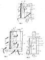
- Fig. 3 shows a modification in that the dome 24 by a Chamber 31 separating partition 32 is replaced, the two additional fans 33 carries, which controllably transport the kitchen air 19 into the exhaust duct 15.
- the grid 26, which is integrated in the panel here in comparison to FIG. 2, and the 3 are used to distribute the suction power between air flows 18 and 19.
- Fig. 4 illustrates a further modified embodiment in which the fan section 14 outside the actual extractor hood, namely in the course of the exhaust duct 15, for example in the wall box.
- the air duct is divided into modules 36 and one of the modules is the grid panel 5, the dome 24 and the additional blower 33 Kitchen room air 19 initiated.
- the kitchen air is 19 not passed through a filter arranged on the grid panel 5, but can be present in the modules 36 filter in a manner not shown.
- Blower section 14 located outside the chimney can be another Suction opening analogous to the suction opening 17 of FIG. 1 to be present on Extract room air from the location of the blower section.
- Filter cartridges as illustrated for example in Fig. 2 and 3 as plates need to be cleaned and / or replaced with new filter cartridges be interchangeable. Depending on the load, such an exchange can, for example fall due after a few months. Even with airtight wall panels occasional cleaning is desirable.
- 5 and 6 show a construction, which facilitates the exchange of the filters or panels in that the Wall panels 5 taken out of the frame 6 in total and again can be inserted. There are various options for this, in Figs 5 and 6 illustrates the possibility that the panel in question 5, the one Grid panel or also a plate panel, for example a decorative glass plate can, in a formed on the bottom rail 8 lower groove 38 and one on the upper rail 9 formed upper channel 39 is used in each case.
- a leaf spring 40 is installed, which presses the panel 5 downwards.
- the gutter depth the upper groove 39 is greater than the groove depth of the lower groove 38, and by pushing the panel 5 upward against the compressive force of the spring 40
- the lower end of the panel 5 becomes the lower groove 38 lifted out and can be swung forward and out of the frame 6 be removed. So far on the panel 5 filter cassettes or other filter plates mounted, they can then be removed and replaced. The The panel itself can be cleaned without difficulty. Finally it will be back used in the frame 6.
- the handle 41 is designed so that it can also take on additional functions can, for example, as a hanger for towels and devices.
- the leaf spring 40 may also be missing Panel 5 will then be in the operating position of the extractor hood Weight held in the lower groove 38.
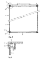
- Fig.n 7 and 8 show schematically and with an open front, one each modified extractor hood, namely a recirculation hood, the filtered and returns cleaned air 45 to the kitchen room. It again shows the umbrella 1, the suction opening 3, the blower section 14 and above the air line 15.
- the hoods of Fig.n 7 and 8 give the sucked air 18 and (Fig. 7) 19 which in Shape of arrows is indicated, filtered and optionally (Fig. 7) by a Fragrance dispenser 60 refined to the interior, and that is the air through Air deflection bends 61 transported to large-area filter cassettes 62, each form an entire chimney wall and from perforated plates 63 for example Stainless steel.
- the available large area of the filter cassettes has the consequence that at every point the approaching air, which is on a large flow cross-section, only relatively slowly through the filter cassette flows through and can therefore be filtered very effectively there.
- one of the chimney wall panels 5 is comparable to FIG. 2 Suction surface for the kitchen air 19 and another panel 5 'an air discharge surface; 8, both opposite wall panels are air discharge surfaces.
- the filter chimney walls the main components of which the filter cassettes 62 and the perforated plates 63 are, as a whole, in the Chimney frame interchangeably hung, in this embodiment clipped in, on the one hand pins 64, on the other hand spring clips 65 and corresponding complementary parts serve in the permanently installed fireplace frame.
- the filter cartridges are carbon filters that are identified in the drawing by dot hatching are. However, this is not to be understood as restrictive.
- the filters can be carbon filter cartridges, Charcoal mats and general filters of all kinds, possibly supplemented through grease filters. You can use a simple tool in their Bracket raised and then removed.
- the perforated sheets can for example also made of aluminum or in simple versions made of plastic consist.
- a filter saturation indicator is used to monitor the filter status 66, which are determined on the basis of a pressure meter 67 with increasing Filter impenetrability of increasing pressure in the chamber of the hood, that the next filter change is due (Fig. 7).
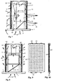
- Figs. 11 and 12 show a step plate 69 with blow-out holes 70, which are directed upwards are. 12 there is an increased air discharge in the upper region of the fireplace thereby achieved that through larger blow-out holes 70 there is a larger flow cross-section is available as in the lower part of the fireplace.
- the chimney wall has a fold-out wall with a grille 71. Behind the grille there is a replaceable (not shown) filter cassette.
- FIGS. 14 to 19 illustrate various possibilities, for example the walls of the chimney of the extractor hood partly with filter cassettes and partly with wall panels, which can be decorative panels, for example.
- Fig. 14 shows a wall hood, the chimney is open at the back because it is there leaning against the wall of the room. All three other chimney walls are with filter cassettes busy. 15, only the side walls are covered with filter cartridges and the front wall is formed by a decorative panel; while this decorative panel The filter cartridges are inserted and therefore not easily interchangeable with their brackets clipped in for replacement, cleaning, etc. and thus easy to remove and reinsert.
- Fig. 15 shows a constellation that is particularly for one between furniture located extractor hood is suitable, with side wall panels and a front Filter cassette;
- Fig. 17 shows an example of the possibility of filtering only laterally To release air.
- the Fig.n 18 and 19 show possibilities for island hoods, that is are not installed on the wall.
- Fig. 18 there are filter cartridges all around used, in Fig. 19 only on two opposite side surfaces.
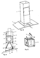
- the door 73 can be different Serve purposes, for example to replace filter cartridges. Farther it can be used to match a drawer module located behind it accessible to the blower section 14 designed as a separate module make and lock again.
- a corresponding extractor hood is with their inner parts shown in Figs. 21 and 22 described later. But Even with permanently installed interior parts, the door 73 can be useful for access to facilitate the engine and control for service work, etc. especially with extractor hoods that are complete with kitchen cabinets etc. are converted. This may result in an expansion of the entire device be avoided for repair.
- the door is of course not on the one shown Limited execution. In particular, it can cover the entire front of the fireplace Claim, it can be a flap that can be pivoted about any axis or it can also be a releasable fixation means such as clips on the fireplace Wall plate.
- Fig.n 21 and 22 show the extractor hood, in which the fan section 14 represents a drawer module, which is indicated by the indicated door 73 of the Chimney frame 6 insertable on rails 74 and inside (in the drawing Fixing screws (not shown) can be fixed.
- a Control box 75 in the built in the fireplace frame 6 in this embodiment Fastening section used and fastened there at 76. in the Chimney frames 6 are plugs, not shown, for detachable at suitable points The removable module is attached.
- the control box 75 is via cables and plugs (not visible in FIG. 21) to the power and control lines connected to the hood.
- the door 73 closed.
- the rails in the drawer can also be used be arranged at the top and the module be hung there.
- FIG. 21 A further detail is shown in FIG. 21, namely an intermediate frame 79, which represents another detachable module and in one at this Embodiment formed below the chimney 2 at the bottom of the frame 6
- Mounting groove 80 can be inserted or clipped with a rib 81 and on the opposite side can be screwed with the help of a mounting flange 82.
- the intermediate frame 79 has another at its sloping lower edge Mounting flange on that of the attachment of the screen 1 in an oblique arrangement serves. As a result, the inclined hood screen assembly is useful in some cases possible.
- 23 to 26 illustrate embodiments of the invention Extractor hood, which is characterized by different fireplace designs award;
- 23 is an exhaust hood with kitchen room suction on upper end of one of the wall panels;
- Fig. 24 is a recirculation hood with additional Kitchen room extraction through special air holes in the fireplace, the same 25 and FIG. 26 such a circulating air hood with large-area lattice panels, which also have a decorative design.
- FIGS. 27 to 29 show variants to illustrate the possible ones Variety of constructions according to the invention.
- Fig. 27 shows an extraction of kitchen air via one in one of the Wall panels 5 attached suction opening, which is screwed on Cover plate 85 is covered.
- a ring arrangement of Holes 86 which are in turn covered by an identical ring arrangement having rotary plate 87.
- the flow cross section set By rotating the rotary plate 87, the flow cross section set, the arrangement thus fulfills the function of the grid 26 of Fig. 2.
- a filter cassette is attached can be replaced after unscrewing the plate 85.
- Fig. 28 shows in section an embodiment of the panel 5, with a cross hinge 89 extending therethrough and a hinged opening provided with air holes Part 90 of the panel, on the inside of the chimney in trough-shaped rails that are on its side edges and its lower edge are formed, the carbon filter 12 is inserted interchangeably from above.
- the panel 5 shown in Fig. 29 has a frame 92 in which the filter cartridge 22 is used with a combined fat and carbon filter.
- the frame 92 forms on three sides rails 93 and is open on a fourth side 94, so that there Filter cartridge can be pushed in and out.
Priority Applications (1)
| Application Number | Priority Date | Filing Date | Title |
|---|---|---|---|
| DE20122340U DE20122340U1 (de) | 2000-03-15 | 2001-02-12 | Dunstabzugshaube |
Applications Claiming Priority (2)
| Application Number | Priority Date | Filing Date | Title |
|---|---|---|---|
| DE20005154U | 2000-03-15 | ||
| DE20005154U DE20005154U1 (de) | 2000-03-15 | 2000-03-15 | Dunstabzugshaube |
Publications (1)
| Publication Number | Publication Date |
|---|---|
| EP1134501A1 true EP1134501A1 (fr) | 2001-09-19 |
Family
ID=7939067
Family Applications (1)
| Application Number | Title | Priority Date | Filing Date |
|---|---|---|---|
| EP01103258A Withdrawn EP1134501A1 (fr) | 2000-03-15 | 2001-02-12 | Hotte aspirante de buée |
Country Status (2)
| Country | Link |
|---|---|
| EP (1) | EP1134501A1 (fr) |
| DE (1) | DE20005154U1 (fr) |
Cited By (9)
| Publication number | Priority date | Publication date | Assignee | Title |
|---|---|---|---|---|
| WO2003072222A2 (fr) * | 2002-02-27 | 2003-09-04 | BSH Bosch und Siemens Hausgeräte GmbH | Systeme de filtrage pour hotte aspirante |
| EP1522793A1 (fr) | 2003-10-08 | 2005-04-13 | bulthaup GmbH & Co KG | Hotte d'aspiration de fumée |
| CN100376842C (zh) * | 2003-02-25 | 2008-03-26 | 汤健中 | 抽油烟机烟道里的隔热消声装置 |
| US7445546B2 (en) | 2002-12-19 | 2008-11-04 | Bsh Bosch Und Slemens Hausgeraete Gmbh | Housing for an extractor hood and ventilator housing |
| EP2090835A3 (fr) * | 2008-02-14 | 2011-05-04 | Franke Futurum Aktiebolag | Hotte aspirante |
| CN108019803A (zh) * | 2017-11-27 | 2018-05-11 | 佛山市云米电器科技有限公司 | 一种具有卷吸效应的非平面式抽油烟机 |
| DE102017100819A1 (de) | 2017-01-17 | 2018-07-19 | Miele & Cie. Kg | Dunstabzugshaube und Verfahren zum Betreiben |
| CN109695906A (zh) * | 2017-10-24 | 2019-04-30 | 宁波方太厨具有限公司 | 吸油烟机 |
| EP2827067B1 (fr) * | 2013-07-15 | 2020-07-08 | BSH Hausgeräte GmbH | Hotte aspirante |
Families Citing this family (15)
| Publication number | Priority date | Publication date | Assignee | Title |
|---|---|---|---|---|
| DE10063374A1 (de) * | 2000-12-19 | 2002-06-20 | Bsh Bosch Siemens Hausgeraete | Dunstabzugshaube für Kochstellen mit einer oder mehreren wendbaren Dekorplatten |
| DE10103405B4 (de) * | 2001-01-09 | 2006-06-08 | HiServ Gebäudedienstleistungen GmbH | Absaugeinrichtung für eine Küchenanordnung und Küchenanordnung |
| EP1482248A3 (fr) * | 2003-05-30 | 2008-09-17 | OY Halton Group Limited | Système de ventilation modulaire |
| DE102004049979A1 (de) * | 2004-10-14 | 2006-04-20 | Exklusiv-Hauben Gutmann Gmbh | Dunstabzugshaube |
| DE102007019518A1 (de) * | 2007-04-25 | 2008-10-30 | BSH Bosch und Siemens Hausgeräte GmbH | Dunstabzugshaube |
| US8171483B2 (en) | 2007-10-20 | 2012-05-01 | Citrix Systems, Inc. | Method and system for communicating between isolation environments |
| DE102007059786A1 (de) * | 2007-12-12 | 2009-06-18 | BSH Bosch und Siemens Hausgeräte GmbH | Dunstabzugsvorrichtung |
| DE102008011020A1 (de) * | 2008-02-25 | 2009-08-27 | BSH Bosch und Siemens Hausgeräte GmbH | Dunstabzugsvorrichtung |
| DE102008023311A1 (de) | 2008-05-13 | 2009-11-19 | BSH Bosch und Siemens Hausgeräte GmbH | Umluftweiche sowie Verfahren zum Montieren einer Umluftweiche |
| DE102008041002A1 (de) * | 2008-08-05 | 2010-02-11 | BSH Bosch und Siemens Hausgeräte GmbH | Dunstabzugsvorrichtung sowie Verfahren zur Herstellung einer solchen Dunstabzugsvorrichtung |
| DE102010000659A1 (de) * | 2010-03-05 | 2011-09-08 | Manfred H. Langner | Abluftkamin für eine Ablufthaube |
| ITRN20110040A1 (it) * | 2011-05-31 | 2012-12-01 | Indesit Co Spa | Cappa |
| DE102011108076A1 (de) * | 2011-07-21 | 2013-01-24 | Ladwig Feinwerktechnik Gmbh | Absaugvorrichtung |
| DE102012213097A1 (de) * | 2012-07-25 | 2014-02-13 | BSH Bosch und Siemens Hausgeräte GmbH | Dunstabzugsvorrichtung |
| CN106678914B (zh) | 2016-12-27 | 2019-07-30 | 美的集团股份有限公司 | 油烟分离装置及排烟装置 |
Citations (3)
| Publication number | Priority date | Publication date | Assignee | Title |
|---|---|---|---|---|
| FR2334061A1 (fr) * | 1975-12-04 | 1977-07-01 | Electrolux Ab | Hotte aspirante pour cuisine |
| US5220910A (en) * | 1990-01-31 | 1993-06-22 | Halton Oy | Device and method for ventilation |
| DE29916895U1 (de) | 1999-09-24 | 2000-01-13 | Buercher Friedrich | Rahmen aus Profilstäben, und hiermit herstellbare Luftleitungselemente wie eine Dunstabzugshaube und ein Mauerkasten mit Schalldämmung |
-
2000
- 2000-03-15 DE DE20005154U patent/DE20005154U1/de not_active Expired - Lifetime
-
2001
- 2001-02-12 EP EP01103258A patent/EP1134501A1/fr not_active Withdrawn
Patent Citations (3)
| Publication number | Priority date | Publication date | Assignee | Title |
|---|---|---|---|---|
| FR2334061A1 (fr) * | 1975-12-04 | 1977-07-01 | Electrolux Ab | Hotte aspirante pour cuisine |
| US5220910A (en) * | 1990-01-31 | 1993-06-22 | Halton Oy | Device and method for ventilation |
| DE29916895U1 (de) | 1999-09-24 | 2000-01-13 | Buercher Friedrich | Rahmen aus Profilstäben, und hiermit herstellbare Luftleitungselemente wie eine Dunstabzugshaube und ein Mauerkasten mit Schalldämmung |
Cited By (13)
| Publication number | Priority date | Publication date | Assignee | Title |
|---|---|---|---|---|
| WO2003072222A2 (fr) * | 2002-02-27 | 2003-09-04 | BSH Bosch und Siemens Hausgeräte GmbH | Systeme de filtrage pour hotte aspirante |
| WO2003072222A3 (fr) * | 2002-02-27 | 2004-03-11 | Bsh Bosch Siemens Hausgeraete | Systeme de filtrage pour hotte aspirante |
| CN100430653C (zh) * | 2002-02-27 | 2008-11-05 | Bsh博施及西门子家用器具有限公司 | 排烟罩及其过滤装置 |
| US7445546B2 (en) | 2002-12-19 | 2008-11-04 | Bsh Bosch Und Slemens Hausgeraete Gmbh | Housing for an extractor hood and ventilator housing |
| CN100376842C (zh) * | 2003-02-25 | 2008-03-26 | 汤健中 | 抽油烟机烟道里的隔热消声装置 |
| EP1522793A1 (fr) | 2003-10-08 | 2005-04-13 | bulthaup GmbH & Co KG | Hotte d'aspiration de fumée |
| EP2090835A3 (fr) * | 2008-02-14 | 2011-05-04 | Franke Futurum Aktiebolag | Hotte aspirante |
| EP2827067B1 (fr) * | 2013-07-15 | 2020-07-08 | BSH Hausgeräte GmbH | Hotte aspirante |
| DE102017100819A1 (de) | 2017-01-17 | 2018-07-19 | Miele & Cie. Kg | Dunstabzugshaube und Verfahren zum Betreiben |
| DE102017100819B4 (de) | 2017-01-17 | 2020-06-18 | Miele & Cie. Kg | Dunstabzugshaube und Verfahren zum Betreiben |
| CN109695906A (zh) * | 2017-10-24 | 2019-04-30 | 宁波方太厨具有限公司 | 吸油烟机 |
| CN109695906B (zh) * | 2017-10-24 | 2024-02-20 | 宁波方太厨具有限公司 | 吸油烟机 |
| CN108019803A (zh) * | 2017-11-27 | 2018-05-11 | 佛山市云米电器科技有限公司 | 一种具有卷吸效应的非平面式抽油烟机 |
Also Published As
| Publication number | Publication date |
|---|---|
| DE20005154U1 (de) | 2000-06-08 |
Similar Documents
| Publication | Publication Date | Title |
|---|---|---|
| EP1134501A1 (fr) | Hotte aspirante de buée | |
| DE102008033792A1 (de) | Umluftmodul und Dunstabzugsvorrichtung | |
| EP1239226B1 (fr) | Hotte aspirante | |
| DE19645096A1 (de) | Luftreinigungsgerät | |
| WO2005100863A1 (fr) | Dispositif d'aspiration de fumees pour systeme de preparation d'aliments | |
| DE10325007A1 (de) | Abzugshaube für einen Küchenherd | |
| EP3701192A1 (fr) | Appareil combiné comprenant un dispositif d'aspiration des fumées et une table de cuisson | |
| DE102009002773A1 (de) | Dunstabzugshaube mit Abdeckungen für Luftdurchlassflächen | |
| EP2772695B1 (fr) | Hotte aspirante | |
| DE20122340U1 (de) | Dunstabzugshaube | |
| EP2210048B1 (fr) | Dispositif d'aspiration de vapeurs | |
| DE102005008373A1 (de) | Dunstabzugshaube | |
| EP2145134A1 (fr) | Hotte aspirante | |
| EP1094278A2 (fr) | Dispositif d'évacuation des fumées | |
| EP2829808B1 (fr) | Hotte aspirante | |
| DE102007061981A1 (de) | Dunstabzugsvorrichtung | |
| EP2112437B1 (fr) | Dispositif d'aspiration de vapeur doté d'une tôle de guidage des vapeurs | |
| DE102004043069A1 (de) | Dunstabzugshaube | |
| EP0943871B1 (fr) | Hotte d'évacuation de fumée pour cuisine | |
| DE102018119698A1 (de) | Dunstabzugssystem für Kochfelder | |
| EP0716269A1 (fr) | Revêtement amovible pour intérieur de fours | |
| DE102007060802A1 (de) | Dunstabzugshaube, Filter für Dunstabzugshaube sowie diesbezügliches Verfahren | |
| EP2542837A1 (fr) | Cheminée d'évacuation d'air pour chapeau d'évacuation d'air | |
| DE1929701U (de) | Dunstabzugshaube. | |
| DE102019202065A1 (de) | Dunstabzugshaube mit Filterelement |
Legal Events
| Date | Code | Title | Description |
|---|---|---|---|
| PUAI | Public reference made under article 153(3) epc to a published international application that has entered the european phase |
Free format text: ORIGINAL CODE: 0009012 |
|
| AK | Designated contracting states |
Kind code of ref document: A1 Designated state(s): AT BE CH CY DE DK ES FI FR GB GR IE IT LI LU MC NL PT SE TR |
|
| AX | Request for extension of the european patent |
Free format text: AL;LT;LV;MK;RO;SI |
|
| 17P | Request for examination filed |
Effective date: 20020319 |
|
| AKX | Designation fees paid |
Free format text: AT BE CH CY DE DK ES FI FR GB GR IE IT LI LU MC NL PT SE TR |
|
| 17Q | First examination report despatched |
Effective date: 20031009 |
|
| GRAP | Despatch of communication of intention to grant a patent |
Free format text: ORIGINAL CODE: EPIDOSNIGR1 |
|
| STAA | Information on the status of an ep patent application or granted ep patent |
Free format text: STATUS: THE APPLICATION IS DEEMED TO BE WITHDRAWN |
|
| 18D | Application deemed to be withdrawn |
Effective date: 20050210 |