EP1128470A1 - Contact à déplacement d'isolation et son procédé de fabrication - Google Patents
Contact à déplacement d'isolation et son procédé de fabrication Download PDFInfo
- Publication number
- EP1128470A1 EP1128470A1 EP01101171A EP01101171A EP1128470A1 EP 1128470 A1 EP1128470 A1 EP 1128470A1 EP 01101171 A EP01101171 A EP 01101171A EP 01101171 A EP01101171 A EP 01101171A EP 1128470 A1 EP1128470 A1 EP 1128470A1
- Authority
- EP
- European Patent Office
- Prior art keywords
- wire
- portions
- edges
- contact
- terminal fitting
- Prior art date
- Legal status (The legal status is an assumption and is not a legal conclusion. Google has not performed a legal analysis and makes no representation as to the accuracy of the status listed.)
- Withdrawn
Links
Images


Classifications
-
- H—ELECTRICITY
- H01—ELECTRIC ELEMENTS
- H01R—ELECTRICALLY-CONDUCTIVE CONNECTIONS; STRUCTURAL ASSOCIATIONS OF A PLURALITY OF MUTUALLY-INSULATED ELECTRICAL CONNECTING ELEMENTS; COUPLING DEVICES; CURRENT COLLECTORS
- H01R43/00—Apparatus or processes specially adapted for manufacturing, assembling, maintaining, or repairing of line connectors or current collectors or for joining electric conductors
- H01R43/01—Apparatus or processes specially adapted for manufacturing, assembling, maintaining, or repairing of line connectors or current collectors or for joining electric conductors for connecting unstripped conductors to contact members having insulation cutting edges
-
- H—ELECTRICITY
- H01—ELECTRIC ELEMENTS
- H01R—ELECTRICALLY-CONDUCTIVE CONNECTIONS; STRUCTURAL ASSOCIATIONS OF A PLURALITY OF MUTUALLY-INSULATED ELECTRICAL CONNECTING ELEMENTS; COUPLING DEVICES; CURRENT COLLECTORS
- H01R4/00—Electrically-conductive connections between two or more conductive members in direct contact, i.e. touching one another; Means for effecting or maintaining such contact; Electrically-conductive connections having two or more spaced connecting locations for conductors and using contact members penetrating insulation
- H01R4/24—Connections using contact members penetrating or cutting insulation or cable strands
- H01R4/2416—Connections using contact members penetrating or cutting insulation or cable strands the contact members having insulation-cutting edges, e.g. of tuning fork type
- H01R4/2445—Connections using contact members penetrating or cutting insulation or cable strands the contact members having insulation-cutting edges, e.g. of tuning fork type the contact members having additional means acting on the insulation or the wire, e.g. additional insulation penetrating means, strain relief means or wire cutting knives
- H01R4/2466—Connections using contact members penetrating or cutting insulation or cable strands the contact members having insulation-cutting edges, e.g. of tuning fork type the contact members having additional means acting on the insulation or the wire, e.g. additional insulation penetrating means, strain relief means or wire cutting knives the contact members having a channel-shaped part, the opposite sidewalls of which comprise insulation-cutting means
Definitions
- the present invention relates to an insulation-displacement terminal fitting and to a method for producing the same.
- a known insulation-displacement terminal fitting is disclosed in Japanese Unexamined Patent Publication No. 8-241740.
- This terminal fitting includes inward facing blade portions formed on a pair of side walls.
- the blade portions are formed by embossing portions of the side walls inwardly in such a manner as to project in V-shape when viewed in a direction in which a wire is pushed.
- a resin coating of the wire pushed in between the blade portions are cut by the edges of the V-shaped blade portions and a core thereof is brought into contact with contact edges at the projecting ends of the blade portions.
- a pair of V-shaped edges are generally inclined to come close to each other in a wire pushing direction as a guiding means for guiding a wire into a proper position between the blade portions.
- this angle is small, the wire may be pushed in between contact edges of the blade portions only by being elastically deformed without having its resin coating cut and the blade portions and a core of the wire may not be in contact with each other.
- an object of the present invention is to securely cut a resin coating of a wire without impairing a function of guiding the wire to between blade portions.
- an insulation displacement terminal fitting to be connected with a wire, comprising at least one pair of blade portions provided at side walls thereof for connection with the wire,
- the blade portions are formed to project in substantially V-shape when viewed in a pushing direction of the wire by bending or embossing portions of the side walls inwardly.
- the hooking portions project toward the wire being pushed in between the blade portions.
- the cutting edges are substantially V-shaped.
- an insulation displacement terminal fitting to be connected with a wire by pushing the wire in between a pair of blade portions in a direction normal to its longitudinal axis, in which terminal fitting the blade portions are formed to project in V-shape when viewed in a pushing direction of the wire by bending portions of side walls inwardly, projecting ends of the blade portions act as contact edges, a resin coating of the wire pushed in between the blade portions is cut open by V-shaped edges of the blade portions to bring a core of the wire into contact with the contact edges, and the V-shaped edges are inclined in such directions as to guide the wire from the side walls to the contact edges when viewed from the longitudinal direction of the wire, wherein hooking portions projecting toward the wire being pushed in between the blade portions are formed at ends of the V-shaped edges toward the contact edges.
- the hooking portions projecting toward the wire being pushed in are formed at the ends of the V-shaped edges toward the contact edges, the resin coating of the wire can be securely cut by the hooking portions even if the angle of inclination of the V-shaped edges are made smaller to facilitate guiding of the wire.
- both the function of guiding the wire from the side walls toward the contact edges and the function of securely cutting the resin coating can be realized.
- each hooking portion has a pointed shape of a substantially right angle or acute angle when viewed in the longitudinal direction of the wire or of the terminal fitting.
- the hooking portions have a pointed shape of a substantially right angle or acute angle, they can securely bite in the resin coating to cut it open.
- each hooking portion is so formed as to be substantially continuous and in flush with the corresponding contact edge when viewed in the longitudinal direction of the wire.
- each hooking portion is so formed as to be continuous and in flush with the contact edge, an embossing step for causing the hooking portion to project inwardly or outwardly with respect to the contact edge is unnecessary.
- each hooking portion is so formed as to be continuous with and arranged at an obtuse angle with respect to the cutting edges of the blade portions.
- depressed portions of valley-shaped areas of the side walls which will become the preferably substantially V-shaped cutting edges are punched or cut out to have an arcuate or trapezoidal shape in a development before the side walls are bent, and the hooking portions are formed by bending or embossing the arcuate or trapezoidal depressed portions.
- a punching die can be more easily formed as compared to a case where the hooking portions are punched out preferably in V-shape.
- an insulation displacement terminal fitting in particular according to the invention or an embodiment thereof, to be connected with a wire, comprising the following steps:
- the method further comprises the following steps:
- Insulation-displacement terminal fittings T of this embodiment are produced from chained terminals R in which a multitude of substantially plate-shaped terminal materials S stamped or cut out in a specified shape are connected by a carrier C, and are formed by bending, deforming, and/or embossing the terminal materials S detached from the carrier C into a specified configuration or shape.
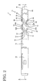
- left side in FIGS. 2 and 3 is referred to as front and vertical direction is based on FIGS. 3 to 5 in this embodiment.
- the formed insulation-displacement terminal fitting T is first described.
- the insulation-displacement terminal fitting T is substantially narrow along forward and backward or longitudinal directions as a whole.
- a substantially front half thereof is a fitting portion 10 as a connection means with a mating male terminal fitting (not shown).
- the fitting portion 10 preferably has, as a whole, a substantially rectangular box-shape having open front and rear end faces, and a substantially triangularly bent elastic contact piece 10A is provided in the fitting portion 10.
- a substantially rear half of the insulation displacement terminal fitting T is a connecting portion 11 to be connected with a wire W.
- the connecting portion 11 is comprised of blade portions 12 and crimping pieces 16.
- Corresponding left and right blade portions 12 make pairs, and two pairs are provided one after the other in this embodiment.
- the respective blade portions 12 are formed by bending, deforming and/or embossing portions of a pair of side walls 14 extending at an angle different from 0° or 180°, preferably substantially normal or upward from preferably the left and right ends of a bottom wall 13 preferably in substantially V-shape when viewed from above (when viewed in a pushing or inserting direction D of a wire W during insulation displacement).
- the upper edge and the projecting edge of each blade portion 12 are referred to as a cutting edge 12A, preferably a substantially V-shaped edge 12A and a contact edge 12B, respectively.
- the pair of substantially V-shaped edges 12A are inclined or slanted to come closer or converge to each other so as to guide the wire W from the side walls 14 toward the contact edges 12B or a central portion of the terminal fitting T, and the wire W is substantially guided to a proper contact position between the blade portions 12 by the inclinations of the left and right V-shaped edges 12A.
- the contact edges 12B are substantially parallel to vertical direction (parallel to the pushing or inserting direction D of the wire W).
- the wire W is pushed or inserted in between the above blade portions substantially along the insertion direction D for connection while being oriented such that its longitudinal axis substantially extends in forward and backward or longitudinal directions.
- the wire W is guided to a center position (proper contact position) with respect to transverse direction by the inclinations of the V-shaped edges 12A, an insulation coating Wa, preferably a resin coating Wa thereof is cut by the V-shaped edges 12A, and contact edges 12B thereof bite in the cuts made in the resin coating Wa to come into contact with a core Wb.
- the V-shaped edges 12A of the blade portions 12 are inclined with respect to the pushing direction of the wire W in order to guide the wire W to the proper contact position.
- a guiding function is improved.
- such a steep inclination disadvantageously reduces a function of cutting the resin coating Wa by the V-shaped edges 12A.
- the angle of inclination of the V-shaped edges is made larger (if the inclination is moderated in FIG. 4), the wire W is likely to get caught on the V-shaped edges 12A to thereby degrade the guiding function although the resin coating Wa is more easily cut.
- a hooking portion 15 is formed at an end (leading upper end of each blade portion 12) of each V-shaped edge 12A toward the contact edge 12B or in a portion of the cutting edge 12 between the cutting or substantially V-shaped edge 12A and the contact edge 12B as a means for securely cutting the resin coating Wa without impairing the guiding function.
- the hooking portion 15 is so formed as to project toward the wire W being pushed in between the blade portions 12.
- the hooking portion 15 When viewed in the longitudinal direction of the wire W, the hooking portion 15 has a pointed shape of a substantially right angle formed between a vertical line 15b and a horizontal line 15a.
- the vertical line 15b contouring the hooking portion 15 is substantially continuous and in flush with the corresponding contact edge 12B, whereas the horizontal line 15a is substantially continuous with the corresponding inclined V-shaped edge 12A at an obtuse angle thereto, the obtuse angle being preferably comprised between 100° and 170°, more preferably between 120° and 150°.
- the crimping pieces 16 of the connecting portion 11 are so formed as to extend upward from the left and right ends of the bottom wall 13 behind the blade portions 12, and are crimped into connection with the wire W mounted between the blade portions 12.
- Slits 17 are formed along boundaries between the bottom wall 13 and the side walls 14 over a forming area of the respective blade portions 12.
- the blade portions 12 can be embossed into V-shape without deforming the bottom wall 13.
- the respective terminal materials S separated from the carrier C in the chained terminals R are bent along specified folds (no reference numerals are given, but shown in broken line in FIG. 6).
- the blade portions 12 are formed by bending portions of the side walls 14 substantially in V-shape.
- This shape is a "substantially V-shaped” as a whole and a depressed portion of this V-shape is "arcuate" as shown in FIG. 7(A) or "trapezoidal" as shown in FIG. 7(B).
- the V-shaped edge 12 is substantially straight from the side wall 14 to the contact edge 12B when viewed in the longitudinal direction of the wire W, i.e. no hooking portion 15 is formed.
- the hooking portion 15 is formed by embossing the terminal material S having the "arcuate” or “trapezoidal" depressed portion as in this embodiment.
- a punching die (not shown) for forming the V-shaped edges 12A and the hooking portion 15 when the terminal materials S are punched out.
- the punching die having such a shape is unlikely to be abraded as compared to a case where the leading end of the pressing die is pointed.
- the wire W When being pushed in between the left and right blade portions 12 from above, the wire W comes into contact with the V-shaped edges 12A. At this time, even if the wire W is transversely displaced from the center between the blade portions 12, the position thereof is corrected to the center by the inclinations of the transversely symmetrical V-shaped edges 12A.
- the insulation or resin coating Wa is substantially cut by the V-shaped edges 12A as the wire W is further pushed in.
- the resin coating Wa may only slide on the V-shaped edges 12A and the wire W may be consequently held between the contact edges 12B while being deformed without the resin coating Wa being cut.
- the hooking portions 15 obliquely projecting from below toward the wire W are formed at the inner ends of the V-shaped edges 12A in this embodiment, they bite in the resin coating Wa to cut it open. Further, since the hooking portions 15 provided between the substantially V-shaped edge 12A and the contact edge 12B preferably have a pointed shape preferably of a substantially right angle, it can be securely pierced into the resin coating Wa.
- the hooking portions 15 projecting toward the wire W being pushed in are formed at the ends of the V-shaped edges 12A toward the contact edges 12B in this embodiment, the resin coating Wa of the wire W can be securely cut by the hooking portions 15 even if the angle of inclination of the V-shaped edges 12A is made smaller to facilitate guiding of the wire W.
- both the function of guiding the wire W from the side walls 14 toward the contact edges 12B and the function of securely cutting the resin coating Wa can be realized.
- the hooking portions 15 have a pointed shape preferably of a substantially right angle, they can securely bite in the resin coating Wa to cut it open even if coming into contact with the resin coating Wa in a direction oblique to the wire pushing direction.
- each hooking portion 15 is formed such that the vertical line 15b contouring the hooking portion 15 is continuous and in flush with the contact edge 12B when viewed in the longitudinal direction of the wire W, the blade portion 12 can be formed only be embossing a portion of the side wall 14 into V-shape, obviating the need for an embossing step for causing the hooking portion 15 to project inwardly or outwardly with respect to the contact edge 12B. It should be noted that no special processing is necessary since the horizontal line 15a of the hooking portion 15 substantially continuous with the V-shaped edge 12A can be formed in the step of punching the terminal material S out by a press.
- the punching die can be more easily formed as compared to a case where the hooking portions 15 are punched into a V-shape.
Applications Claiming Priority (2)
| Application Number | Priority Date | Filing Date | Title |
|---|---|---|---|
| JP2000043731A JP2001237002A (ja) | 2000-02-22 | 2000-02-22 | 圧接端子金具 |
| JP2000043731 | 2000-02-22 |
Publications (1)
| Publication Number | Publication Date |
|---|---|
| EP1128470A1 true EP1128470A1 (fr) | 2001-08-29 |
Family
ID=18566600
Family Applications (1)
| Application Number | Title | Priority Date | Filing Date |
|---|---|---|---|
| EP01101171A Withdrawn EP1128470A1 (fr) | 2000-02-22 | 2001-01-23 | Contact à déplacement d'isolation et son procédé de fabrication |
Country Status (3)
| Country | Link |
|---|---|
| US (1) | US6416347B2 (fr) |
| EP (1) | EP1128470A1 (fr) |
| JP (1) | JP2001237002A (fr) |
Families Citing this family (3)
| Publication number | Priority date | Publication date | Assignee | Title |
|---|---|---|---|---|
| US7413465B2 (en) * | 2006-04-12 | 2008-08-19 | Illinois Tool Works, Inc. | Insulation displacement system |
| US7347717B2 (en) * | 2006-04-12 | 2008-03-25 | Illinois Tool Works | Insulation displacement system |
| US7396264B2 (en) * | 2006-05-02 | 2008-07-08 | K.S. Terminals, Inc. | Electrical-tap connector |
Citations (5)
| Publication number | Priority date | Publication date | Assignee | Title |
|---|---|---|---|---|
| US3867005A (en) * | 1972-09-14 | 1975-02-18 | Bunker Ramo | Insulation-piercing contact member and electrical connector |
| US4040702A (en) * | 1975-06-23 | 1977-08-09 | Trw Inc. | Solderless termination system |
| GB1585345A (en) * | 1977-04-18 | 1981-02-25 | Bunker Ramo | Electrical connector having displaceable sidewall terminal element |
| EP0320310A2 (fr) * | 1987-12-11 | 1989-06-14 | Molex Incorporated | Borne à déplacement d'isolant à haute pression de contact pour câbles multibrins |
| JPH09274941A (ja) * | 1996-04-03 | 1997-10-21 | Yazaki Corp | 圧接端子 |
Family Cites Families (21)
| Publication number | Priority date | Publication date | Assignee | Title |
|---|---|---|---|---|
| USRE31132E (en) * | 1972-09-14 | 1983-01-25 | Bunker Ramo Corporation | Electrical connector and insulation-piercing contact member |
| US4210379A (en) * | 1979-03-15 | 1980-07-01 | Amp Incorporated | Modular barrier block |
| US4344664A (en) * | 1980-10-03 | 1982-08-17 | Ark-Les Corporation | Wide compliance insulation displacement terminal block |
| US4472596A (en) * | 1982-07-30 | 1984-09-18 | At&T Technologies, Inc. | Electrical connector |
| DE4015238A1 (de) * | 1990-05-10 | 1991-11-14 | Krone Ag | Anschlussleiste fuer die fernmeldetechnik |
| DE4137507A1 (de) * | 1991-11-14 | 1993-05-19 | Siemens Ag | Schneidklemme zum anschliessen eines isolierten schaltdrahtes |
| US5399098A (en) * | 1993-10-29 | 1995-03-21 | Molex Incorporated | Electrical connector and terminal therefor for mating with a blade contact |
| US5683266A (en) * | 1994-03-31 | 1997-11-04 | Bitron S.P.A. | Device and method for the mechnical and electrical connection of a terminal |
| JP2849899B2 (ja) * | 1994-06-29 | 1999-01-27 | 矢崎総業株式会社 | 圧接端子構造 |
| US6012942A (en) * | 1995-12-29 | 2000-01-11 | Volstorf; James R. | Insulation displacement contact dimple and method of manufacture |
| GB9500782D0 (en) | 1995-01-16 | 1995-03-08 | Amp Gmbh | Insulation displacement contact for multiple wire sizes |
| JPH1012291A (ja) * | 1996-06-20 | 1998-01-16 | Yazaki Corp | 圧接端子 |
| JPH1055832A (ja) * | 1996-08-08 | 1998-02-24 | Yazaki Corp | 圧接端子 |
| JP3225861B2 (ja) * | 1996-12-02 | 2001-11-05 | 住友電装株式会社 | 端子金具 |
| JP3225863B2 (ja) * | 1996-12-03 | 2001-11-05 | 住友電装株式会社 | 端子金具 |
| JP3281280B2 (ja) * | 1997-02-19 | 2002-05-13 | 矢崎総業株式会社 | 圧接端子 |
| JP3303724B2 (ja) * | 1997-05-27 | 2002-07-22 | 住友電装株式会社 | コネクタ及び、端子金具に対する電線の圧接方法 |
| JP3300259B2 (ja) * | 1997-06-06 | 2002-07-08 | 矢崎総業株式会社 | 圧接端子及び圧接端子と電線との接続方法 |
| JPH11224702A (ja) * | 1998-02-09 | 1999-08-17 | Sumitomo Wiring Syst Ltd | 圧接端子 |
| JP2000058144A (ja) * | 1998-08-10 | 2000-02-25 | Yazaki Corp | 圧接端子 |
| DE19906725C1 (de) * | 1999-02-18 | 2001-01-11 | Harting Kgaa | Leiteranschlußelement |
-
2000
- 2000-02-22 JP JP2000043731A patent/JP2001237002A/ja active Pending
-
2001
- 2001-01-23 EP EP01101171A patent/EP1128470A1/fr not_active Withdrawn
- 2001-01-31 US US09/774,837 patent/US6416347B2/en not_active Expired - Fee Related
Patent Citations (5)
| Publication number | Priority date | Publication date | Assignee | Title |
|---|---|---|---|---|
| US3867005A (en) * | 1972-09-14 | 1975-02-18 | Bunker Ramo | Insulation-piercing contact member and electrical connector |
| US4040702A (en) * | 1975-06-23 | 1977-08-09 | Trw Inc. | Solderless termination system |
| GB1585345A (en) * | 1977-04-18 | 1981-02-25 | Bunker Ramo | Electrical connector having displaceable sidewall terminal element |
| EP0320310A2 (fr) * | 1987-12-11 | 1989-06-14 | Molex Incorporated | Borne à déplacement d'isolant à haute pression de contact pour câbles multibrins |
| JPH09274941A (ja) * | 1996-04-03 | 1997-10-21 | Yazaki Corp | 圧接端子 |
Non-Patent Citations (1)
| Title |
|---|
| PATENT ABSTRACTS OF JAPAN vol. 1998, no. 02 * |
Also Published As
| Publication number | Publication date |
|---|---|
| JP2001237002A (ja) | 2001-08-31 |
| US6416347B2 (en) | 2002-07-09 |
| US20010016446A1 (en) | 2001-08-23 |
Similar Documents
| Publication | Publication Date | Title |
|---|---|---|
| US4834681A (en) | Electric contact terminal | |
| EP0632528B1 (fr) | Borne électrique avec dispositif de serre câble | |
| EP1703600A1 (fr) | Contacts en bandes et procédé de fabrication | |
| US6325679B2 (en) | Receptacle terminal and forming method of the same | |
| EP0649186B1 (fr) | Borne électrique pour sertissage à un conducteur | |
| EP1128470A1 (fr) | Contact à déplacement d'isolation et son procédé de fabrication | |
| EP1058342A1 (fr) | Organe de contact et procédé de fabrication | |
| EP1109254B1 (fr) | Contact autodénudant et son procédé de fabrication | |
| EP1128469A1 (fr) | Contact à déplacement d'isolant et son procédé de fabrication | |
| JP3685323B2 (ja) | 圧接端子金具及びその製造方法 | |
| EP1180816B1 (fr) | Contact à déplacement d'isolant | |
| EP3800750B1 (fr) | Contact électrique | |
| EP1150383B1 (fr) | Contact autodénudant | |
| JP2005032516A (ja) | 連鎖端子 | |
| EP1109255B1 (fr) | Contact à déplacement d'isolant et méthode de fabrication | |
| US20020048988A1 (en) | Press-connecting terminal | |
| EP1172888A1 (fr) | Connecteur à déplacement d'isolation | |
| EP1168504B1 (fr) | Connecteur à déplacement d'isolant | |
| EP1168503B1 (fr) | Contact à déplacement d'isolant et son procédé de fabrication | |
| JPH11288747A (ja) | 圧接結線用端子 | |
| JPH11224701A (ja) | 端子金具 | |
| JP2002141119A (ja) | 圧接端子金具 | |
| JP2002208446A (ja) | 圧接端子金具 | |
| JPH0719961U (ja) | 雌型端子 |
Legal Events
| Date | Code | Title | Description |
|---|---|---|---|
| PUAI | Public reference made under article 153(3) epc to a published international application that has entered the european phase |
Free format text: ORIGINAL CODE: 0009012 |
|
| 17P | Request for examination filed |
Effective date: 20010215 |
|
| AK | Designated contracting states |
Kind code of ref document: A1 Designated state(s): AT BE CH CY DE DK ES FI FR GB GR IE IT LI LU MC NL PT SE TR |
|
| AX | Request for extension of the european patent |
Free format text: AL;LT;LV;MK;RO;SI |
|
| STAA | Information on the status of an ep patent application or granted ep patent |
Free format text: STATUS: THE APPLICATION HAS BEEN WITHDRAWN |
|
| 18W | Application withdrawn |
Withdrawal date: 20020307 |