EP1109255B1 - Contact à déplacement d'isolant et méthode de fabrication - Google Patents
Contact à déplacement d'isolant et méthode de fabrication Download PDFInfo
- Publication number
- EP1109255B1 EP1109255B1 EP00127220A EP00127220A EP1109255B1 EP 1109255 B1 EP1109255 B1 EP 1109255B1 EP 00127220 A EP00127220 A EP 00127220A EP 00127220 A EP00127220 A EP 00127220A EP 1109255 B1 EP1109255 B1 EP 1109255B1
- Authority
- EP
- European Patent Office
- Prior art keywords
- blades
- wire
- blade portions
- cutting edges
- terminal fitting
- Prior art date
- Legal status (The legal status is an assumption and is not a legal conclusion. Google has not performed a legal analysis and makes no representation as to the accuracy of the status listed.)
- Expired - Fee Related
Links
Images


Classifications
-
- H—ELECTRICITY
- H01—ELECTRIC ELEMENTS
- H01R—ELECTRICALLY-CONDUCTIVE CONNECTIONS; STRUCTURAL ASSOCIATIONS OF A PLURALITY OF MUTUALLY-INSULATED ELECTRICAL CONNECTING ELEMENTS; COUPLING DEVICES; CURRENT COLLECTORS
- H01R4/00—Electrically-conductive connections between two or more conductive members in direct contact, i.e. touching one another; Means for effecting or maintaining such contact; Electrically-conductive connections having two or more spaced connecting locations for conductors and using contact members penetrating insulation
- H01R4/24—Connections using contact members penetrating or cutting insulation or cable strands
- H01R4/2416—Connections using contact members penetrating or cutting insulation or cable strands the contact members having insulation-cutting edges, e.g. of tuning fork type
- H01R4/2445—Connections using contact members penetrating or cutting insulation or cable strands the contact members having insulation-cutting edges, e.g. of tuning fork type the contact members having additional means acting on the insulation or the wire, e.g. additional insulation penetrating means, strain relief means or wire cutting knives
- H01R4/2466—Connections using contact members penetrating or cutting insulation or cable strands the contact members having insulation-cutting edges, e.g. of tuning fork type the contact members having additional means acting on the insulation or the wire, e.g. additional insulation penetrating means, strain relief means or wire cutting knives the contact members having a channel-shaped part, the opposite sidewalls of which comprise insulation-cutting means
Definitions
- the present invention relates to an insulation displacement terminal fitting and to a production method therefor.
- insulation displacement terminal fittings are formed by making cuts in a pair of side walls, bending cut portions inwardly substantially at right angles as blades, so that inwardly facing edges of a pair of blades act as cutting edges.
- Such insulation displacement terminal fittings are produced by applying plating to the outer surface of a planar conductive metal plate having a specified thickness, stamping out the metal plate in a specified shape having U-shaped slits in a part of wall portions, portions surrounded by the U-shaped slits becoming blades, bending the planar metal plate piece such that the wall portions stand and the blades extend inwardly to oppose cutting edges to each other.
- the opposed end surfaces of the cutting edges which are to be brought into contact with a core of a wire are fractured surfaces formed at the time of stamping-out, they are not protected by plating.
- plating has been generally applied to the fractured surfaces (opposed end surfaces). Such plating at a later stage means an increased number of operation steps, which results in higher production costs.
- insulation displacement terminal fittings which do not require plating at a later stage were developed.
- One example of such terminal fittings is disclosed in Japanese Unexamined Patent Publication No. 50(SHO)-114592.
- blade portions are formed by striking a pair of side walls to project inwardly by a press. Each blade portion is such that a V-shaped blade project from the corresponding side wall and an projecting edge of the blade serves as a contacting edge.
- the cutting edges of the V-shaped blades cut a resin coating of the wire and a thus exposed core comes into contact with the contacting edges.
- the projecting edges of the V-shaped blades which serve as contacting edges are left plated since they are formed by pushing the side walls plated before stamping-out inwardly. Thus, plating at a later stage is unnecessary.
- the blades formed by cutting portions of the side walls and bending the cut portions are "I-shaped" when viewed in a direction in which the wire is pushed in.
- an insulation displacement resistance resistance created during insulation displacement
- the blades formed by embossing are "V-shaped" when viewed in the direction in which the wire is pushed in. Accordingly, an insulation displacement resistance is disadvantageously large.
- EP-A-722 197 relates to an electrical tap connector comprising an insulation displacement contact having multiple aligned insulation displacement contact sections for receiving a multitude of throughwire diameters along the length thereof and a conductor engaging section for electrical engagement with a mating wire end.
- an insulation displacement terminal fitting in which:
- the contacting timings of the cutting edges of the two blades with the insulation coating are differed by differing angles of inclination of the cutting edges, and/or the cutting edges of the two blades forming a V-shape are so arranged at both of the one pair of blade portions as to come into contact with the resin coating at different timings while the wire is being pushed in.
- the blades are formed by bending portions of side walls of the insulation displacement terminal fitting inwardly.
- the blades are projecting substantially in V-shape when viewed in a wire pushing or insertion direction in which the wire is to be pushed.
- the contacting edges are continuously extending in the wire pushing direction from the projecting end of the two blades.
- an insulation displacement terminal fitting in which a wire is pushed in between one pair of blade portions in a direction normal to its longitudinal axis; each blade portion comprises two blades formed by bending portions of side walls of the insulation displacement terminal fitting inwardly and projecting in V-shape when viewed in a wire pushing direction in which the wire is pushed, and contacting edges extending in the wire pushing direction at the projecting end of the two blades; a resin coating of the wire pushed in between the two blade portions is cut by cutting edges of the blades so that a core of the wire is brought into contact with the contacting edges, wherein the cutting edges of the two blades forming a V-shape are so arranged as to come into contact with the resin coating at different timings while the wire is being pushed in.
- the two blades forming a V-shape do not simultaneously come into contact with the resin coating, but one blade first coming into contact therewith cuts it. Thus, a resistance during cutting can be small.
- the cutting edges of the two blades preferably forming substantially a V-shape are inclined from a corresponding side wall of the insulation displacement terminal fitting toward the corresponding contacting edge in such directions as to laterally guide the wire.
- the cutting edges of the two blades forming a V-shape are inclined from the corresponding side wall toward the corresponding contacting edge in such directions as to guide the wire when viewed in the longitudinal direction of the wire, and the contacting timings of the cutting edges of the two blades with the resin coating are differed by differing angles of inclination of the cutting edges.
- the position of the wire can be corrected even if the wire is displaced with respect to widthwise direction.
- contacting timings of the cutting edges of the two blades with the insulation coating are differed by differing the position or height from the bottom at which the blades are positioned along the wire pushing direction.
- the preferably parallel cutting edges of the one pair of blade portions opposed to each other when viewed in the wire pushing direction come into contact with the resin coating at the same timing.
- the cutting edges of the one pair of blade portions substantially opposed to each are substantially parallel to each other.
- the wire is pressed in oblique directions by the respective cutting edges due to an elastic restoring force of the resin coating while the resin coating is being cut, and pushed along the longitudinal direction (e.g. forward) of the wire by additional pushing forces from the two cutting edges which act in oblique directions toward the longitudinal axis (e.g. a force acting in an obliquely forward direction to the right is given from the front cutting edge of the left blade portion and a force acting in an obliquely forward direction to the left is given from the front cutting edge of the right blade portion.
- production method for producing an insulation displacement terminal fitting according to the invention or an embodiment thereof having blade portions being formed with blades having cutting edges for cutting an insulation coating of a wire comprising the following steps:
- substantially triangular notches are formed in portions of the plate piece, which correspond to upper ends of the side walls after bending and where the blade portions are to be formed, wherein two inclined edges of each of the substantially triangular notches correspond to the cutting edges of the blades.
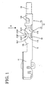
- FIGS. 1 to 3 left sides of FIGS. 1 to 3 are referred to as front; vertical direction is based on FIGS. 1 and 2; transverse direction is based on FIGS. 4 and 5; and right side of FIG. 3 is referred to as upper side.
- An insulation displacement terminal fitting according to this embodiment is produced preferably by stamping out or cutting a flat conductive metal plate 10 preferably having plating applied to its outer surface in a specified shape e.g. by a press, and applying embossing and bending to the stamped-out metal piece.
- a front end portion of the insulation displacement terminal fitting is an engaging portion 11 preferably in the form of a substantially rectangular tube, into which an unillustrated mating terminal fitting is insertable, and a rear end portion thereof is a wire connecting portion 12, which has an insulation displacement portion 13 preferably substantially at its front half and a crimping portion 14 preferably substantially at its rear half (rear end of the insulation displacement terminal fitting).
- the crimping portion 14 is comprised of a pair of crimping pieces 14A standing from a bottom wall 15 and crimped or bent or deformed or deformable into connection with a wire 16.
- the insulation displacement portion 13 is comprised of preferably two pairs of right and left blade portions 17R, 17L (collectively referred to as blade portions 17 in the following description unless either one of the blade portions is specified) which pairs are displaced in forward and backward directions. However, one or three or more blade portions 17 may be provided.
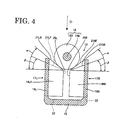
- the respective blade portions 17R, 17L are formed by embossing or bending or deforming side walls 18R, 18L (collectively referred to as side walls 18 in the following description unless either one of the side walls is specified), and are comprised of two blades 19RF, 19RR and two blades 19LF, 19LR (collectively referred to as blades 19 in the following description unless either one of the blades is specified) preferably projecting substantially in V-shape from the side walls 18 when viewed from above (in a direction in which the wire 16 is pushed in between the blade portions 17), and contacting edges 20R, 20L (collectively referred to as contacting edges 20 in the following description unless either one of the contacting edges is specified) vertically (wire pushing or inserting direction D) extending at a projecting end of the blades 19RF, 19RR and a projecting end of the 19LF, 19LR, respectively.
- Each pair of such blade portions 17R, 17L are preferably substantially opposed to each other while providing a specified spacing between the contacting edges 20R, 20L.
- the wire 16 is pushed in between the pair of the blade portions 17R, 17L in a direction arranged at an angle different from 0° or 180°, preferably substantially normal to a longitudinal axis from above.
- the pushed-in wire 16 has its insulation coating 16A, preferably its resin coating 16A cut or notched by cutting or notching edges 21RF, 21RR, 21LF, 21LR (collectively referred to as cutting edges 21 in the following description unless either one of the cutting edges is specified) of the blades 19, and the contacting edges 20R, 20L enter the cuts made in the resin coating 16A to come into contact with a core 16B at the substantially opposite sides.
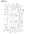
- the blade portions 17 are formed by embossing portions of the flat metal plate piece (see FIG. 6), which become the side walls after bending, by means e.g. of a press.
- the side walls 18 are described here.
- Slits 22 are formed at folds 23F, 23C, 23R extending in the side walls 18 up to the bottom wall 15 in an area where the blade portions 17 are to be formed. The presence of the slits 22 prevents the bottom wall 15 from being distorted when the side walls 18 are embossed.
- a set of three transversely extending folds 23F, 23C, 23R are set at substantially regular intervals in forward and backward directions.
- These two sets of folds 23F, 23C, 23R are preferably symmetrically formed in the left and right side walls 18R, 18L with respect to a center longitudinal axis.
- Two sections between the front and rear folds 23F, 23R and the middle fold 23C become the blades 19 of the blade portions 17, and the middle folds 23C become the contacting edges 20 of the blade portions 17.
- triangular notches 24R, 24L are formed in portions of the plate piece, which become the upper ends of the side walls 18 after bending and where the blade portions 17 are to be formed. Two inclined edges of each of the notches 24R, 24L become the cutting edges 21 of the blades 19.
- the respective notches 24R, 24L are asymmetrical with respect to forward and backward directions as well as transverse direction.
- the front end of the front cutting edge 21 RF is located at the intersection of the side edge of the side wall 18R and the front fold 23F, and the rear end thereof is located at the middle fold 23C.
- the front end of the rear cutting edge 21 RR is located at the middle fold 23C (at the rear end of the front cutting edge 21RF), but the rear end thereof is located further backward from the intersection of the rear fold 23R with the side edge of the side wall 18R. Accordingly, an angle of inclination ⁇ of the front cutting edge 21RF of the right notch 24R with respect to forward and backward directions is larger than an angle of inclination ⁇ of the rear cutting edge 21RR with respect thereto.
- the front cutting edge 21RF having a larger angle of inclination ⁇ comes into contact with the resin coating 16A of the wire before the rear cutting edge 21RR does.
- the front end of the front cutting edge 21LF is located more forward than the intersection of the side edge of the side wall 18L and the front fold 23F, and the rear end thereof is located at the middle fold 23C.
- the front end of the rear cutting edge 21LR is located at the middle fold 23C (at the rear end of the front cutting edge 21LF), and the rear end thereof is located at the intersection of the rear fold 23R with the side edge of the side wall 18L. Accordingly, an angle of inclination of the front cutting edge 21 LF with respect to forward and backward directions is smaller than an angle of inclination a of the rear cutting edge 21LR with respect thereto.
- the rear cutting edge 21LF having a larger angle of inclination ⁇ comes into contact with the resin coating 16A of the wire before the rear cutting edge 21 RR does.
- the right and left notches 24R, 24L are preferably symmetrical with respect to an intersection P (FIG. 6) of a widthwise center line of the bottom wall 15 and a line connecting the two middle folds 23.
- the angles of inclination of the front cutting edge 21RF at the right side and of the rear cutting edge 21 LR at the left side are substantially the same, i.e. ⁇
- the angles of inclination of the rear cutting edge 21 RR at the right side and of the front cutting edge 21LF at the left side are substantially the same, i.e. ⁇ .
- Jigs are or can be placed along the respective folds 23F, 23C, 23R of the side walls 18R, 18L in the development of the metal plate piece, and the blade portions 17R, 17L are formed by embossing e.g. by means of a press. Thereafter, the side walls 18R, 18L are bent at an angle different from 0° or 180°, preferably at a substantially right angle to the bottom wall 15 to form the insulation displacement portion 13.
- the cutting edges 21RF, 21LR having the larger angle of inclination ⁇ and the cutting edges 21RR, 21 LF having the smaller angle of inclination ⁇ are located substantially on diagonal lines, respectively, as shown in FIG. 3. It should be noted that embossing is applied such that the angles of inclinations ⁇ , ⁇ of the respective cutting edges 21 with respect to a horizontal line when viewed from front are the same as those in the development of the plate piece.
- the wire 16 When being pushed into the insulation displacement portion 13, the wire 16 first comes into contact with the cutting edges 21RF, 21LR having the larger angle of inclination ⁇ as shown in FIG. 4. These two cutting edges 21RF, 21LR preferably are substantially parallel to each other when viewed from above (when viewed in the pushing direction of the wire 16) as shown in FIG. 3 as if they would form portions of one blade.
- the resin coating 16A is first cut by the cutting edges 21RF, 21LR having the larger angle of inclination ⁇ and then cut by the cutting edges 21RR, 21LF having the smaller angle of inclination ⁇ .
- the contacting edges 20R, 20L forcibly enter the cut portions of the resin coating 16A to contact the core 16B at the opposite sides.
- the two blades 19 having a V-shape do not simultaneously cut it, but one of them first coming into contact with the resin coating 16A cuts it substantially as a single blade would do. Accordingly, a resistance (insulation displacement resistance) during cutting can be reduced.
- the position of the wire 16 can be corrected (to a widthwise center position) even if the wire 16 is displaced with respect to widthwise direction, avoiding an erroneous cutting operation and a contact failure between the blade portions 17 and the core 16B.
- the wire 16 is pressed in oblique directions by the respective cutting edges due to an elastic restoring force of the resin coating 16A while the resin coating 16A is being cut, and pushed along the longitudinal direction (e.g.
Landscapes
- Connections By Means Of Piercing Elements, Nuts, Or Screws (AREA)
- Manufacturing Of Electrical Connectors (AREA)
Claims (9)
- Raccord de borne à déplacement d'isolant comprenant au moins une paire de portions de lame (17) de sorte qu'un câble (16) peut être poussé entre les portions de la dite au moins une paire de portions de lame (17) dans une direction suivant un angle différent de 0 degré ou 180 degrés, et de préférence sensiblement de 90 degrés, par rapport à son axe longitudinal ;
chaque portion de lame (17) comprenant deux lames (19) et des bords de contact (20) étant formés dans une direction de poussée de câble (D) à partir de l'etrémité en saillie des deux lames (19) ;
des bords coupants (20) étant prévus sur les lames (19) de sorte qu'un revêtement isolant (16A) du câble (16), poussé entre les deux portions de lame (17), peut être coupé par les bords coupants (21) des lames (19) afin de mettre en contact une âme (16B) du câble (16) avec les bords de contact (20),
caractérisé en ce que les instants de contact des bords coupants (21) des deux lames (19) avec le revêtement isolant (16A) sont différents du fait d'angles d'inclinaison différents (α, β) des bords coupants (21) et/ou du fait que les bords coupants (21) dès deux lames (19) formant de préférence sensiblement un V sont agencés sur les deux portions de lame (17) de la dite au moins une paire de portions de lame (17) de façon à venir en contact avec le revêtement isolant (16A) à des instants différents pendant que le câble (16) est poussé dans le raccord. - Raccord de borne à déplacement d'isolement selon la revendication 1, dans lequel les lames (19) sont formées par pliage de portions des parois latérales (18) du raccord de borne à déplacement d'isolant, vers l'intérieur.
- Raccord de borne à déplacement d'isolant selon une ou plusieurs des revendications précédentes, dans lequel les lames (19) font saillie sensiblement en forme de V lorsqu'elles sont vues dans une direction de poussée de câble (D) dans laquelle le câble doit être poussé.
- Raccord de borne à déplacement d'isolant selon une ou plusieurs des revendications précédentes, dans lequel les bords de contact (20) s'étendent de façon continue dans la direction de poussée du câble, à partir de l'extrémité en saillie des deux lames (19).
- Raccord de borne à déplacement d'isolant selon une ou plusieurs des revendications précédentes, dans lequel les bords coupants (21) des deux lames (19) formant de préférence sensiblement un V sont inclinés à partir d'une paroi latérale correspondante (18) du raccord de borne à déplacement d'isolant, vers le bord de contact correspondant (20), dans des directions telles que le câble (16) est guidé latéralement.
- Raccord de borne à déplacement d'isolant selon une ou plusieurs des revendications précédentes, dans lequel les instants de contact des bords coupants (21) des deux lames (19) avec le revêtement isolant (16A) sont décalés du fait des positions différentes auquelles les lames (19) sont placées le long de la direction de poussée (D) du câble.
- Raccord de borne à déplacement d'isolant selon une ou plusieurs des revendications précédentes, dans lequel les bords coupants (21) de la paire de portions de lame (17) sensiblement mutuellement opposés lorsqu'ils sont vus dans la direction de poussée (D) du câble viennent en contact avec le revêtement isolant (16A) sensiblement en même temps.
- Raccord de borne à déplacement d'isolant selon une ou plusieurs des revendications précédentes, dans lequel les bords coupants (21) de la dite une paire de portions de lame (17) sensiblement mutuellement opposés sont sensiblement mutuellement parallèles.
- Procédé de fabrication d'un raccord de borne à déplacement d'isolant selon une ou plusieurs des revendications précédentes, ayant des portions de lame (17) qui comportent des lames (19) ayant des bords coupants (21) pour couper un revêtement isolant (16A) d'un câble (16), comprenant les étapes suivantes :dans lequel des encoches sensiblement triangulaires (24R, 24L) sont formées dans des parties de la pièce plate qui correspondent aux extrémités supérieures des parois latérales (18) après pliage et à l'endroit où les portions de lame (17) doivent être formées, de sorte que deux bords inclinés de chacune des encoches sensiblement triangulaires (24R, 24L) correspondent aux bords coupants (21) des lames (19).formation de parois latérales (18) par pliage d'une pièce métallique plate ;formation de fentes (22) à l'endroit de plis (23F ; 23C ; 23R) s'étendant dans les parois latérales (18) de préférence jusqu'à une paroi inférieure (15) dans une région où les portions de lame (17) doivent être formées;création d'un groupe de trois plis transversaux (23F, 23C, 23R) dans une région où chaque fente (22) est formée, de préférence à intervalles réguliers dans des directions avant et arrière, de sorte que deux sections entre les premier et troisième plis, ou plis avant et arrière, (23F, 23R) et le deuxième pli ou pli central (23C) correspondent aux lames (19) des portions de lame (17), et les deuxièmes plis ou plis centraux (23C) correspondent aux bords de contact (20) des portions de lame (17) ;repoussage de portions des parois latérales (18) pour former les portions de lame (17) ; et
Applications Claiming Priority (2)
| Application Number | Priority Date | Filing Date | Title |
|---|---|---|---|
| JP35973299 | 1999-12-17 | ||
| JP35973299A JP3528730B2 (ja) | 1999-12-17 | 1999-12-17 | 圧接端子金具 |
Publications (2)
| Publication Number | Publication Date |
|---|---|
| EP1109255A1 EP1109255A1 (fr) | 2001-06-20 |
| EP1109255B1 true EP1109255B1 (fr) | 2003-09-24 |
Family
ID=18466028
Family Applications (1)
| Application Number | Title | Priority Date | Filing Date |
|---|---|---|---|
| EP00127220A Expired - Fee Related EP1109255B1 (fr) | 1999-12-17 | 2000-12-14 | Contact à déplacement d'isolant et méthode de fabrication |
Country Status (4)
| Country | Link |
|---|---|
| US (1) | US6354863B2 (fr) |
| EP (1) | EP1109255B1 (fr) |
| JP (1) | JP3528730B2 (fr) |
| DE (1) | DE60005467T2 (fr) |
Family Cites Families (11)
| Publication number | Priority date | Publication date | Assignee | Title |
|---|---|---|---|---|
| US3902154A (en) * | 1974-02-19 | 1975-08-26 | Trw Inc | Strain relief |
| US4040702A (en) * | 1975-06-23 | 1977-08-09 | Trw Inc. | Solderless termination system |
| US4427251A (en) * | 1977-04-18 | 1984-01-24 | Allied Corporation | Electrical connector having displaceable sidewall terminal element |
| US4385794A (en) * | 1978-07-25 | 1983-05-31 | Amp Incorporated | Insulation displacement terminal |
| US4660917A (en) * | 1985-12-23 | 1987-04-28 | Molex Incorporated | Multi-wire insulation displacement terminal |
| US4840578A (en) * | 1986-10-30 | 1989-06-20 | Hirose Electric Co., Ltd. | Electrical contact |
| GB8817783D0 (en) * | 1988-07-26 | 1988-09-01 | Amp Gmbh | Electrical contact member |
| US5133672A (en) * | 1991-08-09 | 1992-07-28 | Molex Incorporated | Insulation displacement terminal |
| US5125851A (en) * | 1991-09-23 | 1992-06-30 | Molex Incorporated | Insulation displacement terminal for an electrical connector |
| GB9500782D0 (en) * | 1995-01-16 | 1995-03-08 | Amp Gmbh | Insulation displacement contact for multiple wire sizes |
| JP3225861B2 (ja) * | 1996-12-02 | 2001-11-05 | 住友電装株式会社 | 端子金具 |
-
1999
- 1999-12-17 JP JP35973299A patent/JP3528730B2/ja not_active Expired - Fee Related
-
2000
- 2000-12-14 EP EP00127220A patent/EP1109255B1/fr not_active Expired - Fee Related
- 2000-12-14 DE DE60005467T patent/DE60005467T2/de not_active Expired - Fee Related
- 2000-12-18 US US09/740,327 patent/US6354863B2/en not_active Expired - Fee Related
Also Published As
| Publication number | Publication date |
|---|---|
| EP1109255A1 (fr) | 2001-06-20 |
| JP3528730B2 (ja) | 2004-05-24 |
| DE60005467D1 (de) | 2003-10-30 |
| DE60005467T2 (de) | 2004-07-01 |
| US20010012720A1 (en) | 2001-08-09 |
| US6354863B2 (en) | 2002-03-12 |
| JP2001176568A (ja) | 2001-06-29 |
Similar Documents
| Publication | Publication Date | Title |
|---|---|---|
| US4261629A (en) | Slotted plate terminal | |
| US4712299A (en) | Process for producing electrical contacts for facilitating mass mounting to a contact holder | |
| US4735575A (en) | Electrical terminal for printed circuit board and methods of making and using same | |
| EP0767514B1 (fr) | Contact électrique socle couvert en une pièce et méthode de fabrication | |
| EP0944130A2 (fr) | Connection par sertissage | |
| US4035049A (en) | Universal solderless termination system | |
| EP0844688A2 (fr) | Contact à pression avec organe de contact | |
| EP0372767B1 (fr) | Contact électrique miniature à déplacement d'isolation | |
| JP3463900B2 (ja) | 電気コネクタ及びその製造方法 | |
| US5711690A (en) | Electrical contact and method for making same | |
| US4780958A (en) | Method of making an electrical terminal for a printed circuit board | |
| CA1150378A (fr) | Plaque de branchement ajouree transformable en plaque a broches | |
| EP0876693A2 (fr) | Bloc de connexion pour cables de type 110 | |
| JPH11505664A (ja) | 電線接続システム | |
| US6422878B1 (en) | Plug-type connector and method of manufacturing a plug-type connector | |
| EP1109255B1 (fr) | Contact à déplacement d'isolant et méthode de fabrication | |
| EP1058342B1 (fr) | Organe de contact et procédé de fabrication | |
| US6450831B2 (en) | Terminal fitting with crimping pieces and portions for restricting wire movement | |
| US6132237A (en) | IDC contact with arcuate terminating means for thin wire | |
| EP1128469B1 (fr) | Contact à déplacement d'isolant et son procédé de fabrication | |
| EP1109254B1 (fr) | Contact autodénudant et son procédé de fabrication | |
| EP0125098A1 (fr) | Une méthode pour former des fiches électriquement conductrices | |
| US6413115B2 (en) | Insulation-displacement terminal fitting | |
| US6296512B1 (en) | Press-connecting terminal | |
| EP0214176B1 (fr) | Terminal electrique avec fente de reception de fil pour fils de diametre relativement petit et connecteurs contenant ces terminaux |
Legal Events
| Date | Code | Title | Description |
|---|---|---|---|
| PUAI | Public reference made under article 153(3) epc to a published international application that has entered the european phase |
Free format text: ORIGINAL CODE: 0009012 |
|
| 17P | Request for examination filed |
Effective date: 20010111 |
|
| AK | Designated contracting states |
Kind code of ref document: A1 Designated state(s): DE FR GB IT |
|
| AX | Request for extension of the european patent |
Free format text: AL;LT;LV;MK;RO;SI |
|
| 17Q | First examination report despatched |
Effective date: 20020129 |
|
| AKX | Designation fees paid |
Free format text: DE FR GB IT |
|
| GRAH | Despatch of communication of intention to grant a patent |
Free format text: ORIGINAL CODE: EPIDOS IGRA |
|
| GRAH | Despatch of communication of intention to grant a patent |
Free format text: ORIGINAL CODE: EPIDOS IGRA |
|
| GRAA | (expected) grant |
Free format text: ORIGINAL CODE: 0009210 |
|
| AK | Designated contracting states |
Kind code of ref document: B1 Designated state(s): DE FR GB IT |
|
| PG25 | Lapsed in a contracting state [announced via postgrant information from national office to epo] |
Ref country code: IT Free format text: LAPSE BECAUSE OF FAILURE TO SUBMIT A TRANSLATION OF THE DESCRIPTION OR TO PAY THE FEE WITHIN THE PRESCRIBED TIME-LIMIT;WARNING: LAPSES OF ITALIAN PATENTS WITH EFFECTIVE DATE BEFORE 2007 MAY HAVE OCCURRED AT ANY TIME BEFORE 2007. THE CORRECT EFFECTIVE DATE MAY BE DIFFERENT FROM THE ONE RECORDED. Effective date: 20030924 |
|
| REG | Reference to a national code |
Ref country code: GB Ref legal event code: FG4D |
|
| REF | Corresponds to: |
Ref document number: 60005467 Country of ref document: DE Date of ref document: 20031030 Kind code of ref document: P |
|
| PGFP | Annual fee paid to national office [announced via postgrant information from national office to epo] |
Ref country code: FR Payment date: 20031215 Year of fee payment: 4 |
|
| PGFP | Annual fee paid to national office [announced via postgrant information from national office to epo] |
Ref country code: DE Payment date: 20040225 Year of fee payment: 4 |
|
| ET | Fr: translation filed | ||
| PLBE | No opposition filed within time limit |
Free format text: ORIGINAL CODE: 0009261 |
|
| STAA | Information on the status of an ep patent application or granted ep patent |
Free format text: STATUS: NO OPPOSITION FILED WITHIN TIME LIMIT |
|
| 26N | No opposition filed |
Effective date: 20040625 |
|
| PG25 | Lapsed in a contracting state [announced via postgrant information from national office to epo] |
Ref country code: GB Free format text: LAPSE BECAUSE OF NON-PAYMENT OF DUE FEES Effective date: 20041214 |
|
| PG25 | Lapsed in a contracting state [announced via postgrant information from national office to epo] |
Ref country code: DE Free format text: LAPSE BECAUSE OF NON-PAYMENT OF DUE FEES Effective date: 20050701 |
|
| GBPC | Gb: european patent ceased through non-payment of renewal fee |
Effective date: 20041214 |
|
| PG25 | Lapsed in a contracting state [announced via postgrant information from national office to epo] |
Ref country code: FR Free format text: LAPSE BECAUSE OF NON-PAYMENT OF DUE FEES Effective date: 20050831 |
|
| REG | Reference to a national code |
Ref country code: FR Ref legal event code: ST |