EP1126172B1 - Pompe péristaltique pour une imprimante à jet d'encre - Google Patents
Pompe péristaltique pour une imprimante à jet d'encre Download PDFInfo
- Publication number
- EP1126172B1 EP1126172B1 EP01103515A EP01103515A EP1126172B1 EP 1126172 B1 EP1126172 B1 EP 1126172B1 EP 01103515 A EP01103515 A EP 01103515A EP 01103515 A EP01103515 A EP 01103515A EP 1126172 B1 EP1126172 B1 EP 1126172B1
- Authority
- EP
- European Patent Office
- Prior art keywords
- tube
- pump
- ink
- drive shaft
- set forth
- Prior art date
- Legal status (The legal status is an assumption and is not a legal conclusion. Google has not performed a legal analysis and makes no representation as to the accuracy of the status listed.)
- Expired - Lifetime
Links
Images


Classifications
-
- F—MECHANICAL ENGINEERING; LIGHTING; HEATING; WEAPONS; BLASTING
- F04—POSITIVE - DISPLACEMENT MACHINES FOR LIQUIDS; PUMPS FOR LIQUIDS OR ELASTIC FLUIDS
- F04B—POSITIVE-DISPLACEMENT MACHINES FOR LIQUIDS; PUMPS
- F04B43/00—Machines, pumps, or pumping installations having flexible working members
- F04B43/12—Machines, pumps, or pumping installations having flexible working members having peristaltic action
- F04B43/1207—Machines, pumps, or pumping installations having flexible working members having peristaltic action the actuating element being a swash plate
Definitions
- the present invention generally relates to a tube pump for generating a pressure by pressing and deforming a tube. More particularly, the invention relates to an ink jet recording apparatus using the tube pump, which is capable of restoring an ink ejection capability of the print head by discharging ink from the print head by utilizing a negative pressure generated by the tube pump. Further, the invention relates to an ink jet recording apparatus which is provided with the tube pump as an ink supplier for supplying ink from a main tank (ink pack) to a sub-tank.
- the ink jet recording apparatus is advantageous in that noise generated during the printing operation is low, and small print dots may be arrayed at high density. Because of those advantages, the ink jet recording apparatus has used for a variety of printings, mainly for color printing, recently.
- the ink jet recording apparatus is provided with an ink jet recording head which receives ink from an ink cartridge, and a paper feeder for moving a recording sheet relatively to the recording head. To print, the ink jet recording apparatus, while moving the recording head, causes the recording head to eject ink drops onto the recording sheet and forms ink dots thereon, in accordance with a print signal.
- the ink jet recording apparatus must unavoidably handle with liquid ink. Accordingly, to prevent the clogging of the nozzle orifices, which is caused by filling of ink to the recording head and volatilization of ink solvent, a process to restore the ink-ejection capability of the recording head is carried out in which ink is forcibly sucked and discharged from the recording head.
- the forcible discharging of ink which is performed for removing the nozzle clogging or when air bubbles are left in the recording head, is called a cleaning operation.
- the cleaning operation is carried out when the recording apparatus, which is not in use for a long time, is operated again, and when the user finds out poor print, such as blur of printed characters, and operates a cleaning switch.
- the recording head is sealingly capped with a capping member, and a negative pressure is applied to the capped head to forcibly discharge ink, by sucking, into the capping member through the nozzle orifices of the recording head.
- the ink discharged into the capping member is sucked and sent to a used ink tank by the utilization of a negative pressure.
- the nozzle plate of the recording head is wiped out by a cleaning member formed with an elastic material, e.g., rubber.
- a called tube pump has been used for the means for applying a negative pressure into the capping member since it is relatively simple in structure and easy to be reduced in size, and further does not soil the mechanism for sucking and discharging ink.
- the tube pump will be described in detail with reference to Fig. 31.
- the tube pump 74 includes a pump frame 72. a pump wheel 70, and a pair of rollers 71a and 71b.
- the pump frame 72 has a tube support surface 76 arcuately defining a configuration of a flexible tube 75.
- the pump wheel 70 is rotated by a motive power transmitted from a drive member such as a sheet-feeding motor.
- a couple of roller support grooves 70a and 70b are disposed while being radially slanted between an axial direction and a circumferential direction of the pump wheel 70.
- the rollers 71a and 71b are rotatably mounted so that those are movable within and along the roller support grooves 70a and 70b, respectively.
- a pair of guide members 73a and 73b are disposed at positions facing the pump wheel 70 formed on the pump frame 72, while extending in the axial direction of the pump wheel 70.
- L-shaped engaging grooves 72a and 72b are formed in the pump frame 72.
- the guide members 73a and 73b are planted in those engaging grooves 72a and 72b, respectively.
- the guide members 73a and 73b guide respectively the rollers along the roller support grooves in the rotation backward direction, with rotation of the pump wheel.
- the rollers 71 a and 71 b are pushed back by the guide members 73a and 73b made of the elastic material, respectively.
- the rollers 71a and 71b respectively, move in the outer circumference direction of the roller support grooves 70a and 70b, and the flexible tube 75 is compressed flat. Accordingly, a reliability of the pump driving operation is improved.
- the tube pump is used for restoring the ink-ejection capability to cause the recording head to discharge ink therefrom, and also for supplying ink from a main tank, which stores ink therein, to a sub-tank provided in the recording head.
- the ink jet recording apparatus which is used for office or business use, needs an ink cartridge of a large capacity since it handles a relatively large amount of printing. For this reason, a main tank as an ink cartridge (ink pack) is set to a cartridge holder, which is located on the side of the body of the recording apparatus.
- the sub-tank is placed on the carriage on which the recording head is mounted. Ink is supplied from the main tank to the sub-tank via an ink supplying tube. Further, ink is supplied from the sub-tank to the recording head.
- the tube pump is used as the ink supplier for supplying ink from the main tank to the sub-tank.
- the roller rotates while successively pressing the tube flat. Through the operation, a pressure is generated within the tube to give rise to a negative pressure.
- the tube being pressed flat by the rotating roller is restored to its original shape by an elasticity of the flexible tube per se (self-restoring ability).
- the thickness (difference between the inner and outer diameters of the tube) of the flexible tube must be secured in a certain level. If the flexible tube is extremely thin, the restoring force is unsatisfactory, and a required suction force cannot be produced.
- the inner diameter of the tube is small, so that a predetermined quantity of suction cannot be secured. If the inner diameter of the flexible tube is set at a fixed value, the outer diameter is also large, and consequently the whole tube pump is large in size, and hence the ink jet recording apparatus itself is large in size.
- the tube pressed flat restores to its initial state by the elasticity (self-restoring ability) of the tube itself.
- the material which may be used for the tube must be selected from among limited kinds of materials.
- the metal tube made of aluminum or the like has less elasticity, and hence cannot be used for the tube of the related tube pump.
- the elasticity (self-restoring ability) of the tube per se serves as a reaction force when the tube is pressed flat. This results in increase of the pressing load, so that the pump efficiency is impaired.
- EP-A-0 056 019 discloses a spring flattening the tube between a base and a rocking disk in that the rocking disk is urged toward the base.
- the present invention has an object to provide a tube pump which is different in basic construction from the related tube pump, allows the use of a tube not having the self-restoring ability and is small in size and high in pump efficiency wherein the tube is pressed flat by a fixed pressing force.
- the invention has another object to provide an ink jet recording apparatus constructed using such a tube pump.
- a tube pump comprising:
- the tube is gradually pressed flat through a swing motion of the tube pressing member, and is returned to its original state. Accordingly, a tube having a small self-restoring ability or a low stiffness may be used for the tube. A thin tube may also be used. As a result, the size reduction of the tube pump is realized.
- fix means a case where the tube is fastened to the tube pressing member, the tube fixing plate or the like by means of adhesion, and further welding, and further a case where the tube pressing plate or the like is formed integral with at least a part of the tube.
- the tube pump further comprises a spring member, for urging the fixing member toward the tube pressing member.
- the tube pressing member of the present invention is provided as a plate member which is opposed to the rotor.
- the rotor of the present invention is provided as a rotary disk member.
- the swinging member includes: a spring member, one end of which is fixed to the rotary disk member; a ball body, being movable on an upper face of the tube pressing plate; and a holder, to which the other end of the spring member is fixed, the holder for holding the ball body.
- the ball body is pressed against the tube pressing plate with the aid of the spring member. Accordingly, the tube pressing plate is swung at a fixed pressing force.
- a through hole is formed at a center portion of the tube pressing plate, through which the drive shaft is inserted.
- the diameter of the through hole is larger than the diameter of the drive shaft.
- a cylindrical member is formed on a lower face of the tube pressing plate so as to surround the through hole.
- the tube pressing plate stably swings.
- the drive shaft sometimes comes in contact with the inner wall of the through hole of the tube pressing plate.
- the contact of the drive shaft with the tube pressing plate reduces the pump efficiency. Such a situation should be avoided as possible.
- the tube is fixed to the tube pressing member and the fixing member by either adhesive or welding.
- the pressing/expanding operation can be stably performed, after the assembling.
- the tube pressing member, the tube and the fixing member are integrally formed.
- the assembling work may be omitted.
- the tube pressing member is provided with a hole for holding a projection formed on the upper outer face of the tube.
- the fixing member is provided with a hole for holding a projection formed on the lower outer face of the tube.
- the tube and the fixing member are integrally formed.
- a hook member is formed on the upper outer face of the tube, which is engaged with an engagement member formed on the lower portion of the tube pressing member.
- the tube includes an upper tube part and a lower tube part, which are connected to form a tube.
- An upper face of the upper tube part and the tube pressing member are integrally formed.
- a lower face of the lower tube part and the fixing member is integrally formed.
- the tube may be made of a material having a relatively low self-restoring ability, or a material having a relatively low stiffness.
- An aluminum tube, an aluminum tube coated with resin or laminated with a resin layer, or a vinyl tube may be used for the tube.
- the tube pressing member always presses at least a part of the tube.
- an ink jet recording apparatus may use the thus constructed tube pump as a pump unit for sucking ink from the recording head.
- the size of apparatus is reduced and the suction operation is stably and highly efficiently performed.
- an ink.jet recording apparatus may use the thus constructed tube pump as an inky supplier for supplying ink from the main tank to the sub-tank.
- the size of apparatus is reduced and the ink supplying operation is stably and highly efficiently performed.
- FIG. 1 is a perspective view showing an overall construction of an ink jet recording apparatus incorporating the present invention thereinto.
- reference numeral 1 denotes a carriage.
- the carriage 1 while being guided, is reciprocately moved in the axial directions of a platen 5 with the aid of a timing Belt 3 driven by a carriage motor.
- An ink jet recording head 7 is mounted on the side of the carriage 1, which is confronted with a recording sheet 6.
- a black ink cartridge 8 and a color ink cartridge 9, which are for supplying ink to the recording head are detachably attached to the upper side of the head.
- reference numeral 10 denotes a capping unit located at a non-recording region (home position).
- the capping unit Lifts and sealingly caps the no77le face of the recording head with itself.
- a tube pump 11 as a pump unit for supplying a negative pressure to an inside space of the capping unit 10 is located under the capping unit 10. The tube pump 11 will be described in detail later.
- the capping unit 10 serves as a cover member for preventing the no77le orifices of the recording head from being dried during a rest period of the ink jet recording apparatus.
- the tube pump also serves as an ink receptacle when the recording head is put in a flushing mode in which a drive Signal having no connection with the recording operation is applied to the recording head to cause the recording head to eject ink in an idling manner. Further, it serves as a cleaning means which applies a negative pressure, which is derived from the tube pump 11, to the recording head, and absorbs ink.
- a wiper 12 is horizontally movably provided near the side of the capping unit 10 which is closer to a recording region.
- the wiper is provided with an elastic plate made of rubber or the like. The wiper may advance to a traveling moving path of the recording head when the carriage 1 moves to and from the capphg unit 10.
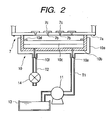
- FIG. 2 schematically illustrates a structure of the ink jet recording apparatus shown in Fig. 1, which includes the capping unit 10, the tube pump 11 connected to the capping unit and others.
- the capping unit 10 includes a rectangular cap case 10a opened at the top, and a cap member 10b which is made of a flexible material, such as rubber, and contained in the cap case 10a.
- the cap member 10b somewhat protrudes above and its top is somewhat higher than the cap case 10a.
- An ink absorbing member 10c made of porous material is placed an the bottom in the cap member 10b, and held with a holder member 10d, which is formed integrally with the cap member 10b.
- a suction port 10e and an air release port 10f are formed in the bottom of the cap case 10a while passing through the cap case 10a and the cap member 10b.
- the tube pump 11 is connected to the suction port 10e of the cap case 10a via a tube T1.
- a discharge end of the tube pump 11 is connected to the ink absorbing material contained in a used ink tank 13, as will be described later.
- An air release valve 14 is connected to an air release port 10f of the cap case 10a via another tube T2.
- reference numeral 7 denotes a recording head.
- the recording head 7 is arranged such that it moves with movement of the carriage, and when it reaches a position above the capping unit 10, the nozzle face 7a of it is capped with the cap member 10b.
- a number of nozzle orifices 7b are formed in the nozzle face 7a of the recording head.
- Piezoelectric vibration elements 7c are respectively disposed in association with nozzle orifices 7b. When those piezoelectric vibration elements are selectively driven, color inks of black, yellow, cyan and magenta are selectively ejected from the nozzle orifices.
- the operation to discharge air bubbles left in the recording head or the ink supplying passage and the ink sucking operation to remove the clogging of the nozzle orifice or orifices are performed in a state that, as shown in Fig. 2, the cap member 10b is brought into close contact with the nozzle face 7a of the print head 7, and the air release valve 14 is closed.
- the tube pump 11 is driven, a negative pressure is applied to the inside space of the cap member 10b, and ink is sucked and discharged through the nozzle orifices 7b of the print head 7.
- the drive of the pump is continued for a predetermined time period, and then stopped.
- the air release valve 14 is opened.
- air is introduced into the cap member, and the negative Pressure disappears.
- the tube pump 11 is driven again in a state that the air release valve 14 is left open. And the ink discharged into the cap member is fed through a tube T1 to a used ink tank 13.
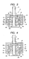
- the tube pump 11 is made up of a drive shaft 21, a rotary disc 22, a tube pressing plate 23, a metal ball 24, and a tube 25.
- the rotary disc 22 as an elastic rotary body is fastened to the drive shaft 21.
- the tube pressing plate 23 serving as a tube pressing member is swingable facing the rotary disc 22.
- the metal ball 24 serving as a swinging member is interposed between the rotary disc 22 and the tube pressing plate 23, and presses downward the tube pressing plate 23.
- the upper side of the tube 25 is fixed to the tube pressing plate 23, while the lower side thereof is fixed to the case.
- the drive shaft 21 is provided with a flange 21 a.
- the rotary disc 22 is fastened to the flange 21 a by fastening members 28, such as screws. it is rotated with rotation of the drive shaft 21.
- the rotary disc 22 is made of an elastic material, such as metal, and generates a force to press downward the tube pressing plate 23 through the metal ball 24.
- a groove 23a is formed in the upper surface of the tube pressing plate 23.
- the metal ball 24 is rollable within the groove.
- a through hole 23b through which the drive shaft 21 passes is formed in a central part of the tube pressing plate 23.
- a tapered portion 23c whose diameter gradually reduces is formed at the top end portion of the through hole 23b.
- a hole 23d being fixed in diameter is formed continuous to the tapered portion 23c.
- a peripheral wall 23e whose top part is arcuate is formed around the rear end of the through hole 23b. The peripheral wall 23e comes in contact with the case 26.
- Through holes 23f are formed in the lower side of the tube pressing plate 23. Those are used for fixing engaging protrusions 25a protruded from the top wall of the tube 25.
- the through hole 23f is continuously formed along the tube 25.
- Through holes 26a are formed in the case 26, and are used for fixing engaging protrusions 25b protruded from the lower wall of the tube 25.
- the tube 25, unlike the related one, may be made of a material, which does not have a self-restoring ability or a low stiffness, viz., a material having an elasticity.
- An aluminum tube, an aluminum tube coated with resin or laminated with a resin layer, or a vinyl tube may be used for the tube 25.
- the tube 25 may be thin.
- the tube pressing plate 23 slants (swings) from the upper position to the lower position to press the tube 25 flat for its closing.
- the tube pressing plate 23 moves from the upper position to the lower position as the metal ball 24 becomes more distant. With the movement of the tube pressing plate, the tube 25 gradually resumes its initial shape from the pressed state.
- the tube 25 resumes its initial shape through the action of the tube pressing plate 23. Therefore, as described above, the tube 25 is able to perform a desired sucking operation, even if it is made of a material not having a self-restoring ability or is thin in thickness.
- the metal ball 24 successively moves (swings) the tube pressing plate 23, so that a negative pressure is applied to the inside space of the cap member 10b, and ink is sucked and discharged through the nozzle orifices 7b of the print head 7.
- the drive shaft 21 After the tube pump 11 is driven for a fixed time, the drive shaft 21 is stopped in rotation. Thereafter, at a time point where the negative pressure reduces by a certain value of pressure, the air release valve 14 is opened. Then, air is introduced into the cap member and the negative pressure disappears. Subsequently, the drive shaft 21 is rotated again while the air release valve 14 is left open. And ink discharged into the cap member is fed to the used ink tank 13.
- Fig. 6 shows a tube pump according to a second example.
- a fitting hole 22a which receives a part of the metal ball 24, is bored in the rotary disc 22.
- a rotation of the drive shaft 21 is completely transmitted to the metal ball 24.
- the metal ball 24 slants the tube pressing plate 23 as a tube pressing member.
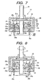
- Figs. 7 and 8 show a tube pump according to a third example.
- a groove which receives the swinging member in a fitting fashion, is formed in the upper surface of the tube pressing plate.
- the center of the groove is formed at a position which is closer to the drive shaft than the center of the cross section of the tube.
- the groove 23a having a V-shaped cross section is formed at a position which is closer to the drive shaft 21 than a center 25c of the cross section of the tube 25.
- a pressing force of the tube pressing plate 23 to press the tube 25 is uniformly exerted an the tube 25 during the tube pressing. Accordingly, the quantity of the tube pressing for closing the tube 25 and a pressing load may be reduced. Further, the closing state of the tube may be kept stably at all times. Therefore, the driving (slanting) operation of the tube pressing plate is stable. Consequently, the size reduction and high efficiency of the ink jet recording apparatus are secured.
- Fig. 9 shows a tube pump according to a fourth example.
- the pressing force of the metal ball 24 against the tube pressing plate 23, which is generated by an elasticity of the rotary disc 22, is generated by a tube fixing plate 31.
- a spring 30 is interposed between the tube fixing plate 31 and the case 26.
- the tube fixing plate 31 presses the tube 25 toward the tube pressing plate 23 with the aid of the spring.
- Fig. 10 shows a tube pump according to a fifth example.
- a spring 32 is placed between the tube fixing plate 31 and the drive shaft 21.
- a flange 21 b is formed around the bottom end of the drive shaft 21.
- a spring 32 is placed between the flange 21 b and a spring engaging plate 33.
- a ball bearing 34 is provided between the spring engaging plate 33 and the tube fixing plate 31.
- the spring engaging plate 33 and the tube fixing plate 31 press upward the tube fixing plate 31, and in turn the tube fixing plate 31 presses the tube 25 toward the tube pressing plate 23.
- the spring engaging plate 33 also rotates together with the shaft.
- the metal ball is used as the swinging member
- the metal ball may be replaced with a protrusion protruded from the rotary disc toward the tube pressing plate.
- a cylindrical member such as a roller, may be used instead of the metal ball.
- the material of the swinging member is not limited to metal, but may be resin.
- the drive shaft and the rotary disc are separately provided: Instead, a unitary member may be used.
- Fig. 11 shows a pump tube according to a sixth example.
- the tube pump is made up of a drive shaft 21, a tube pressing plate 35 which is slidable with rotation of the drive shaft 21, and a tube 25 whose upper wall is fixed to the lower side of the tube pressing plate 35, and lower wall is fixed to the case.
- the drive shaft and the tube pressing plate 35 are coupled with each other through a ball bearing 36.
- the drive shaft 21 includes a tapered portion 21 c, which corresponds to a rotary body rotating together with the drive shaft.
- a ball bearing 36 is mounted on the tapered portion 21 c.
- the tube pressing plate 35 To press the tube by a fixed pressing force, it is preferable to form the tube pressing plate 35 by using an elastic material, e.g., a metal.
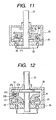
- Figs. 12, 13A and 13B show a pump tube according to an embodiment of the invention.
- the rotary disc 22 and the metal ball 24 are altered.
- a recess 37a is formed in the lower side of a rotary disc 37, as a rotary body, which is fastened to the drive shaft 21 and rotated together with it.
- a spring 37b is fixed at one end to the bottom of the recess 37a. The other end of the spring 37b is fixed to the upper side of a holder member 37c.
- a ball 37d is held on the lower side of the holder member 37c. The ball, while pressing, slides on the tube pressing plate 23.
- One or two balls 37d are arranged in the sliding direction.
- the ball 37d acts an the tube pressing plate 23 by a fixed pressing force. Accordingly, the tube 25 is pressed to be flat, by a fixed pressing force.
- Fig. 14 shows a tube pump according to another example.
- the rotary disc 22, the metal ball 24 and the tube pressing plate 23 are altered.
- the tube pump is provided with a rotary conical body 38 which is fastened to the drive shaft 21 and rotates together with the latter.
- a recess 38a is formed in a slanted surface of the rotary conical body 38.
- a frustum body 39 is held which slides an a tube pressing plate 40 while pressing the latter.
- the tube pressing plate 40 is conical in shape.
- the drive shaft 21 is mounted passing through the vertex of the conical tube pressing plate 40, and the tube pressing plate is swingable with the vertex as its swing center. Specifically, the drive shaft 21 loosely passes through a through hole 40a so as to allow the tube pressing plate 40 to swing.
- the axial line of the frustum body 39 is parallel to the generatrix of the rotary conical body 38.
- the frustum body 39 moves while rotating and pressing the tube pressing plate 40 with its side wall.
- the tube fixing plates 31 are provided only at the portions at which the cylinders 25 are located, and springs 30 are located under the tube fixing plates 31.
- the frustum body 39 moves on the tube pressing plate 40 while rotating and pressing the tube pressing plate.
- the tube pressing plate 40 swings to gradually press the tube 25 flat and the tube resumes its initial shape.
- Fig. 15 shows a tube pump according to still another example.
- the rotary disc 22, the metal ball 24 and the tube pressing plate 23 are modified.
- a bar 41 is provided which is fastened to the drive shaft 21 and rotates together with the drive shaft 21.
- a cylindrical body 42 is located at the top of the bar 41. The cylindrical member rotates about the bar 41.
- the tube pressing plate 40 is conical in shape.
- the drive shaft 21 Passes through the vertex of the conical tube pressing plate, and the tube pressing plate is swingable with the vertex as its swing center.
- the cylindrical body 42 moves while pressing the tube pressing plate 40 with its side face and rotating.
- the tube fixing plate 31 is provided only at a portion at which the tube 25 is located.
- the spring 30 is disposed under the tube fixing plate 31.
- the cylindrical body 42 moves on the tube pressing plate 40 while rotating and pressing the tube pressing plate.
- the tube pressing plate 40 swings to gradually press the tube 25 to be flat and the tube resumes to its initial shape.
- a fixed pressing forte acts on the tube 25 by the spring 30, and the tube is pressed by a fixed degree of pressing.
- Fig. 16 shows a tube pump according to a further example.
- the rotary disc 22, the metal ball 24, the tube pressing plate 23 and the case 26 are altered.
- a bar 50 is provided which is fastened to the drive shaft 21 and rotates together therewith.
- the bar 50 is coupled to a tube pressing body 51 having a through hole 51 a through which the bar 50 passes.
- the lower part of the tube pressing body 51 is conical to form a tube pressing part 51c.
- a protrusion 51b with the through hole 51 a formed therein is formed at the top of the tube pressing body 51.
- a spring 52 is loosely coupled to the bar 50.
- One end of the spring 52 is fixedly set to the drive shaft 21, while the other end is fixedly set to the protrusion 51 b.
- the tube pressing body 51 is put in a slanted state by the spring 52. In this state, the tube pressing body is rotated by the drive shaft 21.
- the upper surface of the case 26 is conical to form a recess. Tubes 25 are placed on the conical upper surface of the case.
- the bar 50 may be substituted by the rotary disc 22 which rotates together with the drive shaft 21 as shown in Fig. 3.
- a throughhole is formed in the drive shaft 21, and the protrusion 51 b of the tube pressing body 51 is loosely inserted into the through hole.
- the tube pressing body 51 swings to gradually press the tube 25 flat and the tube resumes its initial shape. Also in this embodiment, by the spring 52 a fixed pressing force is exerted on the tube 25 and the tube is pressed by a fixed degree of pressing.
- the through hole is formed in the lower surface of the tube pressing plate.
- the protrusion of the upper wall of the tube is fixed to the through hole.
- the through hole is formed in the case or the tube pressing plate.
- the engaging protrusion provided on the lower wall of the tube is fixed to the through hole.
- other fastening manners such as adhesive or welding, may be used for fastening the tube to the tube pressing plate, the case or the tube fixing plate.
- the tube pressing plate, the tube, the case or the tube fixing plate may be formed in a unit form.
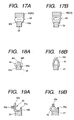
- Figs, 17A and 17B show a first modification of the tube.
- legs 43a are provided on the lower surface of a tube 43. Those legs hold the tube fixing plate 31 therebetween.
- an inner face of the tube which is defined between the legs 43a, is fastened to the tube fixing plate 31 by adhesive.
- the upper wall of the tube 43 is bonded to the tube pressing plate 23 (40) by adhesive.
- the legs 43a for holding the timing belt 3 are provided on the lower surface of the tube 43. Accordingly, the tube 43 can be firmly fixed.
- FIG. 18A and 18B A second modification of the tube is shown in Figs. 18A and 18B.
- the tube 44 is integrally formed on the upper part of the tube fixing plate 31 by one piece molding. Specifically, the inner wall 44a of the tube 44 is integral with the upper side wall of the tube fixing plate 31. The inner bottom wall 44bof the tube 44 is separable from the upper surface of the tube fixing plate 31.
- a hook 44c is formed an the upper surface (upper wall) of the tube 44. The hook is fixed to a protrusion (not shown) formed on the lower surface of the tube pressing plate.
- the tube 44 when the hook 44c is pulled up, the tube 44 takes the form of a tube with a passage formed therein.
- the hook 44c is returned to the original position, the tube 44 is deformed to be closed in the passage or flat as shown in Fig. 18A.
- the tube44 in forming the tube fixing plate 31, the tube44 is also formed together with it by one piece molding. Accordingly, the manufacturing cost of the tube is reduced. There is no need for the bonding work of bonding the tube fixing plate 31 to the tube.
- FIGs. 19A and 19B A third modification of the tube is shown in Figs. 19A and 19B.
- the tube 45 is shaped like L.
- its upright portion 45a is curvedly bent and its top end is bonded to a bottom 45b by adhesive.
- the bottom 45b of the tube 45 is fixed to the upper surface of the tube fixing plate 31.
- the upright portion 45a of the tube 45 is curvedly bent and the top end of the upright portion 45a is bonded to the bottom 45b by adhesive, whereby the tube 45 is formed.
- a hook 45c is formed on the upper surface (upper wall) of the tube 44.
- the hook is fastened to a protrusion (not shown) provided on the lower surface of the tube pressing plate.
- the hook 45c is fixed integral with the tube 45.
- the tube fixing plate 31 includes a holder portion 31 a which holds the tip of the upright portion 45a.
- the end of the upright portion 45a is inserted into a space between the holder portion 31a and the bottom 45b, and the end of the upright portion 45a is bonded to the bottom 45b by adhesive.
- the end of the upright portion 45a may be press fit into the space between the holder portion 31 a and the bottom 45b, instead.
- the holder portion 31 a, the end of the upright portion 45a and the bottom 45b are bonded together by adhesive.
- the tube is firmly fixed to the tube fixing plate 31.
- a fourth modification of the tube shown in Figs. 20A and 20B is a flat tube 46.
- the tube is formed on the upper surface of the tube fixing plate 31 in a unitary fashion.
- Bottom side parts 46a of the flat tube 46 are integral with the tube fixing plate 31.
- a central portion 46b of the flat tube 46 is separable from the upper surface of the tube fixing plate 31.
- the upper surface of the flat tube 46 is secured to the lower surface of the tube pressing plate 40.
- a fluid passage is formed between the flat tube 46 and the tube fixing plate 31.
- the tube pressing plate 40 (23) swings, the flat tube 46 is gradually pressed to be flat, and takes again its initial shape.
- the guide member 4 is formed by one piece molding, and accordingly, its manufacturing cost is low.
- a lower wall 47b of a tube 47 shown in Fig. 21, which is a fifth modification of the tube, is formed integral with the upper surface of the tube fixing plate 31 by one piece molding.
- An upper wall 47a of the tube 47 is formed integral with the lower surface of the tube pressing plate 40, by one piece molding.
- the upper wall 47a and the lower wall 47b of the tube 47 are bonded together by adhesive. Then, those walls 47a and 47b are clamped together by fastening member 48a. in this case, the upper and lower walls 47a and 47b, and the fastening member 48a are preferably bonded by adhesive. if required, those walls 47a and 47b may be brought into press contact with each other by the fastening member 48a, instead.
- the tube 47 is formed by bonding together the upper and lower walls 47a and 47b by adhesive. Through a swing motion of the tube pressing plate 40, the tube 47 is gradually pressed flat and is returned to its initial state.
- the upper and lower walls 47a and 47b are also molded together with those plates by one piece molding. Accordingly, the manufacturing cost is low.
- the present invention is applied to the ink jet recording apparatus which uses a tube pump for restoring the ink-ejection capability
- the invention may be applied to other types of ink jet recording apparatus.
- An example of such is an ink jet recording apparatus in which the tube pump is used for an ink supplier for supplying ink from a main tank to a sub-tank.
- the tube pressing operation by pressing a part of the tube and the tube restoring operation are concurrently performed.
- the invention may be applied to a case where both the operations are not concurrently performed. In this case, the tube is not constantly pressed. Therefore, it is necessary to prevent a backward flow of ink in the ink passage.
- a check valve (not shown) is provided between the tube pump and the capping unit or between tube pump and a waste ink tank.
- a check valve (not shown) is provided between the main tank and the tube pump or between the tube pump and the subtank.
- the ink jet recording apparatus uses a single tube pump, it should be understood that the invention may be applied to an ink jet recording apparatus using a plurality of tube pumps.
Landscapes
- Engineering & Computer Science (AREA)
- Mechanical Engineering (AREA)
- General Engineering & Computer Science (AREA)
- Reciprocating Pumps (AREA)
- Ink Jet (AREA)
- Details Of Reciprocating Pumps (AREA)
Claims (12)
- Pompe tubulaire (11), comprenant :un arbre d'entraînement (21) ;un rotor (22) fixé à l'arbre d'entraînement de manière à tourner avec celui-ci, le rotor consistant en un élément de disque rotatif (22) ;un élément presse-tube (23) pouvant pivoter dans une direction axiale de l'arbre d'entraînement, l'élément presse-tube consistant en un élément de plaque (23) qui est opposé au rotor ;un élément de pivotement (37) destiné à faire pivoter l'élément presse-tube conformément à la rotation du rotor ;un tube (25, 43, 44, 45, 46, 47) dont une face supérieure extérieure est fixée à une partie inférieure de l'élément presse-tube ; etun élément de fixation (31) auquel une face inférieure extérieure du tube est fixée,le tube subissant une pression et une expansion de manière forcée conformément au mouvement de pivotement de l'élément presse-tube tandis que la partie pressée/expansée est mue dans la direction d'expansion,caractérisée en ce que
l'élément de pivotement comprend :un élément de ressort (37b) dont une extrémité est fixée à l'élément de disque rotatif ;un corps de bille (37d) déplaçable sur une face supérieure de l'élément presse-tube ; etun support (37c) auquel l'autre extrémité de l'élément de ressort est fixé, ce support servant à supporter le corps de bille. - Pompe tubulaire selon la revendication 1, dans laquelle un trou traversant (23d) formé sur une partie centrale de l'élément presse-tube (23) sert à l'insertion de l'arbre d'entraînement ;
le diamètre du trou traversant étant supérieur au diamètre de l'arbre d'entraînement ; et
un élément cylindrique (23e) étant formé sur une face inférieure de la plaque presse-tube de sorte à délimiter le trou traversant. - Pompe tubulaire selon la revendication 1 ou 2, dans laquelle le tube est fixé à l'élément presse-tube et à l'élément de fixation par adhésif ou par soudure.
- Pompe tubulaire selon l'une quelconque des revendications 1 à 3, dans laquelle l'élément presse-tube, le tube et l'élément de fixation sont formés d'un seul tenant.
- Pompe tubulaire selon l'une quelconque des revendications précédentes, dans laquelle le tube et l'élément de fixation sont formés d'un seul tenant ; et
dans laquelle un élément de crochet (44c, 45c) est formé sur la face supérieure extérieure du tube et est en prise avec un élément d'engagement formé sur la partie inférieure de l'élément presse-tube. - Pompe tubulaire selon l'une quelconque des revendications 1 à 5, dans laquelle le tube (47) comprend une partie supérieure de tube (47a) et une partie inférieure de tube (47b) qui sont connectées pour former un tube ;
une face supérieure de la partie supérieure de tube et l'élément presse-tube (40) étant formés d'un seul tenant ; et
une face inférieure de la partie inférieure de tube et l'élément de fixation (31) étant formés d'un seul tenant. - Pompe tubulaire selon l'une quelconque des revendications 1 à 5, dans laquelle l'élément presse-tube (23) est muni d'un trou destiné à recevoir une saillie (25a) formée sur la face supérieure extérieure du tube (25) ; et
dans laquelle l'élément de fixation est muni d'un trou destiné à recevoir une saillie (25b) formée sur la face inférieure extérieure du tube. - Pompe tubulaire selon l'une quelconque des revendications précédentes, dans laquelle l'élément presse-tube exerce toujours une pression sur au moins une partie du tube.
- Appareil d'enregistrement à jet d'encre, comprenant :une tête d'enregistrement (7) munie d'une face (a) à formation de buses qui éjectent des gouttes d'encre conformément à des données d'impression ;une unité de recouvrement (10) destinée à fermer la face à formation de buses ; etune unité de pompe destinée à exercer une dépression sur l'unité de recouvrement pour aspirer l'encre de la tête d'enregistrement, l'unité de pompe comprenant la pompe tubulaire selon l'une quelconque des revendications 1 à 8.
- Appareil d'enregistrement à jet d'encre, comprenant :une tête d'enregistrement (7) de laquelle des gouttes d'encre sont éjectées conformément à des données d'impression ;un réservoir principal destiné à contenir l'encre devant être éjectée par la tête d'enregistrement ; etun distributeur d'encre destiné à distribuer de l'encre du réservoir principal à un sous-réservoir muni de la tête d'enregistrement, le distributeur d'encre comprenant la pompe tubulaire selon l'une quelconque des revendications 1 à 8.
- Appareil d'enregistrement selon la revendication 9, dans lequel l'unité de pompe est munie d'un clapet anti-retour.
- Appareil d'enregistrement selon la revendication 10, comprenant en outre un clapet anti-retour prévu dans le passage de distribution d'encre entre le réservoir principal et le sous-réservoir, le passage de distribution d'encre comprenant le distributeur d'encre.
Applications Claiming Priority (8)
| Application Number | Priority Date | Filing Date | Title |
|---|---|---|---|
| JP2000036734 | 2000-02-15 | ||
| JP2000036734 | 2000-02-15 | ||
| JP2000149712A JP3573059B2 (ja) | 2000-05-22 | 2000-05-22 | チューブポンプおよびこれを用いたインクジェット式記録装置 |
| JP2000149712 | 2000-05-22 | ||
| JP2000352478A JP3767735B2 (ja) | 2000-11-20 | 2000-11-20 | チューブポンプおよびこれを用いたインクジェット式記録装置 |
| JP2000352478 | 2000-11-20 | ||
| JP2001011437A JP3951094B2 (ja) | 2000-02-15 | 2001-01-19 | チューブポンプおよびこれを用いたインクジェット式記録装置 |
| JP2001011437 | 2001-01-19 |
Publications (3)
| Publication Number | Publication Date |
|---|---|
| EP1126172A2 EP1126172A2 (fr) | 2001-08-22 |
| EP1126172A3 EP1126172A3 (fr) | 2003-11-19 |
| EP1126172B1 true EP1126172B1 (fr) | 2006-09-27 |
Family
ID=27481034
Family Applications (1)
| Application Number | Title | Priority Date | Filing Date |
|---|---|---|---|
| EP01103515A Expired - Lifetime EP1126172B1 (fr) | 2000-02-15 | 2001-02-15 | Pompe péristaltique pour une imprimante à jet d'encre |
Country Status (4)
| Country | Link |
|---|---|
| US (1) | US6599106B2 (fr) |
| EP (1) | EP1126172B1 (fr) |
| AT (1) | ATE340933T1 (fr) |
| DE (1) | DE60123302T2 (fr) |
Families Citing this family (12)
| Publication number | Priority date | Publication date | Assignee | Title |
|---|---|---|---|---|
| JP4690034B2 (ja) * | 2004-12-28 | 2011-06-01 | エスアイアイ・プリンテック株式会社 | チューブポンプ、インクジェット記録装置、及びインク供給方法 |
| JP5177978B2 (ja) * | 2006-08-23 | 2013-04-10 | キヤノン株式会社 | インクジェット記録装置 |
| JP5379361B2 (ja) * | 2007-08-08 | 2013-12-25 | 出光興産株式会社 | 耐摩耗剤、潤滑剤用添加剤組成物及び潤滑油組成物 |
| US9359529B2 (en) * | 2008-10-29 | 2016-06-07 | 3M Innovative Properties Company | Electron beam cured silicone materials |
| JP5440147B2 (ja) * | 2009-12-17 | 2014-03-12 | 株式会社リコー | 画像形成装置、ポンプ制御方法、及びプログラム |
| US20110279581A1 (en) * | 2010-05-17 | 2011-11-17 | Silverbrook Research Pty Ltd | Multi-channel rotary valve for printhead |
| JP2011255642A (ja) * | 2010-06-11 | 2011-12-22 | Seiko Epson Corp | 流体噴射装置 |
| TW201332818A (zh) * | 2011-09-07 | 2013-08-16 | Gojo Ind Inc | 刮刷器泡沫泵,再填充單元,及用於刮刷器泡沫泵之分配器 |
| JP5982855B2 (ja) * | 2012-02-17 | 2016-08-31 | セイコーエプソン株式会社 | 流体輸送装置、交換ユニット、及び交換ユニットの製造方法 |
| CN103147962B (zh) * | 2013-03-13 | 2015-09-02 | 肖立峰 | 由圆锥摆动推力轴驱动的隔膜泵 |
| WO2016184918A1 (fr) * | 2015-05-18 | 2016-11-24 | Smith & Nephew Plc | Systèmes de pompe thermo-assistés pour utilisation dans le traitement des plaies par pression négative |
| DE102016102995A1 (de) * | 2016-02-19 | 2017-08-24 | Helmut Hechinger Gmbh & Co. Kg | Schlauchpumpe |
Family Cites Families (11)
| Publication number | Priority date | Publication date | Assignee | Title |
|---|---|---|---|---|
| GB484479A (en) * | 1936-11-02 | 1938-05-02 | Charles Bell Walker | Improvements in pumps |
| US2917002A (en) * | 1956-11-23 | 1959-12-15 | Mascaro Anthony | Pump |
| NL6505281A (fr) * | 1965-04-26 | 1966-10-27 | ||
| DE2126260A1 (de) * | 1970-06-02 | 1971-12-16 | VEB Kombinat Medizin- und Labortechnik, χ 7035 Leipzig | Schlauchpumpe mit einstellbarer Fördermenge |
| DE2708277A1 (de) * | 1977-02-25 | 1978-08-31 | Nikkiso Eiko Kk | Verdraengungspumpe |
| US4315718A (en) * | 1979-09-17 | 1982-02-16 | Cole-Parmer Instrument Company | Peristaltic pump and bearing arrangement therefor |
| JP2801388B2 (ja) * | 1989-10-22 | 1998-09-21 | キヤノン株式会社 | インクジェット記録装置の回復方法 |
| FR2690621B1 (fr) * | 1992-04-29 | 1995-02-10 | Chronotec | Système de pompe à perfusion sans frottements. |
| JPH11190279A (ja) * | 1997-12-25 | 1999-07-13 | Canon Inc | チューブポンプおよびインクジェット記録装置 |
| US6264438B1 (en) * | 1998-02-10 | 2001-07-24 | Ohken Seiko Co., Ltd. | Reciprocating pump having a ball drive |
| US6296460B1 (en) * | 2000-03-01 | 2001-10-02 | Steve C. Smith | Rotary cavity pump |
-
2001
- 2001-02-15 AT AT01103515T patent/ATE340933T1/de not_active IP Right Cessation
- 2001-02-15 US US09/783,125 patent/US6599106B2/en not_active Expired - Fee Related
- 2001-02-15 EP EP01103515A patent/EP1126172B1/fr not_active Expired - Lifetime
- 2001-02-15 DE DE60123302T patent/DE60123302T2/de not_active Expired - Lifetime
Also Published As
| Publication number | Publication date |
|---|---|
| DE60123302T2 (de) | 2007-05-10 |
| EP1126172A3 (fr) | 2003-11-19 |
| EP1126172A2 (fr) | 2001-08-22 |
| US6599106B2 (en) | 2003-07-29 |
| ATE340933T1 (de) | 2006-10-15 |
| US20010019344A1 (en) | 2001-09-06 |
| DE60123302D1 (de) | 2006-11-09 |
Similar Documents
| Publication | Publication Date | Title |
|---|---|---|
| US6364449B1 (en) | Ink jet recording apparatus and cleaning control method for the same | |
| EP1126172B1 (fr) | Pompe péristaltique pour une imprimante à jet d'encre | |
| WO2001053103A1 (fr) | Cartouche d'encre, dispositif enregistreur a jet encre utilisant cette cartouche et procede de commande de nettoyage pour tete enregistreuse du dispositif enregistreur | |
| JP3173556B2 (ja) | インクジェット記録装置 | |
| JP3285074B2 (ja) | インクジェット式記録装置 | |
| JP3658287B2 (ja) | 回復ユニット及び該回復ユニットを用いるインクジェット記録装置 | |
| US6883896B2 (en) | Ink jet recording apparatus | |
| JP2000153622A (ja) | インクジェット式記録装置およびこれに適したクリ―ニング方法 | |
| JP2840409B2 (ja) | インクジェット記録ヘッド及びインクジェット記録装置 | |
| JP3951094B2 (ja) | チューブポンプおよびこれを用いたインクジェット式記録装置 | |
| JP2003048328A (ja) | インクタンク及び該インクタンクを備えたインクジェット記録装置。 | |
| JP3664213B2 (ja) | チューブポンプおよびこれを用いたインクジェット式記録装置 | |
| JP2003266734A (ja) | インクジェット記録装置およびインク供給方法 | |
| US20030234829A1 (en) | Liquid jetting apparatus | |
| JP3765361B2 (ja) | インクジェット式記録装置 | |
| JP3573059B2 (ja) | チューブポンプおよびこれを用いたインクジェット式記録装置 | |
| JP2002180968A (ja) | ポンプ機構及び該ポンプ機構を用いるインクジェット記録装置 | |
| JP2693229B2 (ja) | インクジェット記録装置およびインク吸引ポンプ | |
| JP2000289225A (ja) | インクジェット記録装置、この装置に用いられるバルブユニット、この装置におけるインク吸引方法、並びにこのバルブユニットを用いたインクジェット式記録ヘッドのクリ−ニング方法 | |
| JP2001193670A (ja) | チューブポンプおよびこれを用いたインクジェット式記録装置 | |
| JPH1120182A (ja) | インクカートリッジ | |
| JP3189895B2 (ja) | インクジェット式記録装置 | |
| JP2954038B2 (ja) | インク吸引手段 | |
| JP3767735B2 (ja) | チューブポンプおよびこれを用いたインクジェット式記録装置 | |
| JPH03234638A (ja) | インクジェット記録装置 |
Legal Events
| Date | Code | Title | Description |
|---|---|---|---|
| PUAI | Public reference made under article 153(3) epc to a published international application that has entered the european phase |
Free format text: ORIGINAL CODE: 0009012 |
|
| AK | Designated contracting states |
Kind code of ref document: A2 Designated state(s): AT BE CH CY DE DK ES FI FR GB GR IE IT LI LU MC NL PT SE TR |
|
| AX | Request for extension of the european patent |
Free format text: AL;LT;LV;MK;RO;SI |
|
| PUAL | Search report despatched |
Free format text: ORIGINAL CODE: 0009013 |
|
| AK | Designated contracting states |
Kind code of ref document: A3 Designated state(s): AT BE CH CY DE DK ES FI FR GB GR IE IT LI LU MC NL PT SE TR |
|
| AX | Request for extension of the european patent |
Extension state: AL LT LV MK RO SI |
|
| 17P | Request for examination filed |
Effective date: 20040116 |
|
| 17Q | First examination report despatched |
Effective date: 20040422 |
|
| AKX | Designation fees paid |
Designated state(s): AT BE CH CY DE DK ES FI FR GB GR IE IT LI LU MC NL PT SE TR |
|
| GRAP | Despatch of communication of intention to grant a patent |
Free format text: ORIGINAL CODE: EPIDOSNIGR1 |
|
| GRAS | Grant fee paid |
Free format text: ORIGINAL CODE: EPIDOSNIGR3 |
|
| GRAA | (expected) grant |
Free format text: ORIGINAL CODE: 0009210 |
|
| AK | Designated contracting states |
Kind code of ref document: B1 Designated state(s): AT BE CH CY DE DK ES FI FR GB GR IE IT LI LU MC NL PT SE TR |
|
| PG25 | Lapsed in a contracting state [announced via postgrant information from national office to epo] |
Ref country code: LI Free format text: LAPSE BECAUSE OF FAILURE TO SUBMIT A TRANSLATION OF THE DESCRIPTION OR TO PAY THE FEE WITHIN THE PRESCRIBED TIME-LIMIT Effective date: 20060927 Ref country code: IT Free format text: LAPSE BECAUSE OF FAILURE TO SUBMIT A TRANSLATION OF THE DESCRIPTION OR TO PAY THE FEE WITHIN THE PRESCRIBED TIME-LIMIT;WARNING: LAPSES OF ITALIAN PATENTS WITH EFFECTIVE DATE BEFORE 2007 MAY HAVE OCCURRED AT ANY TIME BEFORE 2007. THE CORRECT EFFECTIVE DATE MAY BE DIFFERENT FROM THE ONE RECORDED. Effective date: 20060927 Ref country code: NL Free format text: LAPSE BECAUSE OF FAILURE TO SUBMIT A TRANSLATION OF THE DESCRIPTION OR TO PAY THE FEE WITHIN THE PRESCRIBED TIME-LIMIT Effective date: 20060927 Ref country code: CH Free format text: LAPSE BECAUSE OF FAILURE TO SUBMIT A TRANSLATION OF THE DESCRIPTION OR TO PAY THE FEE WITHIN THE PRESCRIBED TIME-LIMIT Effective date: 20060927 Ref country code: AT Free format text: LAPSE BECAUSE OF FAILURE TO SUBMIT A TRANSLATION OF THE DESCRIPTION OR TO PAY THE FEE WITHIN THE PRESCRIBED TIME-LIMIT Effective date: 20060927 Ref country code: FI Free format text: LAPSE BECAUSE OF FAILURE TO SUBMIT A TRANSLATION OF THE DESCRIPTION OR TO PAY THE FEE WITHIN THE PRESCRIBED TIME-LIMIT Effective date: 20060927 Ref country code: BE Free format text: LAPSE BECAUSE OF FAILURE TO SUBMIT A TRANSLATION OF THE DESCRIPTION OR TO PAY THE FEE WITHIN THE PRESCRIBED TIME-LIMIT Effective date: 20060927 |
|
| REG | Reference to a national code |
Ref country code: GB Ref legal event code: FG4D |
|
| REG | Reference to a national code |
Ref country code: CH Ref legal event code: EP |
|
| REG | Reference to a national code |
Ref country code: IE Ref legal event code: FG4D |
|
| REF | Corresponds to: |
Ref document number: 60123302 Country of ref document: DE Date of ref document: 20061109 Kind code of ref document: P |
|
| PG25 | Lapsed in a contracting state [announced via postgrant information from national office to epo] |
Ref country code: SE Free format text: LAPSE BECAUSE OF FAILURE TO SUBMIT A TRANSLATION OF THE DESCRIPTION OR TO PAY THE FEE WITHIN THE PRESCRIBED TIME-LIMIT Effective date: 20061227 Ref country code: DK Free format text: LAPSE BECAUSE OF FAILURE TO SUBMIT A TRANSLATION OF THE DESCRIPTION OR TO PAY THE FEE WITHIN THE PRESCRIBED TIME-LIMIT Effective date: 20061227 |
|
| PG25 | Lapsed in a contracting state [announced via postgrant information from national office to epo] |
Ref country code: ES Free format text: LAPSE BECAUSE OF FAILURE TO SUBMIT A TRANSLATION OF THE DESCRIPTION OR TO PAY THE FEE WITHIN THE PRESCRIBED TIME-LIMIT Effective date: 20070107 |
|
| PG25 | Lapsed in a contracting state [announced via postgrant information from national office to epo] |
Ref country code: MC Free format text: LAPSE BECAUSE OF NON-PAYMENT OF DUE FEES Effective date: 20070228 |
|
| NLV1 | Nl: lapsed or annulled due to failure to fulfill the requirements of art. 29p and 29m of the patents act | ||
| PG25 | Lapsed in a contracting state [announced via postgrant information from national office to epo] |
Ref country code: PT Free format text: LAPSE BECAUSE OF FAILURE TO SUBMIT A TRANSLATION OF THE DESCRIPTION OR TO PAY THE FEE WITHIN THE PRESCRIBED TIME-LIMIT Effective date: 20070313 |
|
| REG | Reference to a national code |
Ref country code: CH Ref legal event code: PL |
|
| ET | Fr: translation filed | ||
| PLBE | No opposition filed within time limit |
Free format text: ORIGINAL CODE: 0009261 |
|
| STAA | Information on the status of an ep patent application or granted ep patent |
Free format text: STATUS: NO OPPOSITION FILED WITHIN TIME LIMIT |
|
| 26N | No opposition filed |
Effective date: 20070628 |
|
| PG25 | Lapsed in a contracting state [announced via postgrant information from national office to epo] |
Ref country code: IE Free format text: LAPSE BECAUSE OF NON-PAYMENT OF DUE FEES Effective date: 20070215 |
|
| PG25 | Lapsed in a contracting state [announced via postgrant information from national office to epo] |
Ref country code: GR Free format text: LAPSE BECAUSE OF FAILURE TO SUBMIT A TRANSLATION OF THE DESCRIPTION OR TO PAY THE FEE WITHIN THE PRESCRIBED TIME-LIMIT Effective date: 20061228 |
|
| PG25 | Lapsed in a contracting state [announced via postgrant information from national office to epo] |
Ref country code: CY Free format text: LAPSE BECAUSE OF FAILURE TO SUBMIT A TRANSLATION OF THE DESCRIPTION OR TO PAY THE FEE WITHIN THE PRESCRIBED TIME-LIMIT Effective date: 20060927 Ref country code: LU Free format text: LAPSE BECAUSE OF NON-PAYMENT OF DUE FEES Effective date: 20070215 |
|
| PG25 | Lapsed in a contracting state [announced via postgrant information from national office to epo] |
Ref country code: TR Free format text: LAPSE BECAUSE OF FAILURE TO SUBMIT A TRANSLATION OF THE DESCRIPTION OR TO PAY THE FEE WITHIN THE PRESCRIBED TIME-LIMIT Effective date: 20060927 |
|
| PGFP | Annual fee paid to national office [announced via postgrant information from national office to epo] |
Ref country code: FR Payment date: 20130301 Year of fee payment: 13 Ref country code: GB Payment date: 20130213 Year of fee payment: 13 Ref country code: DE Payment date: 20130213 Year of fee payment: 13 |
|
| REG | Reference to a national code |
Ref country code: DE Ref legal event code: R119 Ref document number: 60123302 Country of ref document: DE |
|
| GBPC | Gb: european patent ceased through non-payment of renewal fee |
Effective date: 20140215 |
|
| REG | Reference to a national code |
Ref country code: FR Ref legal event code: ST Effective date: 20141031 |
|
| REG | Reference to a national code |
Ref country code: DE Ref legal event code: R119 Ref document number: 60123302 Country of ref document: DE Effective date: 20140902 |
|
| PG25 | Lapsed in a contracting state [announced via postgrant information from national office to epo] |
Ref country code: FR Free format text: LAPSE BECAUSE OF NON-PAYMENT OF DUE FEES Effective date: 20140228 Ref country code: DE Free format text: LAPSE BECAUSE OF NON-PAYMENT OF DUE FEES Effective date: 20140902 Ref country code: GB Free format text: LAPSE BECAUSE OF NON-PAYMENT OF DUE FEES Effective date: 20140215 |