EP1120312B1 - Aussenrückblickspiegel für Fahrzeuge, vorzugsweise für Kraftfahrzeuge - Google Patents
Aussenrückblickspiegel für Fahrzeuge, vorzugsweise für Kraftfahrzeuge Download PDFInfo
- Publication number
- EP1120312B1 EP1120312B1 EP01101476A EP01101476A EP1120312B1 EP 1120312 B1 EP1120312 B1 EP 1120312B1 EP 01101476 A EP01101476 A EP 01101476A EP 01101476 A EP01101476 A EP 01101476A EP 1120312 B1 EP1120312 B1 EP 1120312B1
- Authority
- EP
- European Patent Office
- Prior art keywords
- rear view
- lamp
- view mirror
- exterior rear
- mirror according
- Prior art date
- Legal status (The legal status is an assumption and is not a legal conclusion. Google has not performed a legal analysis and makes no representation as to the accuracy of the status listed.)
- Expired - Lifetime
Links
Images


Classifications
-
- B—PERFORMING OPERATIONS; TRANSPORTING
- B60—VEHICLES IN GENERAL
- B60Q—ARRANGEMENT OF SIGNALLING OR LIGHTING DEVICES, THE MOUNTING OR SUPPORTING THEREOF OR CIRCUITS THEREFOR, FOR VEHICLES IN GENERAL
- B60Q1/00—Arrangement of optical signalling or lighting devices, the mounting or supporting thereof or circuits therefor
- B60Q1/26—Arrangement of optical signalling or lighting devices, the mounting or supporting thereof or circuits therefor the devices being primarily intended to indicate the vehicle, or parts thereof, or to give signals, to other traffic
- B60Q1/2661—Arrangement of optical signalling or lighting devices, the mounting or supporting thereof or circuits therefor the devices being primarily intended to indicate the vehicle, or parts thereof, or to give signals, to other traffic mounted on parts having other functions
- B60Q1/2665—Arrangement of optical signalling or lighting devices, the mounting or supporting thereof or circuits therefor the devices being primarily intended to indicate the vehicle, or parts thereof, or to give signals, to other traffic mounted on parts having other functions on rear-view mirrors
-
- B—PERFORMING OPERATIONS; TRANSPORTING
- B60—VEHICLES IN GENERAL
- B60R—VEHICLES, VEHICLE FITTINGS, OR VEHICLE PARTS, NOT OTHERWISE PROVIDED FOR
- B60R1/00—Optical viewing arrangements; Real-time viewing arrangements for drivers or passengers using optical image capturing systems, e.g. cameras or video systems specially adapted for use in or on vehicles
- B60R1/12—Mirror assemblies combined with other articles, e.g. clocks
- B60R1/1207—Mirror assemblies combined with other articles, e.g. clocks with lamps; with turn indicators
Definitions
- the invention relates to an exterior rearview mirror for vehicles, preferably for motor vehicles, according to the preamble of claim 1.
- a repeating indicator is housed. She makes sure that also by the side of the vehicle located road users by Turn on the repeating flashlight can reliably detect that the vehicle turns off.
- EP 0 941 892 A are located behind a lens LEDs, which are in openings of a cover protrude, which is provided behind the lens.
- EP 0 941 892 A is located behind a lens LEDs, which are in openings of a cover protrude, which is provided behind the lens.
- Another Version is located behind the bulb a reflector.
- an external rearview mirror is known (EP 0 896 898 A), which has a lighting unit. She has a lens, behind which is a Reflector is located, which has openings in its center through which Bulbs protrude.
- the invention is based on the object, the generic exterior rearview mirror form so that the lighting unit with simple constructive Training the exterior rearview mirror reliably their lighting function Fulfills.
- the light source is in Area of the opening provided in the reflector.
- the light bulb can be arranged in the opening of the reflector so that it from outside through the lens is not recognizable.
- the reflector ensures that the not directly to the lens reaching rays of the bulb for Lens are reflected back.
- the opening is at an angle to the lens lying wall of the reflector provided. ing rays of the light source reflected towards the lens become.
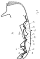
- the exterior rear view mirror described below is for vehicles, in particular motor vehicles, provided. He has a mirror head 1, which in a known manner with a (not shown) Mirror is hinged hinged.
- the mirror head 1 can in Direction of travel can be folded forwards and backwards.
- the mirror head 1 has a housing 2, which is advantageously made of plastic and an opening on its rear facing the rear in the direction of travel 3 for the (not shown) mirror glass carrier with the mirror glass having.
- This mirror glass carrier is on a support 4 in known way adjustable, the inside of the housing. 2 is housed.
- the mirror glass carrier is motor-adjustable.
- the corresponding drive motor (not shown) is on the carrier 4 stored.
- the forward in the direction of travel F front 5 of the housing 2 is formed with a recess formed in the form of a recess 6 provided (Fig. 1 and 3), in which serving as a flashing light Lamp unit 7 is inserted.
- the recording is 6 approximately halfway up the front side 5 of the mirror head housing 2. From Fig. 1 it follows that the recording 6 more than the half width of the mirror head 1 close to that of the motor vehicle remote outer edge 8 of the housing 2 extends.
- the recording 6, which is open to the front 5 of the mirror head 1 has at least over part of its length a bottom 9 (FIG. 3), the via side walls 10, 11 merges into the front wall 5 of the housing 2.
- the bottom 9 and the side walls 10, 11 of the Recording 6 integrally formed with the housing 2.
- the lamp unit 7 has a lamp housing 12, which in its Outline shape adapted approximately to the cross-sectional education of the recording 6 is.
- the luminaire housing 12 is on its front wall. 5 of the housing 2 side facing closed by a lens 13. Its edge 14 is inward toward the receptacle 6 angled.
- the lens 13 is made of transparent material and may be internally provided with lenses 15 ( Figure 2).
- peripheral edge 14 is the lens 13 attached to the edge of the lamp housing 12, for example with welded him.
- the lens 13 and the lamp housing 12th are advantageously made of plastic.
- the luminaire housing 12 protrudes with a projection 16 (FIG. 1) through a Opening 17 in the side wall of the receptacle 6 and the carrier. 4 in the housing 2 enclosed by the interior 18 of the mirror head 1.
- the projection 16 is facing at the mirror base Narrow side of the elongated lamp housing 12 is provided and preferably formed integrally with it.
- a plug 19 is provided, via which the lamp unit 7 with the necessary power is supplied.
- the projection 16 is located on a seal 20, which is provided on the inside of the housing 2 and preferably on a projecting from the inside of the housing Rib 21 is arranged.
- the luminaire housing 12 has for this purpose at its the Carrier 4 facing the back of a projection 23, preferably formed integrally with the lamp housing 12 and on the one end of a clip spring 24 is attached.
- the other end 25 of the clip spring 24 is hook-shaped and engages in the installation position of the lamp unit 7 under elastic deformation a hook-shaped projection 26 which at the bottom 9 of the receptacle is provided.
- the luminaire housing 12 is formed in a longitudinal section according to FIG. 1 in such a way that that there are several, in the exemplary embodiment three projections 27th to 29, which are formed in cross-section V-shaped and through a corresponding shape of the lamp housing 12 is formed are. Between the lamp housing 12 and the lens 13th there is a reflector 30, which emitted by bulbs 31 Light reflected to the lens 13. In Fig. 1 are exemplary the beams 32 of the lamps 31 are shown. The bulbs 31 are held on the lamp housing 12 and are advantageous by LEDs formed.
- the arrangement of the lamps 31 is based on Fig. 2 explained in more detail.
- the LEDs 31 are acute at the two attached to each other sides 33, 34 of the projection 28.
- the reflector 30 has a recess 35, which is bounded by a bottom 36 and side walls 37, 38.
- the side walls 37, 38 spaced from the sides 33, 34 of the Projection 28 are located, there are openings 39, 40, through which the bulbs 31 partially protrude.
- the bottom 36 of the recess 35 is located at a small distance in front of the projection 28 and covers this against the lens 13. The bottom 36 thus forms a privacy shield, which prevents the projection 28 of the Luminaire housing 12 from the outside through the lens 13 recognizable is.
- the lamp housing 12 Since the lamp housing 12 more, over the length of the lamp unit 7 distributed arranged bulbs 31, the Lens 13 evenly illuminated. With regard to the flashing function it is sufficient if the lamp housing 12 only in Area of the projection 27, which faces away from the motor vehicle End 8 of the mirror head 1 is provided with a Illuminant 31 is provided. As shown in FIG. 1, the outer Bulb 31 outgoing rays in the direction of travel F diagonally forward to obliquely radiated backwards. This allows the flashing light, when actuated by the driver of the motor vehicle, from other road users are recognized, in particular of those road users who are in the area next to the Stop the motor vehicle.
- the bottom 36 of the recesses 35 of the reflector 30 also prevents that the conductor foil 41 is visible through the lens 13, because he covers the conductor foil in the region of the projections 27 to 29.
- Fig. 4 shows an embodiment in which the reflector 30a instead that provided in the previous embodiment, in cross section V-shaped projection 27 has a bend 42. she has a transversely to the lens 13 extending wall 43, in which an opening 44 for the lamp 31 is located. It is advantageous an LED which lies in the opening 44 and whose rays through the Lens 13 fall laterally outward. Toward the lens 13, the lamp 31 is replaced by a part of the reflector Covered 30a, so that the rays emanating from the bulb mainly out to the side. Otherwise, the mirror head 1 a formed the same as in the previous embodiment.
- the Embodiment of FIG. 4 is characterized by its structurally simple Training out. While in the embodiment according to the Fig. 1 to 3 at each projection 27 to 29 two lamps 31 are provided are at the mirror head 1a of Fig. 4 only on the projections 28, 29 each two bulbs 31 arranged while at the end remote from the motor vehicle of the lamp unit 7a only one light source 31 is present.
- the conductor foil 41 is flexible, it can be easily on Apply the most varied luminaire housing. Of course can the bulbs 31 in other ways with be supplied with the necessary electricity. So instead of the conductor foil 41, for example, a MID (molded interconnected device) part can be used, to which the LEDs 31 are soldered. Another option is to attach and contact the LEDs 31 to use the known snap LED technology.
- the conductor foil 41 is located below a cover 45 which is attached to the lamp housing 12 is. Through the cover 45, the conductor foil 41 is reliable against Pollution, corrosion and the like protected.
- the cover 45 has, as Figs. 5 and 6 show, approximately the same cross-sectional shape as the lamp housing 12. In the area of the bulbs 31st the cover 45 is each provided with a molding 46, the into the openings 39, 40 of the recesses 35 of the reflector 30th pass. As a result, the bulbs 31 are protected under the Cover 45. It is at least in the area of the formations 46 translucent. Preferably, the entire cover 45 made of clear plastic. Moreover, the mirror head is the same as the embodiment of FIGS. 1 to 3.
- the cover 45 be provided to the conductor foil 41 and the bulbs 31 to protect.
- the cover 45 is preferably welded to the lamp housing 12, so that the conductor foil 41 with the bulbs 31 reliable is sealed.
- the lamp unit 7, 7a is a closed unit, which is simply insert into the receptacle 6 of the mirror head housing 2 leaves. Due to the clip connection 22, the lamp unit 7, 7a be easily replaced if necessary.
- the number of bulbs 31 may vary depending on the size of the lamp unit 7, 7a. she itself can have a variety of shapes, depending on the application.
Landscapes
- Engineering & Computer Science (AREA)
- Mechanical Engineering (AREA)
- Multimedia (AREA)
- Rear-View Mirror Devices That Are Mounted On The Exterior Of The Vehicle (AREA)
- Lighting Device Outwards From Vehicle And Optical Signal (AREA)
Description
- Fig. 1
- im Längsschnitt einen Spiegelkopf eines erfindungsgemäßen Außenrückblickspiegels,
- Fig. 2
- in vergrößerter Darstellung einen Ausschnitt des Spiegelkop- fes gemäß Fig. 1,
- Fig. 3
- einen Schnitt längs der Linie III-III in Fig. 1,
- Fig. 4
- in einer Darstellung entsprechend Fig. 1 eine zweite Ausfüh- rungsform eines Spiegelkopfes eines erfindungsgemäßen Außenrückblickspiegels,
- Fig. 5
- im Längsschnitt eine dritte Ausführungsform eines Spiegel- kopfes eines erfindungsgemäßen Außenrückblickspiegels,
- Fig. 6
- einen Querschnitt durch den Spiegelkopf gemäß Fig. 5.
Claims (13)
- Außenrückblickspiegel für Fahrzeuge, vorzugsweise für Kraftfahrzeuge, mit einem Gehäuse (2), das wenigstens eine Leuchteneinheit (7, 7a) aufnimmt, die mit mindestens einem Leuchtmittel (31) und mindestens einem Reflektor (30, 30a) versehen ist, der wenigstens eine Öffnung (39, 40, 44) aufweist, in deren Bereich das Leuchtmittel (31) liegt, dessen Strahlen (32) durch eine Lichtscheibe (13) nach außen treten,
dadurch gekennzeichnet, daß der Reflektor (30, 30a) zwischen dem Leuchtmittel (31) und der Lichtscheibe (13) liegt, und daß die Öffnung (39, 40, 44) in einer quer zur Lichtscheibe (13) sich erstreckenden Wand (37, 38, 43) des Reflektors (30, 30a) liegt. - Außenrückblickspiegel nach Anspruch 1,
dadurch gekennzeichnet, daß das Leuchtmittel (31) an einem Leuchtengehäuse (12) angeordnet ist. - Außenrückblickspiegel nach Anspruch 2.
dadurch gekennzeichnet, daß das Leuchtengehäuse (12) mit der Lichtscheibe (13) die geschlossene Leuchteneinheit (7, 7a) begrenzt. - Außenrückblickspiegel nach Anspruch 2 oder 3,
dadurch gekennzeichnet, daß das Leuchtengehäuse (12) wenigstens einen in Richtung auf die Lichtscheibe (13) gerichteten und vorteilhaft im Querschnitt V-förmigen Vorsprung (27 bis 29) aufweist. - Außenrückblickspiegel nach Anspruch 4,
dadurch gekennzeichnet, daß der Vorsprung (27 bis 29) in wenigstens eine Vertiefung (35) des Reflektors (30, 30a) ragt. - Außenrückblickspiegel nach Anspruch 5,
dadurch gekennzeichnet, daß die Vertiefung (35) die Öffnung (39, 40) aufweist. - Außenrückblickspiegel nach Anspruch 5 oder 6,
dadurch gekennzeichnet, daß die die Öffnung (39, 40, 44) aufweisende Wand (37, 38, 43) eine Seitenwand der Vertiefung (35) ist. - Außenrückblickspiegel nach einem der Ansprüche 5 bis 7,
dadurch gekennzeichnet, daß der Vorsprung (27 bis 29) des Reflektors (30, 30a) durch einen Boden (36) der Vertiefung (35) gegen die Lichtscheibe (13) abgedeckt ist. - Außenrückblickspiegel nach einem der Ansprüche 4 bis 8,
dadurch gekennzeichnet, daß der Vorsprung (27 bis 29) zwei winklig zueinander liegende Seitenwände (33, 34) aufweist, auf denen jeweils ein Leuchtmittel (31) sitzt. - Außenrückblickspiegel nach einem der Ansprüche 1 bis 9,
dadurch gekennzeichnet, daß die die Öffnung (44) aufweisende Wand (43) am vom Kraftfahrzeug entfernten Endbereich des Reflektors (30a) vorgesehen ist. - Außenrückblickspiegel nach einem der Ansprüche 1 bis 10,
dadurch gekennzeichnet, daß die Leuchteneinheit (7, 7a) lösbar am Spiegelkopf (1, 1 a) gehalten ist. - Außenrückblickspiegel nach einem der Ansprüche 1 bis 11,
dadurch gekennzeichnet, daß das Gehäuse (2) des Spiegelkopfes (1, 1a) eine vorteilhaft durch eine Einbuchtung des Gehäuses (2) des Spiegelkopfes (1, 1a) gebildete Aufnahme (6) für die Leuchteneinheit (7, 7a) aufweist. - Außenrückblickspiegel nach einem der Ansprüche 1 bis 12,
dadurch gekennzeichnet, daß das Leuchtmittel (31) eine LED ist.
Applications Claiming Priority (2)
| Application Number | Priority Date | Filing Date | Title |
|---|---|---|---|
| DE20001407U DE20001407U1 (de) | 2000-01-27 | 2000-01-27 | Außenrückblickspiegel für Fahrzeuge, vorzugsweise für Kraftfahrzeuge |
| DE20001407U | 2000-01-27 |
Publications (3)
| Publication Number | Publication Date |
|---|---|
| EP1120312A2 EP1120312A2 (de) | 2001-08-01 |
| EP1120312A3 EP1120312A3 (de) | 2004-01-02 |
| EP1120312B1 true EP1120312B1 (de) | 2005-10-19 |
Family
ID=7936460
Family Applications (1)
| Application Number | Title | Priority Date | Filing Date |
|---|---|---|---|
| EP01101476A Expired - Lifetime EP1120312B1 (de) | 2000-01-27 | 2001-01-24 | Aussenrückblickspiegel für Fahrzeuge, vorzugsweise für Kraftfahrzeuge |
Country Status (3)
| Country | Link |
|---|---|
| US (1) | US6695465B2 (de) |
| EP (1) | EP1120312B1 (de) |
| DE (2) | DE20001407U1 (de) |
Families Citing this family (45)
| Publication number | Priority date | Publication date | Assignee | Title |
|---|---|---|---|---|
| ES2168071B1 (es) | 2000-07-12 | 2003-07-16 | Barros Alejandro Rodriguez | Retrovisor modular con señales multiples intercambiables para vehiculos de 2, 3, 4 o mas ruedas. |
| DE50111625D1 (de) * | 2000-10-04 | 2007-01-25 | Fer Fahrzeugelektrik Gmbh | Seitenblinkleuchte |
| DE20017038U1 (de) | 2000-10-04 | 2001-01-11 | FER Fahrzeugelektrik GmbH, 99817 Eisenach | Seitenblinkleuchte |
| DE10054315B4 (de) * | 2000-11-02 | 2008-08-21 | Volkswagen Ag | Blinkleuchte |
| DE10058660B4 (de) * | 2000-11-25 | 2009-07-30 | Volkswagen Ag | Kraftfahrzeugleuchte |
| DE10058659B4 (de) * | 2000-11-25 | 2007-06-14 | Volkswagen Ag | Kraftfahrzeug-Leuchte, insbesondere Signalleuchte |
| WO2005017577A1 (en) * | 2002-12-23 | 2005-02-24 | Chan Sing Chiow Jack | Wide range rearview mirror with signal and safety lights |
| BR0212418A (pt) * | 2001-09-11 | 2004-08-03 | Thomson Licensing Sa | Método e aparelho para ativação de modo de equalização automática |
| DE10211189A1 (de) * | 2002-03-14 | 2003-10-09 | Schefenacker Vision Systems | Leuchteinheit, insbesondere als Zusatzeinheit in Außenrückblickspiegeln von Kraftfahrzeugen |
| DE20219483U1 (de) * | 2002-12-16 | 2003-05-08 | FER Fahrzeugelektrik GmbH, 99817 Eisenach | Fahrzeugleuchte |
| DE10258892A1 (de) * | 2002-12-17 | 2004-07-01 | Bayerische Motoren Werke Ag | Rückblickspiegel, insbesondere Außenrückblickspiegel, an einem Kraftfahrzeug |
| US20040145910A1 (en) * | 2003-01-29 | 2004-07-29 | Guide Corporation (A Delaware Corporation) | Lighting assembly |
| JP4110989B2 (ja) * | 2003-02-03 | 2008-07-02 | 市光工業株式会社 | ランプ付きアウトサイドミラー装置 |
| JP4262502B2 (ja) * | 2003-03-25 | 2009-05-13 | 株式会社ミツバ | サイドウインカー付きのドアミラー |
| DE102004018695A1 (de) * | 2003-12-05 | 2005-12-29 | Schefenacker Vision Systems Germany Gmbh | Außenrückblickspiegel für Fahrzeuge, vorzugsweise Kraftfahrzeuge |
| JP2005190716A (ja) * | 2003-12-24 | 2005-07-14 | Ichikoh Ind Ltd | 車両用アウトサイドミラー装置 |
| JP4433789B2 (ja) * | 2003-12-24 | 2010-03-17 | 市光工業株式会社 | 車両用アウトサイドミラー装置 |
| JP2005216831A (ja) * | 2004-02-02 | 2005-08-11 | Ichikoh Ind Ltd | 車両用アウトサイドミラー装置 |
| DE102004012052A1 (de) * | 2004-03-11 | 2005-10-06 | Fer Fahrzeugelektrik Gmbh | Seitenblinkleuchte |
| JP4321346B2 (ja) * | 2004-05-10 | 2009-08-26 | 市光工業株式会社 | 車両用アウトサイドミラー装置 |
| US7513664B2 (en) * | 2004-05-10 | 2009-04-07 | Ichikoh Industries, Ltd. | Outside mirror apparatus including lighting device for vehicle |
| US7591950B2 (en) * | 2004-11-02 | 2009-09-22 | Siemens Water Technologies Corp. | Submerged cross-flow filtration |
| EP1867912A4 (de) * | 2005-03-07 | 2009-05-13 | Furukawa Electric Co Ltd | Led-beleuchtungsvorrichtung |
| DE102005012104A1 (de) * | 2005-03-10 | 2006-09-14 | Schefenacker Vision Systems Germany Gmbh | Gehäuse, insbesondere Spiegelgehäuse |
| JP4594205B2 (ja) * | 2005-10-05 | 2010-12-08 | 本田技研工業株式会社 | 車両用方向指示灯 |
| JP4569444B2 (ja) * | 2005-11-09 | 2010-10-27 | 市光工業株式会社 | 車両用アウトサイドミラー装置 |
| US7467066B2 (en) * | 2006-05-05 | 2008-12-16 | International Business Machines Corporation | System and method for benchmarking correlated stream processing systems |
| DE102006025070A1 (de) * | 2006-05-23 | 2007-11-29 | Schefenacker Vision Systems Germany Gmbh | Außenspiegel eines Fahrzeugs |
| JP5004012B2 (ja) * | 2006-09-08 | 2012-08-22 | 本田技研工業株式会社 | 車両のウィンカ一体型バックミラー |
| JP2008097848A (ja) * | 2006-10-06 | 2008-04-24 | Ichikoh Ind Ltd | 車両用灯具 |
| JP4631838B2 (ja) * | 2006-10-20 | 2011-02-16 | 市光工業株式会社 | 車両用灯具 |
| JP4631840B2 (ja) * | 2006-11-02 | 2011-02-16 | 市光工業株式会社 | 車両用灯具 |
| ES2335332B1 (es) | 2008-01-16 | 2011-01-07 | Alejandro Rodriguez Barros | Conjunto de espejo retrovisor exterior multiseñal de un vehiculo. |
| US9102281B2 (en) | 2008-01-16 | 2015-08-11 | Alejandro Rodriguez Barros | Rear-view mirror for a vehicle with a set of indicator lights |
| EP2123514A1 (de) | 2008-05-16 | 2009-11-25 | Visiocorp Patents S.à.r.l. | Lichtmodul für eine Fahrzeugspiegelanordnung und Fahrzeugspiegelanordnung mit einem Lichtmodul |
| DE102008031432B4 (de) * | 2008-07-04 | 2011-07-28 | odelo GmbH, 71409 | Leuchte |
| DE102009019092A1 (de) * | 2009-04-20 | 2010-11-04 | SMR Patents S.à.r.l. | Minimaler LED Blinker im Außenspiegel |
| US8403988B2 (en) | 2009-09-11 | 2013-03-26 | Depuy Spine, Inc. | Minimally invasive intervertebral staple distraction devices |
| US9615933B2 (en) * | 2009-09-15 | 2017-04-11 | DePuy Synthes Products, Inc. | Expandable ring intervertebral fusion device |
| EP2428724B1 (de) | 2010-09-08 | 2017-03-29 | SMR Patents S.à.r.l. | Optimale Lichteinkopplung für Rückblickeinrichtungen |
| EP2444282B1 (de) | 2010-10-11 | 2012-12-05 | SMR Patents S.à.r.l. | Gepulste Indikationseinheit für Fahrzeuge |
| EP3078547A1 (de) * | 2015-04-08 | 2016-10-12 | SMR Patents S.à.r.l. | Elektrische module, kraftfahrzeugspiegel mit solchen elektrischen modulen und verfahren zur herstellung solcher kraftfahrzeugspiegel |
| US20140092614A1 (en) * | 2012-10-01 | 2014-04-03 | Ford Global Technologies, Llc | Strobe mount for vehicle mirror |
| US11383645B2 (en) | 2019-05-13 | 2022-07-12 | Magna Mirrors Of America, Inc. | Exterior rearview mirror with power extending mechanism |
| US12077095B2 (en) * | 2020-09-24 | 2024-09-03 | Motherson Innovations Company Limited | Light assembly, rearview device and vehicle |
Family Cites Families (10)
| Publication number | Priority date | Publication date | Assignee | Title |
|---|---|---|---|---|
| US5823654A (en) * | 1993-02-01 | 1998-10-20 | Donnelly Corporation | Universal exterior vehicle security light |
| US5823645A (en) * | 1996-02-22 | 1998-10-20 | Darling; Sharon K. | Portable storage compartment |
| DE29702746U1 (de) * | 1997-02-18 | 1997-04-03 | Reitter & Schefenacker GmbH & Co. KG, 73730 Esslingen | Außenrückblickspiegel für Fahrzeuge, vorzugsweise für Kraftfahrzeuge |
| CA2230930A1 (en) * | 1997-04-25 | 1998-10-25 | Dale Gathergood | Exterior rear view mirror integral warning light |
| DE19734748A1 (de) * | 1997-08-12 | 1999-02-18 | Reitter & Schefenacker Gmbh | Träger, vorzugsweise für Heckleuchten von Kraftfahrzeugen, sowie Verfahren zur Befestigung von elektronischen Bauteilen, vorzugsweise von LED's, an einem solchen Träger |
| US6152590A (en) * | 1998-02-13 | 2000-11-28 | Donnelly Hohe Gmbh & Co. Kg | Lighting device for motor vehicles |
| DE29804489U1 (de) * | 1998-03-13 | 1998-05-20 | Reitter & Schefenacker GmbH & Co. KG, 73730 Esslingen | Außenrückblickspiegel für Fahrzeuge, vorzugsweise für Kraftfahrzeuge |
| US6005724A (en) * | 1998-10-05 | 1999-12-21 | K. W. Muth Company, Inc. | Mirror coating, mirror utilizing same, and a mirror assembly |
| US6264353B1 (en) * | 1998-11-23 | 2001-07-24 | Lear Automotive Dearborn, Inc. | Exterior mirror with supplement turn signal |
| DE19933724A1 (de) * | 1999-07-19 | 2001-02-01 | Fer Fahrzeugelektrik Gmbh | Seitenblinkleuchte |
-
2000
- 2000-01-27 DE DE20001407U patent/DE20001407U1/de not_active Expired - Lifetime
-
2001
- 2001-01-24 EP EP01101476A patent/EP1120312B1/de not_active Expired - Lifetime
- 2001-01-24 DE DE50107720T patent/DE50107720D1/de not_active Expired - Lifetime
- 2001-01-26 US US09/771,093 patent/US6695465B2/en not_active Expired - Lifetime
Also Published As
| Publication number | Publication date |
|---|---|
| US20010010633A1 (en) | 2001-08-02 |
| DE20001407U1 (de) | 2000-03-16 |
| EP1120312A2 (de) | 2001-08-01 |
| US6695465B2 (en) | 2004-02-24 |
| DE50107720D1 (de) | 2006-03-02 |
| EP1120312A3 (de) | 2004-01-02 |
Similar Documents
| Publication | Publication Date | Title |
|---|---|---|
| EP1120312B1 (de) | Aussenrückblickspiegel für Fahrzeuge, vorzugsweise für Kraftfahrzeuge | |
| DE102005013682B4 (de) | Außenrückblickspiegel von Fahrzeugen, vorzugsweise von Kraftfahrzeugen | |
| EP0683355B1 (de) | Kraftfahrzeugleuchte | |
| DE102007010023B4 (de) | Fahrzeugleuchte | |
| EP0997346B1 (de) | Aussenrückspiegel für Fahrzeuge, insbesondere Kraftfahrzeuge | |
| EP1737701A1 (de) | Aussenrückblickspiegel für fahrzeuge, vorzugsweise kraftfahrzeuge | |
| DE19547861A1 (de) | Rückleuchte für Fahrzeuge, vorzugsweise Kraftfahrzeuge | |
| EP0941892A2 (de) | Aussenrückblickspiegel für Fahrzeuge, vorzugsweise für Kraftfahrzeuge | |
| DE102007012256A1 (de) | Leuchte für Fahrzeuge, insbesondere für Kraftfahrzeuge | |
| DE19538771B4 (de) | Außenrückblickspiegel für Fahrzeuge, vorzugsweise für Kraftfahrzeuge | |
| EP1070634A2 (de) | Seitenblinkleuchte | |
| DE202006003392U1 (de) | Fahrzeugleuchte | |
| DE102005058127A1 (de) | Fahrzeugleuchte | |
| DE102004011600A1 (de) | Rückstrahler für Heckleuchten von Fahrzeugen, vorzugsweise von Kraftfahrzeugen | |
| DE10337615B3 (de) | Leuchtvorrichtung für Fahrzeuge | |
| EP1293380A2 (de) | Hochgesetzte Bremsleuchte für Fahrzeuge, insbesondere Kraftfahrzeuge | |
| DE19721596C2 (de) | Leuchte, insbesondere Heckleuchte, für Fahrzeuge, vorzugsweise Kraftfahrzeuge | |
| DE4036541A1 (de) | Halte- und anschlussvorrichtung fuer eine leuchtdiode | |
| DE202008017583U1 (de) | Stellrad | |
| DE20111537U1 (de) | Fahrzeugleuchtvorrichtung | |
| EP1597112B1 (de) | Aussenrückblickspiegel für kraftfahrzeuge | |
| EP0735310A2 (de) | Fahrzeugleuchte mit Freiformflächenreflektor und brillanter transparenter Abdeckscheibe | |
| DE202006015838U1 (de) | LED-Leuchte, insbesondere LED-Kennleuchte, für Sektoren- oder Rundumlichter | |
| DE10390993B4 (de) | Aussenrückblickspiegel für Fahrzeuge, insbesondere für Kraftfahrzeuge | |
| DE10359846B3 (de) | Innenleuchte für Kraftfahrzeug |
Legal Events
| Date | Code | Title | Description |
|---|---|---|---|
| PUAI | Public reference made under article 153(3) epc to a published international application that has entered the european phase |
Free format text: ORIGINAL CODE: 0009012 |
|
| AK | Designated contracting states |
Kind code of ref document: A2 Designated state(s): AT BE CH CY DE DK ES FI FR GB GR IE IT LI LU MC NL PT SE TR |
|
| AX | Request for extension of the european patent |
Free format text: AL;LT;LV;MK;RO;SI |
|
| RIC1 | Information provided on ipc code assigned before grant |
Ipc: 7B 60Q 1/34 B Ipc: 7B 60R 1/12 B Ipc: 7B 60R 1/06 A Ipc: 7B 60Q 1/26 B |
|
| PUAL | Search report despatched |
Free format text: ORIGINAL CODE: 0009013 |
|
| AK | Designated contracting states |
Kind code of ref document: A3 Designated state(s): AT BE CH CY DE DK ES FI FR GB GR IE IT LI LU MC NL PT SE TR |
|
| AX | Request for extension of the european patent |
Extension state: AL LT LV MK RO SI |
|
| 17P | Request for examination filed |
Effective date: 20040609 |
|
| AKX | Designation fees paid |
Designated state(s): DE FR GB IT |
|
| 17Q | First examination report despatched |
Effective date: 20040820 |
|
| GRAP | Despatch of communication of intention to grant a patent |
Free format text: ORIGINAL CODE: EPIDOSNIGR1 |
|
| GRAS | Grant fee paid |
Free format text: ORIGINAL CODE: EPIDOSNIGR3 |
|
| GRAA | (expected) grant |
Free format text: ORIGINAL CODE: 0009210 |
|
| AK | Designated contracting states |
Kind code of ref document: B1 Designated state(s): DE FR GB IT |
|
| REG | Reference to a national code |
Ref country code: GB Ref legal event code: FG4D Free format text: NOT ENGLISH |
|
| RAP2 | Party data changed (patent owner data changed or rights of a patent transferred) |
Owner name: SCHEFENACKER VISION SYSTEMS GERMANY GMBH |
|
| GBT | Gb: translation of ep patent filed (gb section 77(6)(a)/1977) |
Effective date: 20060125 |
|
| REF | Corresponds to: |
Ref document number: 50107720 Country of ref document: DE Date of ref document: 20060302 Kind code of ref document: P |
|
| REG | Reference to a national code |
Ref country code: GB Ref legal event code: 732E |
|
| ET | Fr: translation filed | ||
| PLBE | No opposition filed within time limit |
Free format text: ORIGINAL CODE: 0009261 |
|
| STAA | Information on the status of an ep patent application or granted ep patent |
Free format text: STATUS: NO OPPOSITION FILED WITHIN TIME LIMIT |
|
| 26N | No opposition filed |
Effective date: 20060720 |
|
| REG | Reference to a national code |
Ref country code: GB Ref legal event code: 732E Free format text: REGISTERED BETWEEN 20090326 AND 20090401 |
|
| PGFP | Annual fee paid to national office [announced via postgrant information from national office to epo] |
Ref country code: IT Payment date: 20090128 Year of fee payment: 9 |
|
| REG | Reference to a national code |
Ref country code: FR Ref legal event code: CA Ref country code: FR Ref legal event code: TP Ref country code: FR Ref legal event code: CD |
|
| PG25 | Lapsed in a contracting state [announced via postgrant information from national office to epo] |
Ref country code: IT Free format text: LAPSE BECAUSE OF NON-PAYMENT OF DUE FEES Effective date: 20100124 |
|
| REG | Reference to a national code |
Ref country code: DE Ref legal event code: R082 Ref document number: 50107720 Country of ref document: DE Representative=s name: JACKISCH-KOHL UND KOLLEGEN, DE Ref country code: DE Ref legal event code: R082 Ref document number: 50107720 Country of ref document: DE Representative=s name: JONES DAY RECHTSANWAELTE PATENTANWAELTE, DE |
|
| REG | Reference to a national code |
Ref country code: DE Ref legal event code: R082 Ref document number: 50107720 Country of ref document: DE Representative=s name: JONES DAY RECHTSANWAELTE PATENTANWAELTE, DE |
|
| REG | Reference to a national code |
Ref country code: FR Ref legal event code: PLFP Year of fee payment: 16 |
|
| REG | Reference to a national code |
Ref country code: FR Ref legal event code: PLFP Year of fee payment: 17 |
|
| REG | Reference to a national code |
Ref country code: FR Ref legal event code: PLFP Year of fee payment: 18 |
|
| PGFP | Annual fee paid to national office [announced via postgrant information from national office to epo] |
Ref country code: DE Payment date: 20200121 Year of fee payment: 20 Ref country code: GB Payment date: 20200123 Year of fee payment: 20 |
|
| PGFP | Annual fee paid to national office [announced via postgrant information from national office to epo] |
Ref country code: FR Payment date: 20200121 Year of fee payment: 20 |
|
| REG | Reference to a national code |
Ref country code: DE Ref legal event code: R071 Ref document number: 50107720 Country of ref document: DE |
|
| REG | Reference to a national code |
Ref country code: GB Ref legal event code: PE20 Expiry date: 20210123 |
|
| PG25 | Lapsed in a contracting state [announced via postgrant information from national office to epo] |
Ref country code: GB Free format text: LAPSE BECAUSE OF EXPIRATION OF PROTECTION Effective date: 20210123 |