EP1597112B1 - Aussenrückblickspiegel für kraftfahrzeuge - Google Patents
Aussenrückblickspiegel für kraftfahrzeuge Download PDFInfo
- Publication number
- EP1597112B1 EP1597112B1 EP04713455A EP04713455A EP1597112B1 EP 1597112 B1 EP1597112 B1 EP 1597112B1 EP 04713455 A EP04713455 A EP 04713455A EP 04713455 A EP04713455 A EP 04713455A EP 1597112 B1 EP1597112 B1 EP 1597112B1
- Authority
- EP
- European Patent Office
- Prior art keywords
- rearview mirror
- outside rearview
- mirror according
- mirror
- housing
- Prior art date
- Legal status (The legal status is an assumption and is not a legal conclusion. Google has not performed a legal analysis and makes no representation as to the accuracy of the status listed.)
- Expired - Lifetime
Links
- 238000007789 sealing Methods 0.000 claims description 3
- 238000009792 diffusion process Methods 0.000 claims 1
- 239000000463 material Substances 0.000 description 6
- 238000009434 installation Methods 0.000 description 4
- 239000002360 explosive Substances 0.000 description 2
- 239000011521 glass Substances 0.000 description 2
- 230000003287 optical effect Effects 0.000 description 2
- 230000001154 acute effect Effects 0.000 description 1
- 238000010438 heat treatment Methods 0.000 description 1
- 238000005286 illumination Methods 0.000 description 1
- 239000011343 solid material Substances 0.000 description 1
Images


Classifications
-
- B—PERFORMING OPERATIONS; TRANSPORTING
- B60—VEHICLES IN GENERAL
- B60Q—ARRANGEMENT OF SIGNALLING OR LIGHTING DEVICES, THE MOUNTING OR SUPPORTING THEREOF OR CIRCUITS THEREFOR, FOR VEHICLES IN GENERAL
- B60Q1/00—Arrangement of optical signalling or lighting devices, the mounting or supporting thereof or circuits therefor
- B60Q1/26—Arrangement of optical signalling or lighting devices, the mounting or supporting thereof or circuits therefor the devices being primarily intended to indicate the vehicle, or parts thereof, or to give signals, to other traffic
- B60Q1/2661—Arrangement of optical signalling or lighting devices, the mounting or supporting thereof or circuits therefor the devices being primarily intended to indicate the vehicle, or parts thereof, or to give signals, to other traffic mounted on parts having other functions
- B60Q1/2665—Arrangement of optical signalling or lighting devices, the mounting or supporting thereof or circuits therefor the devices being primarily intended to indicate the vehicle, or parts thereof, or to give signals, to other traffic mounted on parts having other functions on rear-view mirrors
-
- B—PERFORMING OPERATIONS; TRANSPORTING
- B60—VEHICLES IN GENERAL
- B60R—VEHICLES, VEHICLE FITTINGS, OR VEHICLE PARTS, NOT OTHERWISE PROVIDED FOR
- B60R1/00—Optical viewing arrangements; Real-time viewing arrangements for drivers or passengers using optical image capturing systems, e.g. cameras or video systems specially adapted for use in or on vehicles
- B60R1/02—Rear-view mirror arrangements
- B60R1/06—Rear-view mirror arrangements mounted on vehicle exterior
-
- B—PERFORMING OPERATIONS; TRANSPORTING
- B60—VEHICLES IN GENERAL
- B60R—VEHICLES, VEHICLE FITTINGS, OR VEHICLE PARTS, NOT OTHERWISE PROVIDED FOR
- B60R1/00—Optical viewing arrangements; Real-time viewing arrangements for drivers or passengers using optical image capturing systems, e.g. cameras or video systems specially adapted for use in or on vehicles
- B60R1/12—Mirror assemblies combined with other articles, e.g. clocks
- B60R1/1207—Mirror assemblies combined with other articles, e.g. clocks with lamps; with turn indicators
Definitions
- the invention relates to an exterior rearview mirror for vehicles, preferably for motor vehicles, according to the preamble of claim 1.
- the invention has the object of providing the generic exterior rearview mirror in such a way that the lamp unit can be easily mounted with little installation space.
- the lighting unit is part of the add-on element, which is physically separated from the exterior rearview mirror.
- the lighting unit and the lighting means can therefore be easily manufactured and mounted.
- no installation space is needed.
- the housing of the lamp unit is received in the receiving space of the mirror base.
- the receiving space is formed by a recess in the mirror, in which the housing can be easily inserted.
- the wall of the attachment is located between the mirror and the body of the vehicle.
- the exterior rearview mirrors described below are intended for motor vehicles and each have at least one illumination that can be arranged and configured in different ways to fulfill different lighting functions.
- the exterior rearview mirror according to FIGS. 1 and 2 has a mirror head 1 and a mirror 2, with which the exterior rearview mirror can be attached to the motor vehicle.
- a part of the door panel 3 of the motor vehicle is shown by way of example.
- the mirror 2 can be fixed to the door panel 3 in a known manner, for example by snapping, hanging, screwing or other known mounting options.
- the mirror head 1 is folded down relative to the mirror 2, preferably in the direction of travel to the rear and to the front.
- the exterior rearview mirror according to FIGS. 1 and 2 is designed as a single-axis mirror, in which the mirror head 1, when folded down, pivots forwards and backwards about the same upright axis. Since such swivel training in exterior rearview mirrors are known, they are not explained in detail.
- the mirror 2 has on its bottom 4 facing the bottom of a receiving space 5, in which a lamp unit 6 is housed.
- the underside 4 of the mirror base is correspondingly deformed (FIG. 2).
- the recording room 5 is approximately half the width of the mirror base 2 and is bounded on the outside by a rear wall 7 and in the direction of travel forward and backward by side walls 8, 9.
- a ceiling 10 which merges into an upward investment wall 11 of the mirror base 2 (Fig. 1).
- the investment wall 11 is advantageously covered with a seal 12.
- three sleeves 13 to 15 are provided in the abutment wall 11, which has approximately triangular outline in the exemplary embodiment, which protrude beyond the abutment wall 11, pass through the seal 12 and in the installed position in openings 16th 17 intervene in the door panel 3.
- the sleeves 13 to 15 cooperate with threaded bolts 18, with which the exterior rearview mirror is attached to the door panel 3.
- the lighting unit 6 is part of an attachment element 19, which is arranged in the installed position of the exterior rearview mirror between the door panel 3 and the mirror 2.
- the attachment member 19 has a housing 20, the outline shape of the inner shape of the receiving space 5 of the mirror base 2 is adapted.
- the housing 20 has a rear wall 21, a front wall 22, (not shown) side walls and a top wall 23. With these walls, the housing 20 is in the installed position on the rear wall 7, the side walls 8, 9 and the ceiling 10 of the receiving space 5 at , The housing 20 is closed downwardly towards the floor by a lens 24 through which the light emitted by bulbs 25 in the housing 20 falls downwardly toward the floor.
- the bulbs 25 accommodated in the housing 20 are preferably LEDs, but may also be incandescent lamps or other bulbs known in automotive engineering.
- the lens 24 is flat in the embodiment and is in the installed position flush with the bottom 4 of the mirror base 2.
- the lens 24 may, for example according to the design specification also the mirror 2 to be arched accordingly.
- a rear wall 26 which is in extension of the rear wall 21 of the housing 20 and in the installed position against the seal 12 flat.
- the rear wall 26 has openings 27 for the passage of the sleeves 13 to 15 and for cables.
- the rear wall 26 is approximately adapted to the outline shape of the seal 12. From the rear wall 26 are latching hooks 28, which is associated with a corresponding (not shown) latching opening in the door panel 3.
- the illuminant unit 6 of the add-on element 19 forms an ambient lighting, which can be attached to the door panel 3 of the motor vehicle independently of the exterior rearview mirror by means of the latching hooks 28. It is notwithstanding the illustrated embodiment also possible to mount the attachment 19 on the door panel 3, screw or otherwise secure. It is also possible to attach the attachment member 19 on the mirror 2. Since the lighting unit 6 is part of the add-on element 19, the lighting unit does not have to be integrated into the mirror 2.
- the attachment element 19 is attached to the door panel 3. Subsequently, the mirror 2 including mirror head 1 is screwed to the door panel 3 with the threaded bolt 18 in a known manner.
- the rear wall 26 of the attachment element 19 is covered by the mirror 2, while the lighting unit 6 is accommodated in the receiving space 5 of the mirror 2.
- the attachment 19 is held securely. With the light radiated downwards by the light sources 25, the area next to the motor vehicle door is illuminated, so that this area is optimally illuminated when the vehicle is to be climbed in the dark.
- the attachment element 19 is formed in one piece except for the lens 24 and is advantageously made of a plastic.
- a seal 29 is provided which prevents ingress of dirt into the receiving space 5.
- Fig. 3 shows an exterior rearview mirror in two-axle design.
- the mirror head 1 is pivotable in and against the direction of travel of the motor vehicle about an axis 30, 31.
- the two pivot axes are parallel to each other and extend as the pivot axis of the exterior rearview mirror according to FIGS. 1 and 2 upwards.
- Such ZweiachsLite are known and are therefore not explained in detail.
- the mirror 2 is provided as in the previous embodiment on its underside with the receiving space 5, which receives the lighting unit 6 of the add-on element 19.
- the receiving space 5 is not centered in the bottom 4, but is provided in the direction of travel to the rear offset in the bottom 4.
- the receiving space 5 is formed substantially the same as in the previous embodiment.
- the receiving space 5 may be provided centrally in the underside 4 of the mirror base 2 even at a two-axis mirror.
- the door panel 3 facing side of the contact wall 11 of the mirror base 2 is covered with the seal 12, which is designed as a flat sealing disc and can be attached to the contact wall 11. But it is also possible to clamp the seal 12 between the abutment wall 11 of the mirror base 2 and the rear wall 26 of the attachment element 19.
- the rear wall 26 is integrally formed with the housing 20 of the lamp unit 6, in which the bulbs 25 are housed. In the installed position, the bulbs 25 radiate the light down to the ground.
- the attachment member 19 is a dimensionally stable, but partially elastic component, which is arranged as an independent unit between the mirror 2 and the door panel 3.
- the attachment member 19 forms according to the previous embodiment, a kind of adapter piece between the mirror 2 and the vehicle door. 3
- the attachment element 19 is a separate component which is installed between the mirror base 2 and the door panel 3.
- the attachment element 19 projects beyond its circumference via the mirror base 2 (FIG. 4).
- the lighting unit 6 of the attachment is adjacent to the front in the direction of travel, obliquely upward edge 32 of the mirror 2 arranged.
- the lighting unit 6 has the housing 20 in which the bulbs 25 are housed.
- the bulbs 25 are disposed within the housing 20 adjacent to the edge 32 of the mirror base 2.
- the housing 20 is closed in the direction of travel forward through the lens 24, which lies flush in the outside of the attachment element 19.
- the lens 24 In cross-section (FIG. 5), the lens 24 is convexly curved.
- the lens 24 may also have any other suitable cross-sectional shape.
- the attachment 19 has in view triangular shape. Its edges are approximately parallel to the edges of the mirror base 2.
- the attachment member 19 may consist entirely of soft, rubbery material. Of course, an embodiment of this attachment element 19 in a combination of soft and hard, dimensionally stable plastic is conceivable.
- the light emitted by the bulbs 25 light passes through the lens 24 in the direction of travel to the front.
- the lighting unit 6 forms a repeating flashing light.
- the housing 20 is formed integrally with the rear wall 26 of the attachment element 19. It lies flat in the installation position on the abutment wall 11 of the mirror base 2. He has the over the abutment wall 11 projecting sleeves 13, 14, which protrude through the openings 16, 17 in the rear wall 26 of the attachment member 19 and which cooperate with the threaded bolt 18 (Fig. 1) during assembly of the exterior rearview mirror.
- the light beams 33 of the bulbs 25 can be directed so that they are directed obliquely down to the ground.
- the lighting unit 6 of the add-on element 19 does not form a repeating flashing light, but an ambient light that illuminates the floor area next to the vehicle door.
- the lighting unit 6 can be used as Wiederholinkinkmple. In this case, it is advantageous to be able to operate the lighting means of the ambient light independently of the bulbs of the repeating flashing light.
- the illuminant unit 6 of the add-on element 19 is located on the upwardly directed edge 34 of the mirror base 2 in the direction of travel.
- the edge 34 is provided with the receiving space 5 designed as a recess in which the illuminant unit 6 is in the installed position.
- the housing 20 of the lighting unit 6 is applied to the walls of the receiving space 5 area.
- the lens 24 is flush in the outside of the edge 34 of the mirror base. 2
- the bulbs 25 are housed, emit their light in contrast to the previous embodiment in the direction of travel to the rear.
- the lighting unit 6 can also be used in this case as a repeating indicator.
- the light beams 33 can be directed in the desired direction, for example, by optics on the back of the lens 24 and / or by reflectors housed in the housing 20.
- the rear wall 26 connects, which is advantageously integrally formed with the housing and in the installed position rests flat against the abutment wall 11 of the mirror base 2. While in the embodiment of FIGS. 4 and 5, the housing 20 is provided on the front in the direction of travel edge of the rear wall 26, the housing 20 is in the embodiment of FIG. 6th and 7 at the rear in the direction of travel of the vehicle edge of the rear wall 26. At the opposite side of the housing 20, the rear wall 26 is angled at an acute angle. This angled edge 35 of the rear wall 26 touches the front in the direction of travel, upwardly directed edge 32 of the mirror base. 2
- the lighting unit 6 is part of the separate attachment element 19, which is arranged between the mirror 2 and the vehicle door.
- the attachment element 19 with the lighting unit 6 is advantageously formed in one piece.
- the attachment element 19 may consist of a hard material, preferably a corresponding plastic. It is also possible to produce the attachment element 19 of flexible material, so that it can simultaneously fulfill a sealing function between the exterior rearview mirror or its mirror base 2 and the door panel 3. It is also possible to make the attachment 19 partly of a hard material and partly of a flexible material. For example, it is possible to produce the housing 20 of the lighting unit 6 from a suitably solid material, while the rear wall 26 can be made of flexible material.
- the attachment element 19 is a separate component from the mirror, the interior of the mirror base 2 and in particular of the mirror head 1 is available for other installations.
- the drives for mirror glass adjustment and motorized adjustment of the mirror head 1 heating elements for the mirror glass, transmitter of garage door openers, speakers, antennas, GPS modules and the like can be easily installed in the mirror head 1.
Description
- Die Erfindung betrifft einen Außenrückblickspiegel für Fahrzeuge, vorzugsweise für Kraftfahrzeuge, nach dem Oberbegriff des Anspruches 1.
- Es ist bekannt (
WO 00/55009 A - Es ist auch ein Außenrückblickspiegel bekannt (
FR 2 821 308 A - Der Erfindung liegt die Aufgabe zugrunde, den gattungsgemäßen Außenrückblickspiegel so auszubilden, daß die Leuchtmitteleinheit bei geringem Einbauraum einfach montiert werden kann.
- Diese Aufgabe wird beim gattungsgemäßen Außenrückblickspiegel erfindungsgemäß mit den kennzeichnenden Merkmalen des Anspruches 1 gelöst.
- Beim erfindungsgemäßen Außenrückblickspiegel ist die Leuchtmitteleinheit Teil des Anbauelementes, das vom Außenrückblickspiegel körperlich getrennt ist. Die Leuchtmitteleinheit und das Leuchtmittel können darum einfach hergestellt und montiert werden. Innerhalb des Außenrückblickspiegels wird kein Einbauraum benötigt. Da die Leuchtmitteleinheit Bestandteil des Anbauelementes ist, ist auch ein einfacher Austausch der Leuchtmitteleinheit bzw. des Anbauelementes möglich. Das Gehäuse der Leuchtmitteleinheit ist im Aufnahmeraum des Spiegelfußes aufgenommen. Der Aufnahmeraum wird durch eine Vertiefung im Spiegelfuß gebildet, in die das Gehäuse einfach eingesetzt werden kann. Die Wand des Anbauelementes befindet sich zwischen dem Spiegelfuß und der Karosserie des Fahrzeuges. Dadurch kann zunächst das Anbauelement mit der Leuchtmitteleinheit an der Karosserie des Fahrzeuges montiert werden, bevor anschließend derAußenrückblickspiegel am Fahrzeug montiert wird. Da die Leuchtmitteleinheit nicht im Spiegelkopf und auch nicht im Spiegelfuß des Außenrückblickspiegels sitzt, ist die Leuchtmitteleinheit für die Montage leicht zugänglich.
- Weitere Merkmale der Erfindung ergeben sich aus den weiteren Ansprüchen, der Beschreibung und den Zeichnungen.
- Die Erfindung wird anhand einiger in den Zeichnungen dargestellter Ausführungsformen näher erläutert. Es zeigen
- Fig.1
- in explosiver Darstellung sowie teilweise im Schnitt eine erste Ausführungsform eines erfindungsgemäßen Außenrückblickspiegels,
- Fig. 2
- teilweise im Schnitt eine Ansicht in Richtung des Pfeiles II in Fig. 1,
- Fig. 3
- in einer Darstellung entsprechend Fig. 1 eine zweite Ausführungsform eines erfindungsgemäßen Außenrückblickspiegels,
- Fig. 4
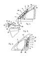
- in Seitenansicht und teilweise im Schnitt eine dritte Ausführungsform eines erfindungsgemäßen Außenrückblickspiegels,
- Fig. 5
- in Draufsicht und teilweise in explosiver Darstellung den Außenrückblickspiegel gemäß Fig. 4,
- Fig. 6 und Fig. 7
- in Darstellungen entsprechend den Fig. 4 und 5 eine vierte Ausführungsform eines erfindungsgemäßen Außenrückblickspiegels..
- Die im folgenden beschriebenen Außenrückblickspiegel sind für Kraftfahrzeuge vorgesehen und haben jeweils wenigstens eine Beleuchtung, die in unterschiedlicher Weise angeordnet und ausgebildet sein kann, um unterschiedliche Leuchtfunktionen zu erfüllen.
- Der Außenrückblickspiegel gemäß den Fig. 1 und 2 hat einen Spiegelkopf 1 und einen Spiegelfuß 2, mit dem der Außenrückblickspiegel am Kraftfahrzeug befestigt werden kann. In Fig. 1 ist beispielhaft ein Teil des Türbleches 3 des Kraftfahrzeuges dargestellt. Der Spiegelfuß 2 kann am Türblech 3 in bekannter Weise befestigt werden, beispielsweise durch Einrasten, Einhängen, Verschrauben oder durch andere bekannte Befestigungsmöglichkeiten. Der Spiegelkopf 1 ist gegenüber dem Spiegelfuß 2 abklappbar, vorzugsweise in Fahrtrichtung nach hinten und nach vorn. Der Außenrückblickspiegel nach den Fig. 1 und 2 ist als Einachsspiegel ausgebildet, bei dem der Spiegelkopf 1 beim Abklappen nach vorn und nach hinten jeweils um die gleiche aufrechte Achse schwenkt. Da solche Schwenkausbildungen bei Außenrückblickspiegeln bekannt sind, werden sie nicht näher erläutert.
- Der Spiegelfuß 2 weist an seiner dem Boden zugewandten Unterseite 4 einen Aufnahmeraum 5 auf, in dem eine Leuchtmitteleinheit 6 untergebracht wird. Zur Bildung des Aufnahmeraumes 5 ist die Unterseite 4 des Spiegelfußes entsprechend verformt (Fig. 2). Der Aufnahmeraum 5 liegt etwa in halber Breite des Spiegelfußes 2 und ist nach außen durch eine Rückwand 7 und in Fahrtrichtung nach vorn und hinten durch Seitenwände 8, 9 begrenzt.
- Nach oben wird der Aufnahmeraum 5 durch eine Decke 10 begrenzt, die in eine aufwärts gerichtete Anlagewand 11 des Spiegelfußes 2 übergeht (Fig. 1). Die Anlagewand 11 ist vorteilhaft mit einer Dichtung 12 belegt. Wie sich aus den Fig. 1 und 2 ergibt, sind in der Anlagewand 11, die im Ausführungsbeispiel etwa dreieckförmigen Umriß hat, drei Hülsen 13 bis 15 vorgesehen, die über die Anlagewand 11 vorstehen, die Dichtung 12 durchsetzen und in der Einbaulage in Öffnungen 16, 17 im Türblech 3 eingreifen. Die Hülsen 13 bis 15 wirken mit Gewindebolzen 18 zusammen, mit denen der Außenrückblickspiegel am Türblech 3 befestigt wird.
- Die Leuchtmitteleinheit 6 ist Bestandteil eines Anbauelementes 19, das in der Einbaulage des Außenrückblickspiegels zwischen dem Türblech 3 und dem Spiegelfuß 2 angeordnet ist. Das Anbauelement 19 hat ein Gehäuse 20, dessen Umrißform der Innenform des Aufnahmeraumes 5 des Spiegelfußes 2 angepaßt ist. Das Gehäuse 20 hat eine Rückwand 21, eine Vorderwand 22, (nicht dargestellte) Seitenwände sowie eine Oberwand 23. Mit diesen Wänden liegt das Gehäuse 20 in der Einbaulage an der Rückwand 7, den Seitenwänden 8, 9 und der Decke 10 des Aufnahmeraumes 5 an. Das Gehäuse 20 ist nach unten in Richtung auf den Boden durch eine Lichtscheibe 24 geschlossen, durch die das von Leuchtmitteln 25 im Gehäuse 20 ausgestrahlte Licht nach unten in Richtung auf den Boden fällt. Die im Gehäuse 20 untergebrachten Leuchtmittel 25 sind vorzugsweise LEDs, können aber auch Glühlampen oder andere, in der Kraftfahrzeugtechnik bekannte Leuchtmittel sein. Die Lichtscheibe 24 ist im Ausführungsbeispiel eben und liegt in der Einbaulage bündig zur Unterseite 4 des Spiegelfußes 2. Die Lichtscheibe 24 kann beispielsweise entsprechend der Designvorgabe auch dem Spiegelfuß 2 entsprechend gewölbt sein.
- An das Gehäuse 20 schließt aufwärts eine Rückwand 26 an, die in Verlängerung der Rückwand 21 des Gehäuses 20 liegt und in der Einbaulage an der Dichtung 12 flächig anliegt. Die Rückwand 26 hat Öffnungen 27 für den Durchtritt der Hülsen 13 bis 15 und für Kabel. Die Rückwand 26 ist etwa an die Umrißform der Dichtung 12 angepaßt. Von der Rückwand 26 stehen Rasthaken 28 ab, denen im Türblech 3 eine entsprechende (nicht dargestellte) Rastöffnung zugeordnet ist.
- Die Leuchtmitteleinheit 6 des Anbauelementes 19 bildet eine Umfeldbeleuchtung, die unabhängig vom Außenrückblickspiegel mittels der Rasthaken 28 am Türblech 3 des Kraftfahrzeuges befestigt werden kann. Es ist abweichend vom dargestellten Ausführungsbeispiel auch möglich, das Anbauelement 19 am Türblech 3 einzuhängen, zu verschrauben oder auf andere Weise zu befestigen. Es ist ferner möglich, das Anbauelement 19 am Spiegelfuß 2 zu befestigen. Da die Leuchtmitteleinheit 6 Teil des Anbauelementes 19 ist, muß die Leuchtmitteleinheit nicht in den Spiegelfuß 2 integriert werden.
- Im dargestellten Ausführungsbeispiel wird zunächst das Anbauelement 19 am Türblech 3 befestigt. Anschließend wird der Spiegelfuß 2 einschließlich Spiegelkopf 1 am Türblech 3 mit den Gewindebolzen 18 in bekannter Weise angeschraubt. Die Rückwand 26 des Anbauelementes 19 wird vom Spiegelfuß 2 überdeckt, während die Leuchtmitteleinheit 6 im Aufnahmeraum 5 des Spiegelfußes 2 untergebracht wird. Durch den Spiegelfuß 2 wird das Anbauelement 19 sicher gehalten. Mit dem von den Leuchtmitteln 25 nach unten abgestrahlten Licht wird der Bereich neben der Kraftfahrzeugtür beleuchtet, so daß dieser Bereich, wenn das Fahrzeug bei Dunkelheit bestiegen werden soll, optimal ausgeleuchtet wird.
- Das Anbauelement 19 ist bis auf die Lichtscheibe 24 einstückig ausgebildet und besteht vorteilhaft aus einem Kunststoff. An der Außenseite der Vorderwand 22 sowie auch an den (nicht dargestellten) Seitenwänden des Gehäuses 20 des Anbauelementes 19 ist eine Dichtung 29 vorgesehen, die ein Eindringen von Schmutz in den Aufnahmeraum 5 verhindert.
- Fig. 3 zeigt einen Außenrückblickspiegel in Zweiachs-Ausführung. Der Spiegelkopf 1 ist in und entgegen Fahrtrichtung des Kraftfahrzeuges um jeweils eine Achse 30, 31 schwenkbar. Die beiden Schwenkachsen liegen parallel zueinander und erstrecken sich wie die Schwenkachse des Außenrückblickspiegels nach den Fig. 1 und 2 aufwärts. Solche Zweiachsspiegel sind bekannt und werden darum auch nicht näher erläutert.
- Der Spiegelfuß 2 ist wie bei der vorigen Ausführungsform an seiner Unterseite mit dem Aufnahmeraum 5 versehen, der die Leuchtmitteleinheit 6 des Anbauelementes 19 aufnimmt. Im Unterschied zum vorigen Ausführungsbeispiel liegt der Aufnahmeraum 5 nicht mittig in der Unterseite 4, sondern ist in Fahrtrichtung nach hinten versetzt in der Unterseite 4 vorgesehen. Der Aufnahmeraum 5 ist im übrigen im wesentlichen gleich ausgebildet wie bei der vorigen Ausführungsform. Selbstverständlich kann der Aufnahmeraum 5 auch bei einem Zweiachsspiegel mittig in der Unterseite 4 des Spiegelfußes 2 vorgesehen sein.
- Die dem Türblech 3 zugewandte Seite der Anlagewand 11 des Spiegelfußes 2 wird mit der Dichtung 12 belegt, die als flache Dichtscheibe ausgebildet ist und an der Anlagewand 11 befestigt werden kann. Es ist aber auch möglich, die Dichtung 12 zwischen der Anlagewand 11 des Spiegelfußes 2 und der Rückwand 26 des Anbauelementes 19 einzuklemmen.
- Die Rückwand 26 ist einstückig mit dem Gehäuse 20 der Leuchtmitteleinheit 6 ausgebildet, in dem die Leuchtmittel 25 untergebracht sind. In der Einbaulage strahlen die Leuchtmittel 25 das Licht nach unten auf den Boden ab.
- Von der Rückwand 26 des Anbauelementes 19 stehen die Rasthaken 28 ab, mit denen das Anbauelement 19 am Türblech 3 verrastet werden kann.
- Auch bei diesem Ausführungsbeispiel ist das Anbauelement 19 ein formstabiles, aber teilweise elastisches Bauteil, das als eigenständige Baueinheit zwischen dem Spiegelfuß 2 und dem Türblech 3 angeordnet wird. Das Anbauelement 19 bildet entsprechend der vorigen Ausführungsform eine Art Adapterstück zwischen dem Spiegelfuß 2 und der Fahrzeugtür 3.
- Die Fig. 4 und 5 zeigen eine Ausführungsform, bei der das Anbauelement 19 ein separates Bauteil ist, das zwischen dem Spiegelfuß 2 und dem Türblech 3 eingebaut wird. Das Anbauelement 19 steht über seinen Umfang über den Spiegelfuß 2 vor (Fig. 4). Die Leuchtmitteleinheit 6 des Anbauelementes ist benachbart zu dem in Fahrtrichtung vorn liegenden, schräg aufwärts gerichteten Rand 32 des Spiegelfußes 2 angeordnet. Die Leuchtmitteleinheit 6 hat das Gehäuse 20, in dem die Leuchtmittel 25 untergebracht sind. Die Leuchtmittel 25 sind innerhalb des Gehäuses 20 benachbart zum Rand 32 des Spiegelfußes 2 angeordnet. Das Gehäuse 20 ist in Fahrtrichtung nach vorn durch die Lichtscheibe 24 geschlossen, die bündig in der Außenseite des Anbauelementes 19 liegt. Im Querschnitt (Fig. 5) ist die Lichtscheibe 24 konvex gekrümmt. Je nach Gestaltung des Anbauelementes 19 kann die Lichtscheibe 24 selbstverständlich auch jede andere geeignete Querschnittsform haben.
- Das Anbauelement 19 hat in Ansicht Dreieckform. Seine Ränder liegen etwa parallel zu den Rändern des Spiegelfußes 2. Das Anbauelement 19 kann vollständig aus weichem, gummiartigem Material bestehen. Selbstverständlich ist auch eine Ausführung dieses Anbauelementes 19 in einer Kombination aus weichem und hartem, formstabilen Kunststoff denkbar.
- Das von den Leuchtmitteln 25 ausgesandte Licht tritt durch die Lichtscheibe 24 in Fahrtrichtung nach vorn heraus. In dieser Ausgestaltung bildet die Leuchtmitteleinheit 6 eine Wiederholblinkleuchte.
- Das Gehäuse 20 ist einstückig mit der Rückwand 26 des Anbauelementes 19 ausgebildet. Sie liegt in der Einbaulage flächig an der Anlagewand 11 des Spiegelfußes 2 an. Er weist die über die Anlagewand 11 vorstehenden Hülsen 13, 14 auf, die durch die Öffnungen 16, 17 in der Rückwand 26 des Anbauelementes 19 ragen und die mit den Gewindebolzen 18 (Fig. 1) bei der Montage des Außenrückblickspiegels zusammenwirken.
- Durch eine geeignete Optikgestaltung der Lichtscheibe 24 bzw. der Leuchtmitteleinheit 6 können die Lichtstrahlen 33 der Leuchtmittel 25 so gelenkt werden, daß sie schräg nach unten zum Boden gerichtet sind. In diesem Falle bildet die Leuchtmitteleinheit 6 des Anbauelementes 19 keine Wiederholblinkleuchte, sondern eine Umfeldleuchte, die den Bodenbereich neben der Fahrzeugtür beleuchtet.
- Es ist auch möglich, nur einen Teil der Leuchtmittel 25 für die Umfeldleuchte heranzuziehen. Dann kann die Leuchtmitteleinheit 6 als Wiederholblinkleuchte und als Umfeldleuchte eingesetzt werden. In diesem Falle ist es vorteilhaft, die Leuchtmittel der Umfeldleuchte unabhängig von den Leuchtmitteln der Wiederholblinkleuchte betätigen zu können.
- Bei der Ausführungsform nach den Fig. 6 und 7 befindet sich die Leuchtmitteleinheit 6 des Anbauelementes 19 an dem in Fahrtrichtung hinten liegenden, aufwärts gerichteten Rand 34 des Spiegelfußes 2. Der Rand 34 ist mit dem als Vertiefung ausgebildeten Aufnahmeraum 5 versehen, in dem die Leuchtmitteleinheit 6 in der Einbaulage liegt. Das Gehäuse 20 der Leuchtmitteleinheit 6 liegt an den Wandungen des Aufnahmeraumes 5 flächig an. Die Lichtscheibe 24 liegt bündig in der Außenseite des Randes 34 des Spiegelfußes 2.
- Im Gehäuse 20 sind die Leuchtmittel 25 untergebracht, die ihr Licht im Unterschied zur vorigen Ausführungsform in Fahrtrichtung nach hinten abstrahlen. Die Leuchtmitteleinheit 6 kann auch in diesem Falle als Wiederholblinkleuchte eingesetzt werden. Durch eine entsprechende Optikgestaltung der Leuchtmitteleinheit 6 ist es möglich, die Lichtstrahlen 33 entgegen Fahrtrichtung des Kraftfahrzeuges nach unten zu lenken, so daß die Leuchtmitteleinheit 6 als Umfeldleuchte dient. Wie beim vorigen Ausführungsbeispiel können die Lichtstrahlen 33 beispielsweise durch Optiken auf der Rückseite der Lichtscheibe 24 und/oder durch im Gehäuse 20 untergebrachte Reflektoren in der gewünschten Richtung gelenkt werden. Es ist ferner möglich, nur einen Teil der Leuchtmittel 25 für die Umfeldbeleuchtung heranzuziehen, während der restliche Teil der Leuchtmittel 25 für die Wiederholblinkleuchte eingesetzt werden kann. Entsprechend dem vorigen Ausführungsbeispiel ist es in einem solchen Fall zweckmäßig, die für die Umfeldbeleuchtung vorgesehenen Leuchtmittel 25 unabhängig von den übrigen Leuchtmitteln ein- und auszuschalten.
- An das Gehäuse 20 schließt die Rückwand 26 an, die vorteilhaft einstückig mit dem Gehäuse ausgebildet ist und in der Einbaulage flächig an der Anlagewand 11 des Spiegelfußes 2 anliegt. Während bei der Ausführungsform nach den Fig. 4 und 5 das Gehäuse 20 an dem in Fahrtrichtung vorderen Rand der Rückwand 26 vorgesehen ist, befindet sich das Gehäuse 20 bei der Ausführungsform nach den Fig. 6 und 7 an dem in Fahrtrichtung des Fahrzeuges rückwärtigen Rand der Rückwand 26. An dem dem Gehäuse 20 gegenüberliegenden Rand ist die Rückwand 26 spitzwinklig abgewinkelt. Dieser abgewinkelte Rand 35 der Rückwand 26 berührt den in Fahrtrichtung vorderen, aufwärts gerichteten Rand 32 des Spiegelfußes 2.
- Bei sämtlichen Ausführungsformen ist die Leuchtmitteleinheit 6 Bestandteil des separaten Anbauelementes 19, das zwischen dem Spiegelfuß 2 und der Fahrzeugtür angeordnet wird. Das Anbauelement 19 mit der Leuchtmitteleinheit 6 ist vorteilhaft einstückig ausgebildet. Das Anbauelement 19 kann aus einem harten Werkstoff, vorzugsweise einem entsprechenden Kunststoff, bestehen. Es ist auch möglich, das Anbauelement 19 aus flexiblem Material herzustellen, so daß es gleichzeitig auch eine Dichtungsfunktion zwischen dem Außenrückblickspiegel bzw. dessen Spiegelfuß 2 und dem Türblech 3 erfüllen kann. Es ist ferner möglich, das Anbauelement 19 teilweise aus einem harten Werkstoff und teilweise aus einem flexiblen Material herzustellen. So ist es beispielsweise möglich, das Gehäuse 20 der Leuchtmitteleinheit 6 aus einem entsprechend festen Werkstoff herzustellen, während die Rückwand 26 aus flexiblem Material bestehen kann.
- Da das Anbauelement 19 ein vom Spiegelfuß getrenntes Bauteil ist, steht der Innenraum des Spiegelfußes 2 und insbesondere des Spiegelkopfes 1 für andere Einbauten zur Verfügung. So können in den Spiegelkopf 1 problemlos die Antriebe zur Spiegelglasverstellung und zur motorischen Verstellung des Spiegelkopfes 1, Heizelemente für das Spiegelglas, Sender von Garagentoröffnern, Lautsprecher, Antennen, GPS-Module und dergleichen eingebaut werden.
Claims (20)
- Außenrückblickspiegel für Fahrzeuge, vorzugsweise für Kraftfahrzeuge, mit einem Spiegelfuß (2) und einem Spiegelkopf (1) sowie wenigstens einer Leuchtmitteleinheit (6), die wenigstens ein Leuchtmittel (25) und ein Gehäuse (20) aufweist, in dem das Leuchtmittel (25) untergebracht ist und das in einem Aufnahmeraum des Spiegelfußes (2) liegt,
dadurch gekennzeichnet, daß der Aufnahmeraum (5) eine Vertiefung im Spiegelfuß (2) ist, in die das Gehäuse (20) ragt, und daß die Leuchtmitteleinheit (6) Teil eines von Außenrückblickspiegel körperlich getrennten Anbauelementes (19) ist, das eine Wand (26) aufweist, die zwischen dem Spiegelfuß (2) und der Karosserie (3) des Fahrzeuges liegt. - Außenrückblickspiegel nach Anspruch 1,
dadurch gekennzeichnet, daß das Gehäuse (20) und die Wand (26) des Anbauelementes (19) einstückig miteinander ausgebildet sind. - Außenrückblickspiegel nach Anspruch 1 oder 2,
dadurch gekennzeichnet, daß das Anbauelement (19) wenigstens einen Formschlußteil (28, 35) aufweist. - Außenrückblickspiegel nach Anspruch 3,
dadurch gekennzeichnet, daß der Formschlußteil (28) durch Rasthaken gebildet ist. - Außenrückblickspiegel nach Anspruch 4,
dadurch gekennzeichnet, daß der Formschlußteil (28) in die Karosserie (3) des Fahrzeuges einrastbar ist. - Außenrückblickspiegel nach einem der Ansprüche 3 bis 5,
dadurch gekennzeichnet, daß der Formschlußteil (28, 35) von der Wand (26) des Anbauelementes (19) quer absteht. - Außenrückblickspiegel nach Anspruch 3 oder 6,
dadurch gekennzeichnet, daß der Formschlußteil (35) ein abgewinkelter Teil der Wand (26) des Anbauelementes (19) ist. - Außenrückblickspiegel nach einem der Ansprüche 1 bis 7,
dadurch gekennzeichnet, daß der Aufnahmeraum (5) durch einen geformten Abschnitt des Spiegelfußes (2) gebildet ist. - Außenrückblickspiegel nach einem der Ansprüche 1 bis 8,
dadurch gekennzeichnet, daß der Aufnahmeraum (5) an der Unterseite (4) des Spiegelfußes (2) vorgesehen ist. - Außenrückblickspiegel nach einem der Ansprüche 1 bis 8,
dadurch gekennzeichnet, daß der Aufnahmeraum (5) am vorderen und/oder rückwärtigen, aufwärts gerichteten Rand (32, 34) des Spiegelfußes (2) vorgesehen ist. - Außenrückblickspiegel nach einem der Ansprüche 1 bis 10,
dadurch gekennzeichnet, daß das Gehäuse (20) der Leuchtmitteleinheit (6) an der Wandung des Aufnahmeraumes (5) anliegt. - Außenrückblickspiegel nach einem der Ansprüche 1 bis 11,
dadurch gekennzeichnet, daß das Gehäuse (20) durch eine Lichtscheibe (24) geschlossen ist. - Außenrückblickspiegel nach einem der Ansprüche 1 bis 12,
dadurch gekennzeichnet, daß die Leuchtmitteleinheit (6) als Umfeldleuchte vorgesehen ist. - Außenrückblickspiegel nach einem der Ansprüche 1 bis 12,
dadurch gekennzeichnet, daß die Leuchtmitteleinheit (6) als Wiederholblinkleuchte ausgebildet ist. - Außenrückblickspiegel nach einem der Ansprüche 1 bis 14,
dadurch gekennzeichnet, daß das Anbauelement (19) Durchtrittsöffnungen (16, 17) für Befestigungsteile (13 bis 15) des Spiegelfußes (2), gegebenenfalls auch für Kabel, aufweist. - Außenrückblickspiegel nach einem der Ansprüche 1 bis 15,
dadurch gekennzeichnet, daß das Anbauelement (19) formstabil ist. - Außenrückblickspiegel nach einem der Ansprüche 1 bis 15,
dadurch gekennzeichnet, daß das Anbauelement (19) teilweise formstabil ist. - Außenrückblickspiegel nach Anspruch 17,
dadurch gekennzeichnet, daß das Anbauelement (19) Dichtelemente aufweist. - Außenrückblickspiegel nach einem der Ansprüche 1 bis 18,
dadurch gekennzeichnet, daß der Außenrückblickspiegel ein Einachsspiegel ist. - Außenrückblickspiegel nach einem der Ansprüche 1 bis 18,
dadurch gekennzeichnet, daß der Außenrückblickspiegel ein Zweiachsspiegel ist.
Applications Claiming Priority (3)
| Application Number | Priority Date | Filing Date | Title |
|---|---|---|---|
| DE10308073 | 2003-02-26 | ||
| DE10308073A DE10308073A1 (de) | 2003-02-26 | 2003-02-26 | Außenrückblickspiegel für Fahrzeuge, vorzugsweise für Kraftfahrzeuge |
| PCT/DE2004/000328 WO2004076236A1 (de) | 2003-02-26 | 2004-02-21 | Aussenrückblickspiegel für kraftfahrzeuge |
Publications (2)
| Publication Number | Publication Date |
|---|---|
| EP1597112A1 EP1597112A1 (de) | 2005-11-23 |
| EP1597112B1 true EP1597112B1 (de) | 2007-06-20 |
Family
ID=32841871
Family Applications (1)
| Application Number | Title | Priority Date | Filing Date |
|---|---|---|---|
| EP04713455A Expired - Lifetime EP1597112B1 (de) | 2003-02-26 | 2004-02-21 | Aussenrückblickspiegel für kraftfahrzeuge |
Country Status (4)
| Country | Link |
|---|---|
| US (1) | US7226194B2 (de) |
| EP (1) | EP1597112B1 (de) |
| DE (3) | DE10308073A1 (de) |
| WO (1) | WO2004076236A1 (de) |
Families Citing this family (2)
| Publication number | Priority date | Publication date | Assignee | Title |
|---|---|---|---|---|
| DE10256197A1 (de) * | 2002-12-02 | 2004-06-09 | Schefenacker Vision Systems Germany Gmbh & Co. Kg | Außenrückblickspiegel für Fahrzeuge, insbesondere Kraftfahrzeuge |
| US20220080892A1 (en) * | 2020-09-15 | 2022-03-17 | Ford Global Technologies, Llc | Vehicle body mounted side view mirror assemblies with accessory mounting platforms |
Family Cites Families (7)
| Publication number | Priority date | Publication date | Assignee | Title |
|---|---|---|---|---|
| US5497306A (en) | 1993-02-01 | 1996-03-05 | Donnelly Corporation | Exterior vehicle security light |
| US6572250B1 (en) * | 1999-03-15 | 2003-06-03 | Britax Wingard Limited | Exterior mirror having an attachment member including an approach light |
| DE60044260D1 (de) * | 1999-10-21 | 2010-06-02 | Federal Mogul Corp | Seitenspiegeleinrichtung mit beleuchtung und signalleuchten für fahrzeuge |
| AU2001238087A1 (en) * | 2000-02-11 | 2001-08-20 | Britax Vision Systems (North America) Inc. | Exterior mirror |
| FR2821308B1 (fr) * | 2001-02-28 | 2003-08-15 | Ficomirrors France Sas | Retroviseur muni d'un dispositif clignotant ou repetiteur de clignotement |
| US6817742B2 (en) * | 2003-01-24 | 2004-11-16 | Rocky Lin | Vehicle rearview mirror assembly with color changing legs |
| US20060092651A1 (en) * | 2004-11-01 | 2006-05-04 | Wen Huang | Automobile auxiliary mirror |
-
2003
- 2003-02-26 DE DE10308073A patent/DE10308073A1/de not_active Withdrawn
-
2004
- 2004-02-21 US US10/547,029 patent/US7226194B2/en not_active Expired - Lifetime
- 2004-02-21 EP EP04713455A patent/EP1597112B1/de not_active Expired - Lifetime
- 2004-02-21 DE DE112004000804T patent/DE112004000804D2/de not_active Expired - Fee Related
- 2004-02-21 WO PCT/DE2004/000328 patent/WO2004076236A1/de active IP Right Grant
- 2004-02-21 DE DE502004004138T patent/DE502004004138D1/de not_active Expired - Lifetime
Also Published As
| Publication number | Publication date |
|---|---|
| DE10308073A1 (de) | 2004-09-09 |
| WO2004076236A1 (de) | 2004-09-10 |
| US7226194B2 (en) | 2007-06-05 |
| US20060146429A1 (en) | 2006-07-06 |
| EP1597112A1 (de) | 2005-11-23 |
| DE502004004138D1 (de) | 2007-08-02 |
| DE112004000804D2 (de) | 2006-01-19 |
Similar Documents
| Publication | Publication Date | Title |
|---|---|---|
| EP1598237B1 (de) | Aussenrückblickspiegel für Fahrzeuge, insbesondere Kraftfahrzeuge | |
| EP1914118B1 (de) | Aussenrückspiegel mit Leuchtmittel | |
| EP1120312B1 (de) | Aussenrückblickspiegel für Fahrzeuge, vorzugsweise für Kraftfahrzeuge | |
| DE19538770B4 (de) | Außenrückblickspiegel für Fahrzeuge, vorzugsweise für Kraftfahrzeuge | |
| EP1737701A1 (de) | Aussenrückblickspiegel für fahrzeuge, vorzugsweise kraftfahrzeuge | |
| WO2005113291A1 (de) | Aussenrückblickspiegel für fahrzeuge, insbesondere für kraftfahrzeuge | |
| DE10337617B4 (de) | Leuchtvorrichtung für Fahrzeuge | |
| DE19538771B4 (de) | Außenrückblickspiegel für Fahrzeuge, vorzugsweise für Kraftfahrzeuge | |
| EP1215081A2 (de) | Leuchte für Fahrzeuge, vorzugsweise für Kraftfahrzeuge | |
| DE102018214790A1 (de) | Beleuchtungsvorrichtung für ein Kraftfahrzeug | |
| EP1859995B1 (de) | Außenspiegel eines Fahrzeugs | |
| DE102019210283A1 (de) | Außenrückspiegelanordnung mit integrierter Batterieladeanzeigefunktion | |
| DE10337615B3 (de) | Leuchtvorrichtung für Fahrzeuge | |
| DE102007010747A1 (de) | Außenrückblickspiegel für Fahrzeuge, insbesondere Kraftfahrzeuge | |
| EP1597112B1 (de) | Aussenrückblickspiegel für kraftfahrzeuge | |
| EP1293380A2 (de) | Hochgesetzte Bremsleuchte für Fahrzeuge, insbesondere Kraftfahrzeuge | |
| DE102010034927A1 (de) | Vorrichtung zur Außenbeleuchtung eines Fahrzeugs und Verfahren zum Betreiben der Vorrichtung | |
| EP0879735A2 (de) | Leuchte, insbesondere Heckleuchte, für Fahrzeuge, vorzugsweise Kraftfahrzeuge | |
| DE102007006290A1 (de) | Dachmodul für Fahrzeuge, vorzugsweise für Kraftfahrzeuge | |
| DE102006032023B4 (de) | Vorrichtung zum Beleuchten eines Kraftfahrzeuges | |
| EP1304262A2 (de) | Innenleuchte für Fahrzeuge, vorzugsweise für Kraftfahrzeuge | |
| DE202006010701U1 (de) | Vorrichtung zum Beleuchten eines Kraftfahrzeuges | |
| DE102006007884B4 (de) | Leuchtenanordnung an einem Kraftfahrzeug-Außenspiegel | |
| EP1964720A1 (de) | Aussenrückblickspiegel für Fahrzeuge, vorzugsweise für Kraftfahrzeuge | |
| DE10390993B4 (de) | Aussenrückblickspiegel für Fahrzeuge, insbesondere für Kraftfahrzeuge |
Legal Events
| Date | Code | Title | Description |
|---|---|---|---|
| PUAI | Public reference made under article 153(3) epc to a published international application that has entered the european phase |
Free format text: ORIGINAL CODE: 0009012 |
|
| 17P | Request for examination filed |
Effective date: 20050803 |
|
| AK | Designated contracting states |
Kind code of ref document: A1 Designated state(s): AT BE BG CH CY CZ DE DK EE ES FI FR GB GR HU IE IT LI LU MC NL PT RO SE SI SK TR |
|
| AX | Request for extension of the european patent |
Extension state: AL LT LV MK |
|
| DAX | Request for extension of the european patent (deleted) | ||
| RBV | Designated contracting states (corrected) |
Designated state(s): DE FR GB IT |
|
| GRAP | Despatch of communication of intention to grant a patent |
Free format text: ORIGINAL CODE: EPIDOSNIGR1 |
|
| GRAS | Grant fee paid |
Free format text: ORIGINAL CODE: EPIDOSNIGR3 |
|
| GRAA | (expected) grant |
Free format text: ORIGINAL CODE: 0009210 |
|
| AK | Designated contracting states |
Kind code of ref document: B1 Designated state(s): DE FR GB IT |
|
| REG | Reference to a national code |
Ref country code: GB Ref legal event code: FG4D Free format text: NOT ENGLISH |
|
| RAP2 | Party data changed (patent owner data changed or rights of a patent transferred) |
Owner name: SCHEFENACKER PATENTS S.A.R.L. |
|
| REF | Corresponds to: |
Ref document number: 502004004138 Country of ref document: DE Date of ref document: 20070802 Kind code of ref document: P |
|
| GBT | Gb: translation of ep patent filed (gb section 77(6)(a)/1977) |
Effective date: 20071016 |
|
| ET | Fr: translation filed | ||
| PLBE | No opposition filed within time limit |
Free format text: ORIGINAL CODE: 0009261 |
|
| STAA | Information on the status of an ep patent application or granted ep patent |
Free format text: STATUS: NO OPPOSITION FILED WITHIN TIME LIMIT |
|
| PG25 | Lapsed in a contracting state [announced via postgrant information from national office to epo] |
Ref country code: IT Free format text: LAPSE BECAUSE OF FAILURE TO SUBMIT A TRANSLATION OF THE DESCRIPTION OR TO PAY THE FEE WITHIN THE PRESCRIBED TIME-LIMIT Effective date: 20070620 |
|
| 26N | No opposition filed |
Effective date: 20080325 |
|
| REG | Reference to a national code |
Ref country code: GB Ref legal event code: 732E |
|
| REG | Reference to a national code |
Ref country code: FR Ref legal event code: CD |
|
| REG | Reference to a national code |
Ref country code: FR Ref legal event code: CA Ref country code: FR Ref legal event code: CD |
|
| REG | Reference to a national code |
Ref country code: DE Ref legal event code: R082 Ref document number: 502004004138 Country of ref document: DE Representative=s name: RAUSCH, GABRIELE, DIPL.-PHYS. DR.RER.NAT., DE |
|
| REG | Reference to a national code |
Ref country code: FR Ref legal event code: PLFP Year of fee payment: 13 |
|
| REG | Reference to a national code |
Ref country code: FR Ref legal event code: PLFP Year of fee payment: 14 |
|
| REG | Reference to a national code |
Ref country code: FR Ref legal event code: PLFP Year of fee payment: 15 |
|
| REG | Reference to a national code |
Ref country code: DE Ref legal event code: R084 Ref document number: 502004004138 Country of ref document: DE |
|
| PGFP | Annual fee paid to national office [announced via postgrant information from national office to epo] |
Ref country code: FR Payment date: 20230220 Year of fee payment: 20 |
|
| PGFP | Annual fee paid to national office [announced via postgrant information from national office to epo] |
Ref country code: GB Payment date: 20230220 Year of fee payment: 20 Ref country code: DE Payment date: 20230216 Year of fee payment: 20 |
|
| P01 | Opt-out of the competence of the unified patent court (upc) registered |
Effective date: 20230616 |
|
| REG | Reference to a national code |
Ref country code: DE Ref legal event code: R071 Ref document number: 502004004138 Country of ref document: DE |
|
| REG | Reference to a national code |
Ref country code: GB Ref legal event code: PE20 Expiry date: 20240220 |