EP1118917A1 - Dispositif de servocommande - Google Patents
Dispositif de servocommande Download PDFInfo
- Publication number
- EP1118917A1 EP1118917A1 EP00118799A EP00118799A EP1118917A1 EP 1118917 A1 EP1118917 A1 EP 1118917A1 EP 00118799 A EP00118799 A EP 00118799A EP 00118799 A EP00118799 A EP 00118799A EP 1118917 A1 EP1118917 A1 EP 1118917A1
- Authority
- EP
- European Patent Office
- Prior art keywords
- servo
- control
- load
- control circuit
- error
- Prior art date
- Legal status (The legal status is an assumption and is not a legal conclusion. Google has not performed a legal analysis and makes no representation as to the accuracy of the status listed.)
- Granted
Links
Images


Classifications
-
- G—PHYSICS
- G05—CONTROLLING; REGULATING
- G05B—CONTROL OR REGULATING SYSTEMS IN GENERAL; FUNCTIONAL ELEMENTS OF SUCH SYSTEMS; MONITORING OR TESTING ARRANGEMENTS FOR SUCH SYSTEMS OR ELEMENTS
- G05B9/00—Safety arrangements
- G05B9/02—Safety arrangements electric
- G05B9/03—Safety arrangements electric with multiple-channel loop, i.e. redundant control systems
-
- B—PERFORMING OPERATIONS; TRANSPORTING
- B30—PRESSES
- B30B—PRESSES IN GENERAL
- B30B15/00—Details of, or accessories for, presses; Auxiliary measures in connection with pressing
- B30B15/14—Control arrangements for mechanically-driven presses
- B30B15/148—Electrical control arrangements
Definitions
- the present invention relates to a servo control apparatus for driving a load, in particular a servo control apparatus that can control the load so that it follows the reference control value even if an abnormality occurs.
- a servo control apparatus that drives the transfer mechanism of a press machine, for instance, as the load, even if an abnormality takes place in a component device (servo controller, servo amplifier, servo motor, feedback detector, etc.) of the servo control apparatus, the transfer mechanism must operate in synchronism with the dies until the dies stop; otherwise the dies and the transfer mechanism may collide with each other. Therefore, it is mandatory for the servo control apparatus to continue to control the load even when a component device of the servo control apparatus fails.
- a component device servo controller, servo amplifier, servo motor, feedback detector, etc.
- One of the technologies known in the prior art to be capable of continuing the servo control of the load even when the servo control apparatus fails is a torque master-slave system that is configured with two sets of servo amplifiers and servo motors to drive the load.
- This apparatus is provided with one master servo control circuit 2, composed of a servo controller 3 that computes the torque command signal so that a load (not illustrated) follows the reference control signal determined by a reference control adjuster 1, a servo amplifier 4 that controls the electric power supplied to a servo motor according to the torque command signal provided by the servo controller 3, the servo motor 5 for driving the load supplied with electric power from the servo amplifier 4, a feedback detector 6 to detect a feedback value from the servo motor 5, an abnormality detector 7 that detects abnormalities in the servo controller 3, servo amplifier 4, servo motor 5 and feedback detector 6 and sends command signals to the reference control adjuster 1 and servo amplifier 4.
- a master servo control circuit 2 composed of a servo controller 3 that computes the torque command signal so that a load (not illustrated) follows the reference control signal determined by a reference control adjuster 1, a servo amplifier 4 that controls the electric power supplied to a servo motor according to the torque command signal provided by the
- the servo controller 3 outputs a torque command signal according to the reference control signal sent from the reference control adjuster 1 and the feedback signal from the feedback detector 6, and the calculated torque command signal is input into the servo amplifier 4.
- the servo amplifier 4 provides an electrical output to the servo motor 5 so that the servo motor 5 produces the torque required by the torque command signal.
- this apparatus is provided with a slave servo control circuit 8 configured with a servo amplifier 9 with the same configuration and functions as the above-mentioned one, a servo motor 10, and an error detector 11 that detects abnormalities in both the servo amplifier 9 and servo motor 10 and sends a command signal to the reference control adjuster 1 and the servo amplifier 9.
- this apparatus is configured additionally with a shaft 12 that is driven by servo motors 5 and 10 so that they are mechanically interlocked with each other and drive the load, and a power transmission mechanism 13 for transmitting the rotation of the shaft 12 to the load to drive the load.
- This apparatus is an AC servo motor drive control circuit 14 wherein AC current is converted to DC current by a single-phase rectifier circuit 16 in a converter unit 15, and a 3-phase AC servo motor 17 is driven and controlled using the DC current.
- the apparatus is provided also with relays 19, 20 that when a failure occurs, connect two of the three-phase power lines of the AC servo motor 17 to the smoothing capacitor 18, a component device in the converter unit 15. Because these relays 19, 20 connect the AC servo motor 17 to the smoothing capacitor 18, electrostatic energy stored in the smoothing capacitor 18 is supplied to the AC servo motor 17, and produces a stationary magnetic field, thereby stopping the AC servo motor 17.
- both servo amplifiers 4, 9 receive torque command signals from one servo controller 3. Consequently, if an abnormality occurs in the servo controller 3 or the feedback detector 6, both servo amplifiers 4, 9 cannot receive a torque command signal, so in this case, both servo motors 5, 10 go into a free running state.
- the load when either the servo controller 3 or the feedback detector 6 fails while the load is being operated, the load must be stopped by either (1) waiting for it to stop naturally due to friction, (2) using the braking force produced by a mechanical brake, or (3) using a dynamic braking system in which the armature of either servo motor 5 or 10 is short circuited.
- Method (1) there is the problem that the load continues to run for a long time because the friction force acting on the load driven by the servo motor is normally small.
- Method (2) has the problem that the distance that the load overruns becomes large since there is a considerable time delay before the mechanical brake is actuated.
- the dynamic brake is turned ON and OFF by mechanically activated contacts, and the time delay before the dynamic brake is operated is so large that the load overruns, and there is the problem that an AC motors cannot be used for servo motors 5 and 10 and only DC motors can be used.
- Another problem that exists with any of the above (1), (2) and (3) is that after the load enters the free running state, the position and speed of the load can no longer be controlled.
- the load can be prevented from overrunning, but there is the problem that the position and speed of the load cannot be controlled.
- there is another problem because only one AC servo motor 17 is used, so if the AC servo motor 17 fails, the servo-control function is lost.
- An object of the present invention is to provide a servo control apparatus that can continue to control the load so that it follows the reference control value even if an abnormality occurs in any portion of a servo controller, servo amplifier, servo motor, or feedback detector.
- the present invention provides a plurality of servo control circuits each of which can singly control a load; each servo control circuit is configured with a servo controller that computes command signals so that the load can follow a reference control value adjusted by a reference control adjuster, a servo amplifier for controlling the electric power supplied to a servo motor according to a command signal from the above-mentioned servo controller, the servo motor that is supplied with electric power from the servo amplifier and drives the load, and a feedback detector that detects the operating condition of the servo motor and feeds the detected condition back to the servo controller; the servo motor in each of the aforementioned servo control circuits is interlocked mechanically with each of the others so as to be capable of driving the one load through a drive transmission mechanism, and if an abnormality takes place in any of the above-mentioned plurality of servo control circuits, the other servo control circuits, which are still normal, can continue to
- each servo control circuit cooperates with each of the others to control the load so as to follow the reference control signal.
- the reference control adjuster is made to generate a reference control signal that stops the load when an abnormality occurs in any of the servo control circuits, the other servo control circuits, which are still normal, continue to control the load so that the load is stopped as it follows the reference control signal.
- a slave servo amplifier is given a command signal from the master servo controller during normal operation, at a location upstream of the servo amplifier in the above-mentioned slave servo control circuit; and a command signal selector is provided and can switch to the command signal input from the slave servo controller when an abnormality occurs in the master servo control circuit; thereby the load can be controlled in master-slave fashion to follow the reference control signal by both the master and slave servo motors when no abnormality appears in any of the servo control circuits on the master or slave sides.
- Fig. 1 is a diagram showing an example of conventional servo control apparatus.
- Fig. 2 is a schematic diagram of another example of conventional servo control apparatus.
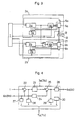
- Fig. 3 is a diagram showing the first embodiment of the servo control apparatus according to the present invention.
- Fig. 4 is an enlarged diagram showing details of an example of a servo controller used in the servo control apparatus in Fig. 3.
- Fig. 5 is a schematic diagram of the second embodiment of the servo control apparatus according to the present invention.
- Figs. 3 and 4 are diagrams generally showing the first embodiment of the servo control apparatus according to the present invention.
- the servo control apparatus of the present invention is provided with two sets of servo control circuits configured with servo controllers 3a, 3b, servo amplifiers 4a, 4b, servo motors 5a, 5b, feedback detectors 6a, 6b and abnormality detectors 7a, 7b which are disposed and arranged in.the same way as in the master servo control circuit 2, shown in Fig. 1.
- both servo motors 5a and 5b control the load so as to follow a reference control value set by a reference control adjuster 1.
- a torque command selector 21 is provided at a location upstream of the servo amplifier 4b in the slave servo control circuit 2b, and selects and switches the torque command signal according to a signal sent from an abnormality detector 7a in the master servo control circuit 2a.
- a torque command value calculated by the master servo controller 3a is input into the master servo amplifier 4a, and a torque command value is input to the slave servo amplifier 4b from either the master or slave servo controller 3a or 3b, as selected by the torque command selector 21.
- the reference control adjuster 1 produces reference control signals to be followed by the load, for instance, reference position values or reference speed values, continuously and sends them to servo controllers 3a and 3b as commands.
- Feedback detectors 6a and 6b can detect the angular position, speed, etc. of the shaft 12 using a rotary encoder, resolver, pulse generator, etc.
- the drive transmission mechanism 13 can be configured with gears, rack and pinion drive, chain, timing belt, etc.
- Each servo controller 3a or 3b computes a torque command value to be sent to servo amplifiers 4a, 4b according to the reference control signal from the reference control adjuster 1 and a feedback signal from the respective feedback detectors 6a, 6b.
- the method of calculating the torque command value based on the reference control value and the feedback value is, for example, a PID control or two degrees of freedom PID control method when the reference control and feedback values are speeds. If the reference control and feedback values are positions, a reference speed value is calculated by the PID control or two degrees of freedom PID control method, and a torque command value can be calculated which is proportional to the difference between the reference speed value and the speed feedback value obtained by differentiating the position feedback value with respect to time in servo controllers 3a, 3b, for instance.
- Fig. 4 is a more detailed view showing an example of the servo controller 3a.
- the servo controller 3a has a position reference control value and a position feedback value as its inputs; based on the reference control value and the feedback value, a reference speed value is calculated by a PID control method, and a torque command value is computed that is proportional to the difference between the reference speed value and the speed feedback value obtained by differentiating the position feedback value with respect to time in the servo controller 3a, as typically shown in Fig. 4.
- the servo controller 3a is provided with a subtractor 22 that calculates the difference in positions between the reference control value entered from the reference control adjuster 1 and position feedback value input from the feedback detector 6a, a PID controller 23 for computing the reference speed value by a PID computation method using the position difference calculated by and input from the subtractor 22, a differentiator 24 that calculates a speed feedback value by differentiating the position feedback value with respect to time, a subtractor 25 for calculating the difference between the reference speed value obtained from the PID controller 23 and the speed feedback value obtained from the differentiator 24, i.e. the speed difference, and a multiplier 26 that computes the torque command value to be sent to the servo amplifier 4a by multiplying the speed difference calculated in the subtractor 25 by a gain setting.
- This servo controller 3a is provided with a feedback signal checker 27 that checks the feedback signal to see if there is any abnormality, for example, if the voltage of the feedback signal is excessively low or the result of a parity check is not normal, and decides that an error has occurred and generates an error signal, a first excess value checker 28 that decides an error has occurred if the position difference calculated by the subtractor 22 is excessive and generates an error signal, a second excess value checker 29 that judges an error has occurred if the speed difference computed by the subtractor 25 is abnormally high and generates an error signal, and a watchdog timer 30 that monitors the operation of an arithmetic circuit in the servo controller 3a and decides an error has occurred if the timer times out and generates an error signal.
- a feedback signal checker 27 that checks the feedback signal to see if there is any abnormality, for example, if the voltage of the feedback signal is excessively low or the result of a parity check is not normal, and decides that an
- the error signals produced by the feedback signal checker 27, excess value checkers 28, 29 and watchdog timer 30 are all sent to the error detector 7a.
- the servo controller 3b is configured in the same way as the above-mentioned servo controller 3a.
- Each servo amplifier 4a or 4b controls the supply of electric power to the respective servo motors 5a or 5b so they are capable of producing the torque required by the torque command signal, and thus controlled power is supplied to corresponding servo motor 5a or 5b.
- power is controlled by the pulse width modulation (PWM) control method, wherein an IGBT or power transistor is turned ON and OFF according to a vector control principle, for instance.
- PWM pulse width modulation
- Each servo motor 5a or 5b generates the torque required by the torque command signal using power supplied from the respective servo amplifiers 4a or 4b, rotates a shaft 12, thereby driving a load through a drive transmission mechanism 13 to follow the reference control value.
- Error detectors 7a and 7d in the master and slave servo control circuits 2a and 2b detect errors in the corresponding servo controllers 3a or 3b, servo amplifiers 4a or 4b, servo motors 5a or 5b, and feedback detectors 6a and 6b. Any of the following detection methods are used in practice.
- an error in the arithmetic circuit is detected by time-out of the watchdog timer 30, (2) a control error is detected by observing an excessive difference between the reference control value and the feedback value, and (3) an error in the feedback values is detected by an excessively low voltage signal from the feedback detector 6a or 6b, or a parity error.
- methods for detecting an error in the servo amplifier 4a or 4b include, for instance, (1) a method of detecting an error in the arithmetic circuit by time-out of a watchdog timer not illustrated, (2) another method of detecting an error in a control process or circuit by detecting an excessive electric current, flowing in any power control element (not illustrated), and another method for detecting an error in a control process or circuit by measuring the temperature of any power control element (not illustrated) and detecting an over-temperature.
- an error in the servo motors 5a or 5b can be detected by, for instance, measuring the temperature of the motor unit (not illustrated) using a temperature sensor embedded in the unit, and detecting an excessive temperature rise, thus an error in a control process or circuit can be detected.
- the encoder measures the amount of light, and if the amount is insufficient, it is decided that an error has occurred, for example.
- the torque command value selector 21 When there is no abnormality, the torque command value selector 21 is switched so that the torque command value is input into the slave servo amplifier 4b, from the master servo controller 3a. Only when an error occurs in the master servo control circuit 2a, the torque command value is input into the servo amplifier 4b from the slave servo controller 3b. Therefore, when there is no abnormality in any of the master and slave servo control circuits 2a and 2b, the master servo controller 3a inputs a torque command value into the master servo amplifier 4a and into the slave servo amplifier 4b via the torque command value selector 21. Thereby, both the master and slave servo motors 5a and 5b operate in the master-slave torque control mode to make the load follow the reference control value. At this time, the torque command value computed in the slave servo controller 3b is not used.
- the master servo amplifier 4a If the error detector 7a detects an abnormality in the servo controller 3a, servo amplifier 4a, servo motor 5a or feedback detector 6a in the master servo control circuit 2a, the master servo amplifier 4a is stopped from supplying power to the servo motor 5a by a signal sent from the error detector 7a, and the servo motor 5a is allowed to run freely.
- the torque command value selector 21 is switched by a signal transmitted from the above-mentioned error detector 7a, so that torque command signals are input from the slave servo controller 3b into the slave servo amplifier 4b, therefore a control loop composed of the servo controller 3b, servo amplifier 4b, servo motor 5b and feedback detector 6b in the slave servo control circuit 2b continues to control the load so as to follow the reference control value.
- the slave servo controller 3b has been computing torque command values before the torque command value selector 21 was switched, parameters depending on past control information, for example, outputs from an integrating unit, are continuously preserved, therefore, torque command values to the servo amplifier 4b are smoothly transferred when the torque command value selector 21 is switched.
- the slave servo amplifier 4b stops supplying power to the servo motor 5b, and the servo motor 5b is allowed to run freely.
- the load is continuously controlled to follow the reference control value by the other control loop comprised of the servo controller 3a, servo amplifier 4a, servo motor 5a and feedback detector 6a in the master servo control circuit 2a.
- the reference control adjuster 1 when the reference control adjuster 1 is adjusted to generate a reference control value to stop the load if an error is detected by the error detector 7a or 7b in either the master or slave servo control circuit 2a or 2b described above, the normal servo control circuit 2a or 2b of either the master or slave control circuits can continue normal control operations, therefore, the load can be stopped by following the reference control value.
- the signal controlling the gate of an IGBT or power transistor is turned OFF, or a contactor is opened, and so on.
- the load can be controlled continuously and can follow the reference control value even if an abnormality occurs in any portion of the servo controllers 3a, 3b, servo amplifiers 4a, 4b, servo motors 5a, 5b and feedback detectors 6a, 6b, that is, in any component element.
- the load can be stopped by a controlled braking force produced electrically by servo motors 5a, 5b following the reference control value, thus the load can be prevented from running away.
- the transfer mechanism can be operated in synchronism with the dies until the dies stop even if any abnormality occurs in the servo control apparatus, so a collision between the dies and the transfer mechanism can be avoided. Also when the range of movement of a load is small as in the case of the transfer mechanism of a press machine, the transfer mechanism can be prevented from overrunning when an abnormality occurs, thus the press machine can be protected from damage and the availability of the press machine can be increased.
- the electrical circuit one of the component devices of the present apparatus can be constituted without requiring parts subject to yearly deterioration, such as relay contacts, consequently, the circuit can be operated stably for a long time.
- Fig. 5 is a schematic diagram showing the second embodiment of the present invention.
- This servo control apparatus is composed of a master servo control circuit 2a, configured in the same way as those shown in Figs. 3 and 4, and three sets of servo control circuits 2b, 2c, 2d with the same configuration as the slave servo control circuit shown in Figs. 3 and 4; servo motors 5a, 5b, 5c, 5d in these four sets of servo control circuits 2a, 2b, 2c, 2d are interlocked mechanically to drive a load, not illustrated, so as to follow a reference control value set by a reference control adjuster 1.
- Each torque command value selector 21 provided in each of the aforementioned slave servo control circuit 2b, 2c, or 2d is configured as follows.
- the torque command value selector 21 in the servo control circuit 2b selects the torque command value from the servo controller 3a when the error detector 7a does not detect an abnormality in the servo control circuit 2a, or another torque command value from the servo controller 3b when the error detector 7a detects an abnormality in the servo control circuit 2a, and outputs either command value to the servo amplifier 4b.
- the torque command value selector 21 provided in the servo control circuit 2c selects a torque command value from the servo controller 3a when the error detector 7a does not detect an abnormality in the servo control circuit 2a, and another torque command value from the servo controller 3b when the error detector 7a detects an abnormality in the servo control circuit 2a and the error detector 7b does not detect any abnormality in the servo control circuit 2b, and selects another torque command value from the servo controller 3c when the error detector 7a detects an abnormality in the servo control circuit 2a and the error detector 7b detects an error in the servo control circuit 2b, and sends one of these torque command values to the servo amplifier 4c.
- the torque command value selector 21 provided in the servo control circuit 2d selects a torque command value from the servo controller 3a when the error detector 7a does not detect any error in the servo control circuit 2a, or another torque command value from the servo controller 3b when the error detector 7a detects an error in the servo control circuit 2a and the error detector 7b does not detect an abnormality in the servo control circuit 2b, or another torque command value from the servo controller 3c when the error detector 7a detects an error in the servo control circuit 2a, the error detector 7b detects an abnormality in the servo control circuit 2b and the error detector 7c does not detect an error in the servo control circuit 2c, or another torque command value from the servo controller 3d when the error detector 7a detects an error in the servo control circuit 2a, the error detector 7b detects an abnormality in the servo control circuit 2b and the error detector 7c detects an error in the servo control circuit 2c, and output
- Item number 31 refers to a shaft both ends of which are connected to the shafts of the slave servo motors 5c and 5d
- item number 32 is a drive transmission device that mechanically links shafts 12 and 31 and drives a load that is not illustrated.
- This drive transmission mechanism 32 is composed of gears, rack and pinions, chains, timing belts, etc. although not illustrated.
- Figs. 3 and 5 are identified with the same item numbers, and each component element in the slave servo control circuits 2c and 2d in Fig. 5 is identified with a suffix c or d to discriminate it from those in Fig. 3.
- a torque command value from the servo controller 3c is output to servo amplifiers 4c and 4d.
- the servo control circuit 2c becomes the master, and the servo control circuit 2d functions as the slave, while the load continues to be controlled in the master-slave torque mode, wherein the load is controlled so as to follow the reference control signal from the reference control adjuster 1.
- the error detector 7a detects an abnormality in the servo control circuit 2a and the error detector 7c senses an error in the servo control circuit 2c, for example, the torque command value from the servo controller 3b in the servo control circuit 2b is output to servo amplifiers 4b and 4d.
- the servo control circuit 2b works as the master, and the servo control circuit 2d as the slave, so the master-slave torque control configuration continues to control the load to follow the reference control value from the reference control adjuster 1.
- the error detector 7a detects an abnormality in the servo control circuit 2a and the error detector 7b detects an error in the servo control circuit 2b and the error detector 7c detects an error in the servo control circuit 2c, for instance, the torque command signal from the servo controller 3d in the servo control circuit 2d is output to the servo amplifier 4d. That is, the one normal servo control circuit 2d continues to control the load so as to follow the reference control signal from the reference control adjuster 1.
- Fig. 3 shows a system wherein two servo motors 5a and 5b are interlocked with each other by driving opposite ends of one shaft 12, methods of interlocking through gears or a timing belt can also be used. Also when the error detector 7a detects an abnormality in the master servo control circuit 2a, the control gain of the slave servo controller 3b can be adjusted, or when an error in the slave servo control circuit 2b is sensed by the error detector 7b, the control gain of the master servo controller 3a may also be changed.
- the reference control adjuster 1 can produce a reference control value with a smaller maximum acceleration than that for normal operation. In this case, either one of the servo motors 5a and 5b can provide sufficient torque to follow the reference control value when an error occurs, therefore even if the available torque is insufficient to make the load follow the reference control value for normal operation, the servo control apparatus according to the present invention can be applied.
- the type of reference control value to be produced by the reference control adjuster 1 and the methods by which the servo controllers 3a, 3b compute torque command values can be changed when the error detector 7a or 7b detects an error in the master or slave servo control circuit 2a or 2b, respectively.
- the reference control adjuster 1 provides a reference position and servo controllers 3a, 3b performing a position feedback control operation, and when the error detector 7a or 7b detects an error, the reference control adjuster 1 can be changed to provide a reference speed value while the servo controllers 3a, 3b are changed to speed feedback control.
- error detectors 7a, 7b it is also possible to configure part or all of error detectors 7a, 7b to be contained within servo controllers 3a, 3b or servo amplifiers 4a, 4b or distributed between the controllers and the amplifiers.
- error detectors 7a, 7b for servo controllers 3a, 3b, servo amplifiers 4a, 4b, servo motors 5a, 5b and feedback detectors 6a, 6b are housed as one set inside servo controllers 3b, 3a or another set in servo amplifiers 4b, 4a.
- servo controller 3a and the servo amplifier 4a are integrated into one body and the servo controller 3b and the servo amplifier 4b are combined together, or one in which a reference control adjuster is built into each of servo controllers 3a, 3b to produce a reference control value, or one in which a speed command instead of a torque command is sent from the servo controller to the servo amplifier to input a speed command value into servo amplifiers 4a, 4b.
- Fig. 3 shows a case in which two servo motors 5a and 5b operate in a torque master-slave system when no error occurs
- the torque command value selector 21 can be omitted, that is, the system configuration can be modified so that the servo amplifier 4a always receives torque command values from the servo controller 3a, while the servo amplifier 4b receives torque command values at all times from the servo controller 3b.
- Other modifications and adjustments can of course be effected as long as the claims of the present invention are not exceeded.
- a servo control circuit is composed of a servo controller that computes torque command signal so that a load can follow a reference control value set by the reference control adjuster, a servo amplifier for controlling the electric power supplied to the servo motor according to a command signal sent from the above-mentioned servo controller, a servo motor that drives the load using power supplied from the servo amplifier, and a feedback detector for detecting the operating status of the servo motor and feeding back the status to the servo controller, thereby a single servo control circuit can control the load; a plurality of servo control circuits are provided, and the servo motor in each of the aforementioned servo control circuits is mechanically interlocked with other servo motors in other servo control circuits so that one load can be driven through a drive transmission mechanism.
- the above-mentioned configuration can continue to control the load even when an abnormality occurs in any of the above
- the load can be continuously controlled and follow the reference control value. If an abnormality arises, the load can be stopped by a controlled braking force produced electrically in the servo motor following the reference control value, consequently the load can be prevented from running away.
- the transfer mechanism can be operated in synchronism with the dies until the dies stop, so the transfer mechanism can be prevented from colliding with the dies.
- the transfer machine can be prevented from overrunning if an error occurs, therefore the press machine can be protected from damage, resulting in an increase in the operating availability of the press machine.
- the electrical circuit constituting this apparatus does not include any components that can deteriorate with time, such as relay contacts, consequently, the apparatus has the preferred advantage that it can operate stably for a long time.
- one of a plurality of servo control circuits is made the master servo control circuit, and the others are defined as slave servo control circuits, and at a location upstream of the servo amplifier in the above-mentioned slave servo control circuits, a slave servo amplifier is arranged to receive command inputs normally from the master servo controller, and a command value selector is provided and is capable of switching to the slave servo controller to input command values if the master servo control circuit fails unexpectedly, thereby the load can be controlled in the master-slave mode to follow the reference control value using both the master and slave servo motors as long as no abnormality arises in either the master or slave servo control circuits.
- This performance is a preferable advantage.
Applications Claiming Priority (2)
| Application Number | Priority Date | Filing Date | Title |
|---|---|---|---|
| JP2000012972A JP4096481B2 (ja) | 2000-01-21 | 2000-01-21 | サーボ制御装置 |
| JP2000012972 | 2000-01-21 |
Publications (2)
| Publication Number | Publication Date |
|---|---|
| EP1118917A1 true EP1118917A1 (fr) | 2001-07-25 |
| EP1118917B1 EP1118917B1 (fr) | 2004-02-25 |
Family
ID=18540629
Family Applications (1)
| Application Number | Title | Priority Date | Filing Date |
|---|---|---|---|
| EP00118799A Expired - Lifetime EP1118917B1 (fr) | 2000-01-21 | 2000-08-30 | Dispositif de servocommande |
Country Status (4)
| Country | Link |
|---|---|
| US (1) | US6384561B1 (fr) |
| EP (1) | EP1118917B1 (fr) |
| JP (1) | JP4096481B2 (fr) |
| DE (1) | DE60008493T2 (fr) |
Cited By (5)
| Publication number | Priority date | Publication date | Assignee | Title |
|---|---|---|---|---|
| CN102939231A (zh) * | 2010-04-12 | 2013-02-20 | 雷诺股份公司 | 在其选择按钮发生故障时管理发动机扭矩分配设备的方法 |
| CN103123478A (zh) * | 2010-01-12 | 2013-05-29 | 株式会社安川电机 | 同步控制装置 |
| RU2565598C1 (ru) * | 2014-08-20 | 2015-10-20 | Федеральное государственное бюджетное образовательное учреждение высшего профессионального образования "Южно-Уральский государственный университет" (национальный исследовательский университет) (ФГБОУ ВПО "ЮУрГУ" (НИУ)) | Система управления группой электроприводов с параллельными каналами регулирования |
| WO2018158039A1 (fr) * | 2017-02-28 | 2018-09-07 | Siemens Aktiengesellschaft | Commutation entre contrôleurs d'éléments pendant le fonctionnement d'une voie de chemin de fer |
| WO2018158038A1 (fr) * | 2017-02-28 | 2018-09-07 | Siemens Aktiengesellschaft | Commutation entre contrôleurs d'éléments pendant le fonctionnement d'une voie de chemin de fer |
Families Citing this family (25)
| Publication number | Priority date | Publication date | Assignee | Title |
|---|---|---|---|---|
| US6825634B2 (en) * | 2001-01-18 | 2004-11-30 | Lockeed Martin Corporation | System and method for a scalable motion controller for controlling a plurality of servo motors |
| JP2002354825A (ja) * | 2001-05-22 | 2002-12-06 | Toshiba Corp | 電力変換装置 |
| US7002315B2 (en) * | 2002-05-28 | 2006-02-21 | Toshiba Kikai Kabushiki Kaisha | Servo control device |
| JP3923047B2 (ja) * | 2003-03-04 | 2007-05-30 | ファナック株式会社 | 同期制御装置 |
| JP2005219133A (ja) * | 2004-02-03 | 2005-08-18 | Fanuc Ltd | ロボット用サーボモータ制御装置およびロボット |
| DE102004009256B4 (de) * | 2004-02-26 | 2008-04-03 | Schuler Pressen Gmbh & Co. Kg | Mechanische Mehrservopresse |
| US7429836B2 (en) * | 2004-06-03 | 2008-09-30 | Canon Kabushiki Kaisha | Motor driver circuit, control method thereof, and electronic apparatus |
| JP2006076699A (ja) * | 2004-09-08 | 2006-03-23 | Daifuku Co Ltd | 物品搬送車 |
| EP1672769A3 (fr) * | 2004-12-18 | 2009-07-08 | LuK Lamellen und Kupplungsbau Beteiligungs KG | Dispositif de commande pour éléments de véhicule |
| ITMI20060193A1 (it) * | 2006-02-03 | 2007-08-04 | Savio Macchine Tessili Spa | Sistema di azionamento peer filatoi open-end ad elevata produzione |
| JP4699247B2 (ja) * | 2006-03-15 | 2011-06-08 | 株式会社マキタ | モータの速度制御装置 |
| KR101583208B1 (ko) * | 2007-11-09 | 2016-01-12 | 밤코 인터내셔널, 인크. | 구동 장치 및 프레스 머신에 대한 방법 |
| JP2011217530A (ja) * | 2010-03-31 | 2011-10-27 | Toshiba Mach Co Ltd | サーボ制御方法及びサーボ制御装置 |
| WO2011142015A1 (fr) * | 2010-05-12 | 2011-11-17 | トヨタ自動車株式会社 | Dispositif et procédé d'évaluation de l'anomalie d'un opérateur |
| JP5459199B2 (ja) * | 2010-12-21 | 2014-04-02 | ブラザー工業株式会社 | 画像形成装置 |
| JP5949926B2 (ja) * | 2012-08-30 | 2016-07-13 | トヨタ自動車株式会社 | 倒立型移動体及びその制御方法 |
| CN103064408B (zh) * | 2012-12-21 | 2015-09-16 | 兰州飞行控制有限责任公司 | 一种飞机舵机伺服系统故障检测方法 |
| JP5983457B2 (ja) * | 2013-02-19 | 2016-08-31 | トヨタ自動車株式会社 | 倒立二輪車及びその制御方法 |
| MX369130B (es) * | 2013-03-12 | 2019-10-30 | Vamco Int Inc | Máquina de prensa. |
| US10357895B2 (en) * | 2015-04-16 | 2019-07-23 | Bohnert Equipment Company, Inc. | Barrel hoop driving apparatus and electric drive |
| CN106325218B (zh) * | 2016-08-18 | 2019-03-01 | 深圳市优必选科技有限公司 | 一种伺服器、伺服器控制系统及其通信方法 |
| CN106696342B (zh) * | 2017-03-28 | 2018-05-25 | 广东华中科技大学工业技术研究院 | 一种伺服压力机安全控制系统 |
| JP2022060029A (ja) * | 2020-10-02 | 2022-04-14 | 川崎重工業株式会社 | 駆動装置及び搬送装置 |
| JP6901645B1 (ja) * | 2021-03-30 | 2021-07-14 | 旭精機工業株式会社 | ばね成形機 |
| JP2023135070A (ja) | 2022-03-15 | 2023-09-28 | オムロン株式会社 | サーボシステム |
Citations (4)
| Publication number | Priority date | Publication date | Assignee | Title |
|---|---|---|---|---|
| US4209734A (en) * | 1978-03-27 | 1980-06-24 | Sperry Corporation | Dynamic equalization system for dual channel automatic pilot |
| US4290000A (en) * | 1979-08-02 | 1981-09-15 | Xerox Corporation | Power amplifier with current limiter circuit |
| US5067080A (en) * | 1985-04-11 | 1991-11-19 | Lucas Industries Public Limited Company | Digital control system |
| DE19732764A1 (de) * | 1997-07-30 | 1999-02-04 | Mak System Gmbh | Übertragungseinrichtung für Steuersignale, insbesondere in Fahrzeugen |
Family Cites Families (4)
| Publication number | Priority date | Publication date | Assignee | Title |
|---|---|---|---|---|
| US4159444A (en) * | 1978-03-21 | 1979-06-26 | Sperry Rand Corporation | Fail operational dual electromechanical servo actuator for aircraft with model monitoring |
| US4162438A (en) * | 1978-03-27 | 1979-07-24 | Sperry Rand Corporation | Dual servo automatic pilot with improved failure monitoring |
| JPH11305839A (ja) * | 1998-04-21 | 1999-11-05 | Fanuc Ltd | 複数のサーボモータの制御方法 |
| DE69916772T2 (de) * | 1998-10-05 | 2005-04-28 | Fanuc Ltd. | Steuervorrichtung eine automatischen Maschine |
-
2000
- 2000-01-21 JP JP2000012972A patent/JP4096481B2/ja not_active Expired - Fee Related
- 2000-08-28 US US09/648,552 patent/US6384561B1/en not_active Expired - Lifetime
- 2000-08-30 DE DE60008493T patent/DE60008493T2/de not_active Expired - Lifetime
- 2000-08-30 EP EP00118799A patent/EP1118917B1/fr not_active Expired - Lifetime
Patent Citations (4)
| Publication number | Priority date | Publication date | Assignee | Title |
|---|---|---|---|---|
| US4209734A (en) * | 1978-03-27 | 1980-06-24 | Sperry Corporation | Dynamic equalization system for dual channel automatic pilot |
| US4290000A (en) * | 1979-08-02 | 1981-09-15 | Xerox Corporation | Power amplifier with current limiter circuit |
| US5067080A (en) * | 1985-04-11 | 1991-11-19 | Lucas Industries Public Limited Company | Digital control system |
| DE19732764A1 (de) * | 1997-07-30 | 1999-02-04 | Mak System Gmbh | Übertragungseinrichtung für Steuersignale, insbesondere in Fahrzeugen |
Cited By (7)
| Publication number | Priority date | Publication date | Assignee | Title |
|---|---|---|---|---|
| CN103123478A (zh) * | 2010-01-12 | 2013-05-29 | 株式会社安川电机 | 同步控制装置 |
| CN103123478B (zh) * | 2010-01-12 | 2015-04-22 | 株式会社安川电机 | 同步控制装置 |
| CN102939231A (zh) * | 2010-04-12 | 2013-02-20 | 雷诺股份公司 | 在其选择按钮发生故障时管理发动机扭矩分配设备的方法 |
| CN102939231B (zh) * | 2010-04-12 | 2016-05-25 | 雷诺股份公司 | 在其选择按钮发生故障时管理发动机扭矩分配设备的方法 |
| RU2565598C1 (ru) * | 2014-08-20 | 2015-10-20 | Федеральное государственное бюджетное образовательное учреждение высшего профессионального образования "Южно-Уральский государственный университет" (национальный исследовательский университет) (ФГБОУ ВПО "ЮУрГУ" (НИУ)) | Система управления группой электроприводов с параллельными каналами регулирования |
| WO2018158039A1 (fr) * | 2017-02-28 | 2018-09-07 | Siemens Aktiengesellschaft | Commutation entre contrôleurs d'éléments pendant le fonctionnement d'une voie de chemin de fer |
| WO2018158038A1 (fr) * | 2017-02-28 | 2018-09-07 | Siemens Aktiengesellschaft | Commutation entre contrôleurs d'éléments pendant le fonctionnement d'une voie de chemin de fer |
Also Published As
| Publication number | Publication date |
|---|---|
| DE60008493D1 (de) | 2004-04-01 |
| JP2001202102A (ja) | 2001-07-27 |
| JP4096481B2 (ja) | 2008-06-04 |
| US6384561B1 (en) | 2002-05-07 |
| EP1118917B1 (fr) | 2004-02-25 |
| DE60008493T2 (de) | 2004-06-24 |
Similar Documents
| Publication | Publication Date | Title |
|---|---|---|
| EP1118917B1 (fr) | Dispositif de servocommande | |
| EP1588924B1 (fr) | Commande pour un véhicule | |
| EP1958909B1 (fr) | Système d arrêt d urgence pour ascenseur | |
| CN100455501C (zh) | 电梯安全装置 | |
| EP3432464B1 (fr) | Système de commande de moteur multiaxial | |
| US8502489B2 (en) | Motor control device | |
| RU2731400C1 (ru) | Система рулевого управления | |
| US6636009B2 (en) | Fault-tolerant electromechanical actuating device | |
| WO2018061254A1 (fr) | Système actionneur et dispositif de détection d'anomalies | |
| JP2020075559A (ja) | ステアリング装置 | |
| US11293997B2 (en) | Diagnostic apparatus | |
| JP5236935B2 (ja) | 複数の電動機の駆動装置 | |
| CN105846725B (zh) | 用于电机的停车保护的操控方法 | |
| JP4101538B2 (ja) | 多重制御冗長電動機、多重制御アクチュエータ及びそれの冗長制御方法 | |
| JPH0787603A (ja) | 電気自動車の保護装置 | |
| US20190386594A1 (en) | Motor control apparatus driving one main axis switchingly by two motors | |
| JP2005176493A5 (fr) | ||
| JP2007282460A (ja) | 同期制御システム | |
| EP2541754B1 (fr) | Dispositif de commande d'ascenseur | |
| JPH07115633B2 (ja) | 電気車の制御装置 | |
| CN112238848A (zh) | 电动制动装置和车辆 | |
| EP3699696B1 (fr) | Organe de commande de rouleaux sécurisé de système de convoyeur à rouleaux pour services logistiques | |
| WO2022190536A1 (fr) | Système et dispositif de commande de moteur | |
| CN115943104A (zh) | 转舵系统 | |
| JPH01169512A (ja) | 電動サーボ駆動装置 |
Legal Events
| Date | Code | Title | Description |
|---|---|---|---|
| PUAI | Public reference made under article 153(3) epc to a published international application that has entered the european phase |
Free format text: ORIGINAL CODE: 0009012 |
|
| 17P | Request for examination filed |
Effective date: 20010330 |
|
| AK | Designated contracting states |
Kind code of ref document: A1 Designated state(s): DE FR |
|
| AX | Request for extension of the european patent |
Free format text: AL;LT;LV;MK;RO;SI |
|
| AKX | Designation fees paid |
Free format text: DE FR |
|
| GRAP | Despatch of communication of intention to grant a patent |
Free format text: ORIGINAL CODE: EPIDOSNIGR1 |
|
| GRAS | Grant fee paid |
Free format text: ORIGINAL CODE: EPIDOSNIGR3 |
|
| GRAA | (expected) grant |
Free format text: ORIGINAL CODE: 0009210 |
|
| AK | Designated contracting states |
Kind code of ref document: B1 Designated state(s): DE FR |
|
| REF | Corresponds to: |
Ref document number: 60008493 Country of ref document: DE Date of ref document: 20040401 Kind code of ref document: P |
|
| ET | Fr: translation filed | ||
| PLBE | No opposition filed within time limit |
Free format text: ORIGINAL CODE: 0009261 |
|
| STAA | Information on the status of an ep patent application or granted ep patent |
Free format text: STATUS: NO OPPOSITION FILED WITHIN TIME LIMIT |
|
| 26N | No opposition filed |
Effective date: 20041126 |
|
| REG | Reference to a national code |
Ref country code: FR Ref legal event code: PLFP Year of fee payment: 16 |
|
| PGFP | Annual fee paid to national office [announced via postgrant information from national office to epo] |
Ref country code: DE Payment date: 20150825 Year of fee payment: 16 |
|
| PGFP | Annual fee paid to national office [announced via postgrant information from national office to epo] |
Ref country code: FR Payment date: 20150629 Year of fee payment: 16 |
|
| REG | Reference to a national code |
Ref country code: DE Ref legal event code: R119 Ref document number: 60008493 Country of ref document: DE |
|
| REG | Reference to a national code |
Ref country code: FR Ref legal event code: ST Effective date: 20170428 |
|
| PG25 | Lapsed in a contracting state [announced via postgrant information from national office to epo] |
Ref country code: DE Free format text: LAPSE BECAUSE OF NON-PAYMENT OF DUE FEES Effective date: 20170301 Ref country code: FR Free format text: LAPSE BECAUSE OF NON-PAYMENT OF DUE FEES Effective date: 20160831 |