EP1108565A2 - Geländegängiger Reifen - Google Patents
Geländegängiger Reifen Download PDFInfo
- Publication number
- EP1108565A2 EP1108565A2 EP00126683A EP00126683A EP1108565A2 EP 1108565 A2 EP1108565 A2 EP 1108565A2 EP 00126683 A EP00126683 A EP 00126683A EP 00126683 A EP00126683 A EP 00126683A EP 1108565 A2 EP1108565 A2 EP 1108565A2
- Authority
- EP
- European Patent Office
- Prior art keywords
- tread
- shoulder
- lug
- groove
- wide
- Prior art date
- Legal status (The legal status is an assumption and is not a legal conclusion. Google has not performed a legal analysis and makes no representation as to the accuracy of the status listed.)
- Granted
Links
Images


Classifications
-
- B—PERFORMING OPERATIONS; TRANSPORTING
- B60—VEHICLES IN GENERAL
- B60C—VEHICLE TYRES; TYRE INFLATION; TYRE CHANGING; CONNECTING VALVES TO INFLATABLE ELASTIC BODIES IN GENERAL; DEVICES OR ARRANGEMENTS RELATED TO TYRES
- B60C11/00—Tyre tread bands; Tread patterns; Anti-skid inserts
- B60C11/03—Tread patterns
- B60C11/0311—Patterns comprising tread lugs arranged parallel or oblique to the axis of rotation
-
- B—PERFORMING OPERATIONS; TRANSPORTING
- B60—VEHICLES IN GENERAL
- B60C—VEHICLE TYRES; TYRE INFLATION; TYRE CHANGING; CONNECTING VALVES TO INFLATABLE ELASTIC BODIES IN GENERAL; DEVICES OR ARRANGEMENTS RELATED TO TYRES
- B60C11/00—Tyre tread bands; Tread patterns; Anti-skid inserts
- B60C11/03—Tread patterns
- B60C11/13—Tread patterns characterised by the groove cross-section, e.g. for buttressing or preventing stone-trapping
- B60C11/1369—Tie bars for linking block elements and bridging the groove
-
- B—PERFORMING OPERATIONS; TRANSPORTING
- B60—VEHICLES IN GENERAL
- B60C—VEHICLE TYRES; TYRE INFLATION; TYRE CHANGING; CONNECTING VALVES TO INFLATABLE ELASTIC BODIES IN GENERAL; DEVICES OR ARRANGEMENTS RELATED TO TYRES
- B60C2200/00—Tyres specially adapted for particular applications
- B60C2200/14—Tyres specially adapted for particular applications for off-road use
-
- Y—GENERAL TAGGING OF NEW TECHNOLOGICAL DEVELOPMENTS; GENERAL TAGGING OF CROSS-SECTIONAL TECHNOLOGIES SPANNING OVER SEVERAL SECTIONS OF THE IPC; TECHNICAL SUBJECTS COVERED BY FORMER USPC CROSS-REFERENCE ART COLLECTIONS [XRACs] AND DIGESTS
- Y10—TECHNICAL SUBJECTS COVERED BY FORMER USPC
- Y10S—TECHNICAL SUBJECTS COVERED BY FORMER USPC CROSS-REFERENCE ART COLLECTIONS [XRACs] AND DIGESTS
- Y10S152/00—Resilient tires and wheels
- Y10S152/902—Non-directional tread pattern having no circumferential rib and having blocks defined by circumferential grooves and transverse grooves
-
- Y—GENERAL TAGGING OF NEW TECHNOLOGICAL DEVELOPMENTS; GENERAL TAGGING OF CROSS-SECTIONAL TECHNOLOGIES SPANNING OVER SEVERAL SECTIONS OF THE IPC; TECHNICAL SUBJECTS COVERED BY FORMER USPC CROSS-REFERENCE ART COLLECTIONS [XRACs] AND DIGESTS
- Y10—TECHNICAL SUBJECTS COVERED BY FORMER USPC
- Y10S—TECHNICAL SUBJECTS COVERED BY FORMER USPC CROSS-REFERENCE ART COLLECTIONS [XRACs] AND DIGESTS
- Y10S152/00—Resilient tires and wheels
- Y10S152/903—Non-directional tread pattern having non-circumferential transverse groove following smooth curved path
Definitions
- This invention relates to a pneumatic tire and, more particularly, to a pneumatic tire for off-road use.
- Tire designers are continuously working to improve a tire's working footprint.
- the working footprint affects the following tire variables: traction, noise, vibration, and handling. Although these variables are the same for all types of tires, the importance of each variable is dependent upon the type of tire. For example, in off-road tires, users are primarily concerned with the traction and vibration of the working footprint.
- a large portion of the vibration caused by a tire occurs when a lug either enters the footprint or leaves the footprint.
- the tread lug Upon entering the footprint, the tread lug is compressed causing an impact vibration.
- the lug snaps back to its original position causing additional vibration.
- the amplitude of the vibration is highest when the footprint length is such that an entering lug impacts at the same time that a leaving lug snaps back to its original position.
- the Goodyear RL-2 Radial Semi Xtra Tread Traction tire as seen in the 1984 Tread Design Guide at page 205 is an off-road tire used on articulated dump trucks, loaders, graders, and other off-road machinery.
- the RL-2 provides excellent traction, especially circumferential traction. However, in some applications the RL-2's tread design causes higher than desired vibration.
- the nearly axial alignment of the lugs allows a large percentage of each lug to enter the footprint at once. This causes an instantaneous compression of a large percentage of the lug and results in increased vibration.
- the RL-2 also has wide lateral grooves. Since wider grooves lower a tire's bending stiffness, the wide lateral grooves of the RL-2 result in a low circumferential bending stiffness allowing the tread to easily bend in a circumferential direction. The more the tread bends, the greater the lugs protrude from the tread surface and the greater the amplitude of the vibration caused by their impact and release.
- the wider grooves reduce the area of the lugs in the footprint of the tire. As a result, the pressure distributed upon each lug in the footprint is increased. As the pressure upon each lug is increased, the amount of deformation of the respective lug is increased, resulting in an increase in the amplitude of the vibration.
- This invention makes further improvements to the working footprint of an off-road tire.
- the tire of this invention provides excellent traction, yet lower vibration than the tires disclosed in the prior art.
- the pneumatic tire 10 has a tread 12.
- the tread 12 has a plurality of lugs 14 extending from a first shoulder 16 to a second shoulder 18.
- the plurality of lugs 14 are separated by a plurality of wide grooves 20.
- Each lug 14 of the tread 12 has a wide section 22 near at least one of the respective shoulders and a narrow section 24 near a centerline of the tire. Each lug 14 may extend straight across the tread 12 or may be inclined from the first shoulder 16 to the second shoulder 18.
- Fig. 1 shows a pneumatic tire for off-road use having a tread 12 with a plurality of lugs 14.
- the lugs 14 extend from a first shoulder 16 to a second shoulder 18.
- the plurality of lugs 14 are separated by a plurality of wide grooves 20.
- Each lug 14 has a wide section 22 and narrow section 24.
- the wide section 22 extends from at least one of the respective shoulders 16,18 toward the centerline of the tire.
- the narrow section 24 connects to the wide section 22 near the centerline of the tread 12.
- the narrow section 24 extends to the other shoulder of the tread 12.
- the wide section 22 of each lug 14 alternately extends from a first shoulder 16, then from a second shoulder 18, as each lug 14 on the tread 12 is encountered.
- the alternating of the wide section 22 from one shoulder to the other gives each wide groove 20 an S-shaped configuration.
- the leading edge 26 of a respective lug 14 at least partially overlaps the trailing edge 28 of a circumferentially adjacent lug 14.
- the pneumatic tire 10 shown in Fig. 1 has a working footprint with both excellent traction, especially in a circumferential direction, and reduced vibration as compared to the RL-2.
- the lateral extension of the leading edge 26 of each lug 14 provides excellent circumferential traction for the tread 12.
- Lateral traction is provided by both the tread shoulders 16,18 and the surfaces of each lug 14 where the wide section 22 is reduced to meet the narrow section 24.
- the tread 12 of Fig. 1 has an increased circumferential bending stiffness due to the S-shape of the lateral grooves. This increased bending stiffness helps to reduce the amount that each lug 14 protrudes from the tread 12. As a result, the impact and snap back of the lugs 14 as they enter and leave the footprint are decreased.
- the overlap of the wide sections 22 of circumferentially adjacent lugs 14 also aids in reducing the amplitude of the vibration.
- a portion of the wide section 22 of a circumferentially adjacent, preceding lug is still entering the footprint.
- the impact compression of the leading edge 26 of the wide section 22 of the lug 14 is reduced.
- the leading edge 26 of the wide section 22 of a lug 14 is still located within the footprint so the snap back vibration of the tread 12 is also reduced.
- Fig. 2 shows an embodiment of the invention where each lug 14 is inclined from a first shoulder 16 to a second shoulder 18.
- This incline of the respective lugs 14 provides additional circumferential bending stiffness.
- This increased circumferential bending stiffness further reduces the amplitude of the vibration by decreasing the amount of protrusion of the leading edge 26 of each lug 14 and by increasing the overlap of the respective lugs 14.
- the incline in the leading edge 26 of each lug 14 increases the lateral traction of the tread 12.
- Inclining the lugs 14 also results in smoother wide grooves 20 that are more likely to eject mud and other foreign materials than the wide grooves 20 shown in Fig. 1.
- each edge 26,28 should approach an angle perpendicular to the centerline of the tread as it approaches the respective shoulders 16,18.
- each inclined lug 14 has a shoulder groove 30 in its wide section 22.
- the shoulder groove 30 extends from a respective shoulder 16,18 into the central portion of a respective wide section 22. If the tread 12 has a width of TW, each shoulder groove 30 can extend in a lateral direction an amount in the range of 15% to 45% of the tread width TW.
- the circumferential length of each shoulder groove 30 can vary, in the preferred embodiment, the circumferential length of each shoulder groove 30 will be in the range of 20% to 40% of the circumferential width of the wide section 22 of the respective lug 14. If the wide grooves 20 have a depth of full non-skid NSK, then each shoulder groove 30 has a depth in the range of 50% to 100% of the nonskid depth NSK.
- the incline of each lug 14 will be at an angle a in the range of 20 to 70 degrees from the centerline of the tire 10.
- Fig. 4 shows the embodiment of Fig. 3 further having a linear groove 32 crossing each lug 14.
- the linear grooves 32 cross each lug 14 near the narrow section 24.
- the linear grooves 32 can be angled across the lugs 14 or may cross in a direction parallel to the centerline.
- the linear grooves 32 have a width in the range of 5% to 25% of the tread width TW and a depth in the range of 20% to 80% of the nonskid depth NSK.
- a tie bar 34 is located within each linear groove 32. If the linear groove is angled from the centerline of the tread 12, the groove edges will provide additional traction both laterally and circumferentially for the tread 12. The presence of tie bars 34 helps to minimize any decrease in bending stiffness resulting from the linear grooves 32.
- Fig. 5 shows another embodiment of the invention.
- Each lug 14 in Fig. 5 contains two wide sections 22 and a narrow section 24.
- Each lug 14 has a first wide section extending from the first shoulder 16.
- the first wide section is connected to the narrow section 24 as it approaches the centerline of the tread 12.
- the narrow section 24 is connected to a second wide section as it approaches the second shoulder 18.
- each lug 14 may extend axially from the first shoulder 16 to the second shoulder 18, an incline from the first shoulder 16 to the second shoulder 18 is preferred.
- the incline of the respective lugs increases the amount of overlap; thus, decreasing the amplitude of the vibration of the tire.
- an incline of the lugs 14 results in inclining the wide grooves 20, increasing the circumferential bending stiffness of the tire 10.
- each wide section 22 of a respective lug 14 has a shoulder groove 30.
- Each shoulder groove 30 extends from a respective shoulder 16,18 into the central portion of the wide section 22.
- the shoulder grooves 30 provide additional edges for traction; thus, increasing the lateral and circumferential traction of the tread 12.
- the embodiment of Fig. 6 further has a linear groove 32 crossing each lug 14.
- the linear groove 32 crosses each lug 14 near the narrow section 24 of the lug 14.
- the linear groove 32 may be angled from the centerline of the tread 12 or may be parallel to the centerline.
- Each linear groove 32 has a depth in the range of 20% to 80% of the non-skid depth NSK.
- the edges of the linear groove 32 provide additional biting edges to provide both circumferential and lateral traction.
- a tie bar 34 is located under each linear groove 32 to provide both lateral and circumferential stiffness to the lugs 14.
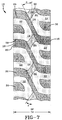
- Fig. 8 shows the preferred embodiment of the invention.
- Each lug 14 has two wide sections 22 interconnected by a narrow section 24.
- Each wide section 22 has a shoulder groove 30 and the narrow section 24 is intersected by a linear groove 32.
- each shoulder groove 30 has a depth of full nonskid NSK.
- the linear grooves 32 are angled from the centerline at an angle ⁇ in the range of 15 to 70 degrees.
- Each lug 14 further has an offset groove 36 that extends at least partially along a shoulder portion of each wide section 22.
- Each offset groove 36 has a width in the range of 3% to 15% of the tread width TW.
- Each offset groove 36 extends from either a leading edge 26 or a trailing edge 28 to the shoulder groove 30 of the respective wide section 22.
- Each wide groove 20 approaches an angle perpendicular to the centerline as it approaches the respective shoulder 16,18. However, the wide groove 20 may open slightly as it meets the respective shoulder 16,18 to enable proper ejection of mud and foreign materials.
- the tire 10 of the invention may be molded as one skilled in the art would typically mold a tire.
- the off-road pneumatic tire 10 of this invention will generally have a nominal rim diameter of at least 20 inches.
- the tire may also have a varying pitch relationship.
Landscapes
- Engineering & Computer Science (AREA)
- Mechanical Engineering (AREA)
- Tires In General (AREA)
Applications Claiming Priority (2)
| Application Number | Priority Date | Filing Date | Title |
|---|---|---|---|
| US09/465,037 US6298890B1 (en) | 1999-12-16 | 1999-12-16 | Off-road tire |
| US465037 | 1999-12-16 |
Publications (3)
| Publication Number | Publication Date |
|---|---|
| EP1108565A2 true EP1108565A2 (de) | 2001-06-20 |
| EP1108565A3 EP1108565A3 (de) | 2002-09-25 |
| EP1108565B1 EP1108565B1 (de) | 2005-04-27 |
Family
ID=23846258
Family Applications (1)
| Application Number | Title | Priority Date | Filing Date |
|---|---|---|---|
| EP00126683A Expired - Lifetime EP1108565B1 (de) | 1999-12-16 | 2000-12-05 | Geländegängiger Reifen |
Country Status (7)
| Country | Link |
|---|---|
| US (1) | US6298890B1 (de) |
| EP (1) | EP1108565B1 (de) |
| JP (1) | JP2001191738A (de) |
| CN (1) | CN1212944C (de) |
| BR (1) | BR0005709A (de) |
| CA (1) | CA2320530A1 (de) |
| DE (1) | DE60019706T2 (de) |
Families Citing this family (16)
| Publication number | Priority date | Publication date | Assignee | Title |
|---|---|---|---|---|
| US6533007B1 (en) * | 2000-03-02 | 2003-03-18 | Mcmannis Lee A. | Tire having sidewall extensions at opposite ends of each tread element |
| JP4072708B2 (ja) * | 2000-12-28 | 2008-04-09 | 福山ゴム工業株式会社 | クッションタイヤ |
| US7341082B2 (en) * | 2004-12-28 | 2008-03-11 | The Goodyear Tire & Rubber Company | Shoulder ribs for pneumatic tires |
| DE102006002050B4 (de) * | 2005-01-17 | 2012-06-14 | Toyo Tire & Rubber Co., Ltd. | Luftreifen |
| JP4287877B2 (ja) * | 2006-11-13 | 2009-07-01 | 住友ゴム工業株式会社 | 不整地走行用の空気入りタイヤ |
| EP2091760B1 (de) * | 2006-11-24 | 2012-08-15 | Alliance Tire Co. | Reifen für landwirtschaftliches fahrzeug |
| JP4912130B2 (ja) * | 2006-12-05 | 2012-04-11 | 住友ゴム工業株式会社 | ラグ付きタイヤ |
| US8136562B2 (en) | 2006-12-29 | 2012-03-20 | Bridgestone Firestone North American Tire, Llc | Tire bead insulation |
| US7926533B2 (en) | 2007-10-31 | 2011-04-19 | The Goodyear Tire & Rubber Company, Inc. | Pneumatic tire with increased lower sidewall durability |
| US8056592B2 (en) * | 2007-10-31 | 2011-11-15 | The Goodyear Tire + Rubber Company, Inc. | Grip tire with added puncture protection |
| US8196626B2 (en) * | 2009-01-08 | 2012-06-12 | Tsai Jen Lo | Tire with asymmetric tread profile |
| US8905097B2 (en) | 2012-02-01 | 2014-12-09 | Bridgestone Americas Tire Operations, Llc | Agricultural tire tread |
| WO2018094026A1 (en) | 2016-11-17 | 2018-05-24 | Bridgestone Americas Tire Operations, Llc | Pneumatic tire having dampening element adhered to air barrier layer |
| US11027580B2 (en) * | 2018-01-05 | 2021-06-08 | Irobot Corporation | Wheel for autonomous cleaning robot |
| EP3962756A4 (de) | 2019-04-29 | 2023-01-04 | Bridgestone Corporation | Seitenwandträger für luftreifen |
| CN110182003A (zh) * | 2019-07-04 | 2019-08-30 | 山东汉正橡胶工业有限公司 | 一种高性能半热熔防爆胎 |
Citations (4)
| Publication number | Priority date | Publication date | Assignee | Title |
|---|---|---|---|---|
| US4254811A (en) * | 1977-01-25 | 1981-03-10 | Compagnie Generale Des Etablissements Michelin | Pneumatic tires |
| JPH05278415A (ja) * | 1992-04-02 | 1993-10-26 | Bridgestone Corp | 空気入りタイヤ |
| EP0719660A2 (de) * | 1994-12-27 | 1996-07-03 | The Goodyear Tire & Rubber Company | Lauffläche für Luftreifen und Luftreifen mit solcher Lauffläche |
| WO1998033669A1 (en) * | 1997-02-04 | 1998-08-06 | The Goodyear Tire & Rubber Company S | Industrial service agricultural tire |
Family Cites Families (24)
| Publication number | Priority date | Publication date | Assignee | Title |
|---|---|---|---|---|
| GB405609A (en) * | 1932-07-06 | 1934-02-06 | Dunlop Rubber Co | Improvements in traction treads |
| FR768057A (fr) * | 1933-02-02 | 1934-07-31 | Fr B F Goodrich Soc | Perfectionnements apportés aux pneumatiques pour véhicules |
| US2113527A (en) | 1937-12-28 | 1938-04-05 | Firestone Tire & Rubber Co | Tire construction |
| BE463787A (de) | 1945-03-12 | |||
| US3196920A (en) * | 1964-03-16 | 1965-07-27 | Louis Fishman & Co Inc | Tire construction |
| FR2053873A5 (de) * | 1969-07-21 | 1971-04-16 | Michelin & Cie | |
| FR2157211A7 (de) * | 1971-10-21 | 1973-06-01 | Kleber Colombes | |
| JPS577706A (en) * | 1980-06-13 | 1982-01-14 | Bridgestone Corp | Pneumatic radial tire for heavy load |
| JPS5727104A (en) * | 1980-07-25 | 1982-02-13 | Nippon Enbairo Kogyo Kk | Filter press |
| US4727917A (en) * | 1983-06-02 | 1988-03-01 | The Firestone Tire & Rubber Company | Alternating lug tire |
| JPS6322703A (ja) * | 1986-07-15 | 1988-01-30 | Bridgestone Corp | 空気入りタイヤ |
| JPH02128905A (ja) * | 1988-11-09 | 1990-05-17 | Sumitomo Rubber Ind Ltd | Atv用タイヤ |
| DE3907074A1 (de) * | 1989-03-04 | 1990-09-06 | Uniroyal Englebert Gmbh | Fahrzeugluftreifen |
| JPH0374207A (ja) * | 1989-05-01 | 1991-03-28 | Kazuo Murazaki | 自動車のタイヤ |
| JP2857493B2 (ja) * | 1990-11-30 | 1999-02-17 | 住友ゴム工業 株式会社 | 空気入りタイヤ |
| US5188683A (en) * | 1991-04-22 | 1993-02-23 | The Goodyear Tire & Rubber Company | Pneumatic tire for agricultural or logging use |
| JP3424975B2 (ja) * | 1994-03-11 | 2003-07-07 | 住友ゴム工業株式会社 | 空気入りタイヤ |
| JP3579090B2 (ja) * | 1994-07-27 | 2004-10-20 | 株式会社ブリヂストン | 重荷重用空気入りタイヤ |
| JP3511413B2 (ja) * | 1995-02-01 | 2004-03-29 | 株式会社ブリヂストン | 空気入りタイヤ |
| JPH09226318A (ja) * | 1996-02-23 | 1997-09-02 | Bridgestone Corp | 悪路走行用空気入りラジアルタイヤ |
| USD402245S (en) * | 1997-09-22 | 1998-12-08 | The Goodyear Tire & Rubber Company | Tread for a tire |
| JP4000214B2 (ja) * | 1998-02-06 | 2007-10-31 | 株式会社ブリヂストン | 重荷重用空気入りラジアル・タイヤ |
| JPH11222171A (ja) * | 1998-02-07 | 1999-08-17 | Bridgestone Corp | ゴムクロ−ラ |
| US6189586B1 (en) * | 1998-10-15 | 2001-02-20 | Warren L. Guidry | Pneumatic rubber tire for on/off-road vehicles |
-
1999
- 1999-12-16 US US09/465,037 patent/US6298890B1/en not_active Expired - Fee Related
-
2000
- 2000-09-25 CA CA002320530A patent/CA2320530A1/en not_active Abandoned
- 2000-12-04 BR BR0005709-6A patent/BR0005709A/pt not_active IP Right Cessation
- 2000-12-05 DE DE60019706T patent/DE60019706T2/de not_active Expired - Fee Related
- 2000-12-05 EP EP00126683A patent/EP1108565B1/de not_active Expired - Lifetime
- 2000-12-12 JP JP2000377459A patent/JP2001191738A/ja active Pending
- 2000-12-18 CN CNB001356755A patent/CN1212944C/zh not_active Expired - Fee Related
Patent Citations (4)
| Publication number | Priority date | Publication date | Assignee | Title |
|---|---|---|---|---|
| US4254811A (en) * | 1977-01-25 | 1981-03-10 | Compagnie Generale Des Etablissements Michelin | Pneumatic tires |
| JPH05278415A (ja) * | 1992-04-02 | 1993-10-26 | Bridgestone Corp | 空気入りタイヤ |
| EP0719660A2 (de) * | 1994-12-27 | 1996-07-03 | The Goodyear Tire & Rubber Company | Lauffläche für Luftreifen und Luftreifen mit solcher Lauffläche |
| WO1998033669A1 (en) * | 1997-02-04 | 1998-08-06 | The Goodyear Tire & Rubber Company S | Industrial service agricultural tire |
Non-Patent Citations (1)
| Title |
|---|
| PATENT ABSTRACTS OF JAPAN vol. 018, no. 055 (M-1550), 28 January 1994 (1994-01-28) -& JP 05 278415 A (BRIDGESTONE CORP), 26 October 1993 (1993-10-26) * |
Also Published As
| Publication number | Publication date |
|---|---|
| CN1299746A (zh) | 2001-06-20 |
| DE60019706T2 (de) | 2006-01-19 |
| BR0005709A (pt) | 2001-07-31 |
| EP1108565B1 (de) | 2005-04-27 |
| DE60019706D1 (de) | 2005-06-02 |
| US6298890B1 (en) | 2001-10-09 |
| CA2320530A1 (en) | 2001-06-16 |
| JP2001191738A (ja) | 2001-07-17 |
| CN1212944C (zh) | 2005-08-03 |
| EP1108565A3 (de) | 2002-09-25 |
Similar Documents
| Publication | Publication Date | Title |
|---|---|---|
| US6298890B1 (en) | Off-road tire | |
| US8813800B2 (en) | Pneumatic tire | |
| CA2006991C (en) | Pneumatic tire with side wall lugs aligned with the inner tread surface | |
| US8006730B2 (en) | Pneumatic tire with tread having circumferential main grooves | |
| JP2617713B2 (ja) | 重荷重用空気入りラジアルタイヤ | |
| JP5856051B2 (ja) | 重荷重用タイヤ | |
| EP1120294B1 (de) | Geländeluftreifen | |
| US5549146A (en) | Vehicle tire with wiper rib member | |
| EP0588623A1 (de) | Radialer Reifen | |
| US4412575A (en) | Heavy load pneumatic radial tire | |
| EP1034945A1 (de) | Luftreifen | |
| JPH09272312A (ja) | 重荷重用空気入りタイヤ | |
| RU2717113C2 (ru) | Протектор шины для транспортного средства сельскохозяйственного назначения | |
| JPS6143201B2 (de) | ||
| JPH06320914A (ja) | 重荷重用空気入りラジアルタイヤ | |
| EP1237736B1 (de) | Fahrzeugräderluftreifen, insbesondere für mittel-kraftfahrzeug wie z.b. lastkraftfahrzeuge und dergleichen | |
| JP2004075056A (ja) | オフザロードタイヤ | |
| US6748988B2 (en) | Pneumatic tire having lug grooves | |
| JPH0335601Y2 (de) | ||
| JP3535238B2 (ja) | 重荷重用空気入りラジアルタイヤ | |
| EP0524567B1 (de) | Lauffläche für Reifen | |
| JPH11334321A (ja) | 空気入りラジアルタイヤ | |
| US20080142135A1 (en) | Pneumatic tire with decoupling groove | |
| JP2816853B2 (ja) | 空気入りラジアルタイヤ | |
| JPH08268010A (ja) | 空気入りタイヤ |
Legal Events
| Date | Code | Title | Description |
|---|---|---|---|
| PUAI | Public reference made under article 153(3) epc to a published international application that has entered the european phase |
Free format text: ORIGINAL CODE: 0009012 |
|
| AK | Designated contracting states |
Kind code of ref document: A2 Designated state(s): AT BE CH CY DE DK ES FI FR GB GR IE IT LI LU MC NL PT SE TR |
|
| AX | Request for extension of the european patent |
Free format text: AL;LT;LV;MK;RO;SI |
|
| PUAL | Search report despatched |
Free format text: ORIGINAL CODE: 0009013 |
|
| AK | Designated contracting states |
Kind code of ref document: A3 Designated state(s): AT BE CH CY DE DK ES FI FR GB GR IE IT LI LU MC NL PT SE TR |
|
| AX | Request for extension of the european patent |
Free format text: AL;LT;LV;MK;RO;SI |
|
| 17P | Request for examination filed |
Effective date: 20030325 |
|
| AKX | Designation fees paid |
Designated state(s): DE FR GB IT |
|
| 17Q | First examination report despatched |
Effective date: 20030519 |
|
| GRAP | Despatch of communication of intention to grant a patent |
Free format text: ORIGINAL CODE: EPIDOSNIGR1 |
|
| GRAS | Grant fee paid |
Free format text: ORIGINAL CODE: EPIDOSNIGR3 |
|
| GRAA | (expected) grant |
Free format text: ORIGINAL CODE: 0009210 |
|
| AK | Designated contracting states |
Kind code of ref document: B1 Designated state(s): DE FR GB IT |
|
| REG | Reference to a national code |
Ref country code: GB Ref legal event code: FG4D |
|
| REG | Reference to a national code |
Ref country code: IE Ref legal event code: FG4D |
|
| REF | Corresponds to: |
Ref document number: 60019706 Country of ref document: DE Date of ref document: 20050602 Kind code of ref document: P |
|
| ET | Fr: translation filed | ||
| PLBE | No opposition filed within time limit |
Free format text: ORIGINAL CODE: 0009261 |
|
| STAA | Information on the status of an ep patent application or granted ep patent |
Free format text: STATUS: NO OPPOSITION FILED WITHIN TIME LIMIT |
|
| 26N | No opposition filed |
Effective date: 20060130 |
|
| PGFP | Annual fee paid to national office [announced via postgrant information from national office to epo] |
Ref country code: GB Payment date: 20061106 Year of fee payment: 7 |
|
| PGFP | Annual fee paid to national office [announced via postgrant information from national office to epo] |
Ref country code: IT Payment date: 20071217 Year of fee payment: 8 |
|
| PGFP | Annual fee paid to national office [announced via postgrant information from national office to epo] |
Ref country code: DE Payment date: 20071228 Year of fee payment: 8 |
|
| PGFP | Annual fee paid to national office [announced via postgrant information from national office to epo] |
Ref country code: FR Payment date: 20071204 Year of fee payment: 8 |
|
| GBPC | Gb: european patent ceased through non-payment of renewal fee |
Effective date: 20071205 |
|
| PG25 | Lapsed in a contracting state [announced via postgrant information from national office to epo] |
Ref country code: GB Free format text: LAPSE BECAUSE OF NON-PAYMENT OF DUE FEES Effective date: 20071205 |
|
| REG | Reference to a national code |
Ref country code: FR Ref legal event code: ST Effective date: 20090831 |
|
| PG25 | Lapsed in a contracting state [announced via postgrant information from national office to epo] |
Ref country code: DE Free format text: LAPSE BECAUSE OF NON-PAYMENT OF DUE FEES Effective date: 20090701 |
|
| PG25 | Lapsed in a contracting state [announced via postgrant information from national office to epo] |
Ref country code: FR Free format text: LAPSE BECAUSE OF NON-PAYMENT OF DUE FEES Effective date: 20081231 |
|
| PG25 | Lapsed in a contracting state [announced via postgrant information from national office to epo] |
Ref country code: IT Free format text: LAPSE BECAUSE OF NON-PAYMENT OF DUE FEES Effective date: 20081205 |