EP1103384A1 - Aufzeichnungsvorrichtung und datensteuerverfahren dafür - Google Patents
Aufzeichnungsvorrichtung und datensteuerverfahren dafür Download PDFInfo
- Publication number
- EP1103384A1 EP1103384A1 EP00927744A EP00927744A EP1103384A1 EP 1103384 A1 EP1103384 A1 EP 1103384A1 EP 00927744 A EP00927744 A EP 00927744A EP 00927744 A EP00927744 A EP 00927744A EP 1103384 A1 EP1103384 A1 EP 1103384A1
- Authority
- EP
- European Patent Office
- Prior art keywords
- dot
- group
- groups
- recording
- dot formation
- Prior art date
- Legal status (The legal status is an assumption and is not a legal conclusion. Google has not performed a legal analysis and makes no representation as to the accuracy of the status listed.)
- Granted
Links
Images


Classifications
-
- B—PERFORMING OPERATIONS; TRANSPORTING
- B41—PRINTING; LINING MACHINES; TYPEWRITERS; STAMPS
- B41J—TYPEWRITERS; SELECTIVE PRINTING MECHANISMS, i.e. MECHANISMS PRINTING OTHERWISE THAN FROM A FORME; CORRECTION OF TYPOGRAPHICAL ERRORS
- B41J2/00—Typewriters or selective printing mechanisms characterised by the printing or marking process for which they are designed
- B41J2/005—Typewriters or selective printing mechanisms characterised by the printing or marking process for which they are designed characterised by bringing liquid or particles selectively into contact with a printing material
- B41J2/01—Ink jet
- B41J2/015—Ink jet characterised by the jet generation process
- B41J2/04—Ink jet characterised by the jet generation process generating single droplets or particles on demand
- B41J2/045—Ink jet characterised by the jet generation process generating single droplets or particles on demand by pressure, e.g. electromechanical transducers
- B41J2/04501—Control methods or devices therefor, e.g. driver circuits, control circuits
- B41J2/04543—Block driving
-
- B—PERFORMING OPERATIONS; TRANSPORTING
- B41—PRINTING; LINING MACHINES; TYPEWRITERS; STAMPS
- B41J—TYPEWRITERS; SELECTIVE PRINTING MECHANISMS, i.e. MECHANISMS PRINTING OTHERWISE THAN FROM A FORME; CORRECTION OF TYPOGRAPHICAL ERRORS
- B41J2/00—Typewriters or selective printing mechanisms characterised by the printing or marking process for which they are designed
- B41J2/005—Typewriters or selective printing mechanisms characterised by the printing or marking process for which they are designed characterised by bringing liquid or particles selectively into contact with a printing material
- B41J2/01—Ink jet
- B41J2/015—Ink jet characterised by the jet generation process
- B41J2/04—Ink jet characterised by the jet generation process generating single droplets or particles on demand
- B41J2/045—Ink jet characterised by the jet generation process generating single droplets or particles on demand by pressure, e.g. electromechanical transducers
- B41J2/04501—Control methods or devices therefor, e.g. driver circuits, control circuits
- B41J2/0458—Control methods or devices therefor, e.g. driver circuits, control circuits controlling heads based on heating elements forming bubbles
-
- B—PERFORMING OPERATIONS; TRANSPORTING
- B41—PRINTING; LINING MACHINES; TYPEWRITERS; STAMPS
- B41J—TYPEWRITERS; SELECTIVE PRINTING MECHANISMS, i.e. MECHANISMS PRINTING OTHERWISE THAN FROM A FORME; CORRECTION OF TYPOGRAPHICAL ERRORS
- B41J2/00—Typewriters or selective printing mechanisms characterised by the printing or marking process for which they are designed
- B41J2/005—Typewriters or selective printing mechanisms characterised by the printing or marking process for which they are designed characterised by bringing liquid or particles selectively into contact with a printing material
- B41J2/01—Ink jet
- B41J2/135—Nozzles
- B41J2/145—Arrangement thereof
- B41J2/15—Arrangement thereof for serial printing
-
- B—PERFORMING OPERATIONS; TRANSPORTING
- B41—PRINTING; LINING MACHINES; TYPEWRITERS; STAMPS
- B41J—TYPEWRITERS; SELECTIVE PRINTING MECHANISMS, i.e. MECHANISMS PRINTING OTHERWISE THAN FROM A FORME; CORRECTION OF TYPOGRAPHICAL ERRORS
- B41J2/00—Typewriters or selective printing mechanisms characterised by the printing or marking process for which they are designed
- B41J2/005—Typewriters or selective printing mechanisms characterised by the printing or marking process for which they are designed characterised by bringing liquid or particles selectively into contact with a printing material
- B41J2/01—Ink jet
- B41J2/21—Ink jet for multi-colour printing
- B41J2/2103—Features not dealing with the colouring process per se, e.g. construction of printers or heads, driving circuit adaptations
-
- G—PHYSICS
- G06—COMPUTING OR CALCULATING; COUNTING
- G06K—GRAPHICAL DATA READING; PRESENTATION OF DATA; RECORD CARRIERS; HANDLING RECORD CARRIERS
- G06K15/00—Arrangements for producing a permanent visual presentation of the output data, e.g. computer output printers
- G06K15/02—Arrangements for producing a permanent visual presentation of the output data, e.g. computer output printers using printers
- G06K15/10—Arrangements for producing a permanent visual presentation of the output data, e.g. computer output printers using printers by matrix printers
- G06K15/102—Arrangements for producing a permanent visual presentation of the output data, e.g. computer output printers using printers by matrix printers using ink jet print heads
-
- G—PHYSICS
- G06—COMPUTING OR CALCULATING; COUNTING
- G06K—GRAPHICAL DATA READING; PRESENTATION OF DATA; RECORD CARRIERS; HANDLING RECORD CARRIERS
- G06K2215/00—Arrangements for producing a permanent visual presentation of the output data
- G06K2215/0002—Handling the output data
- G06K2215/0077—Raster outputting to the print element(s)
- G06K2215/008—Raster outputting to the print element(s) from more than one raster memory
-
- G—PHYSICS
- G06—COMPUTING OR CALCULATING; COUNTING
- G06K—GRAPHICAL DATA READING; PRESENTATION OF DATA; RECORD CARRIERS; HANDLING RECORD CARRIERS
- G06K2215/00—Arrangements for producing a permanent visual presentation of the output data
- G06K2215/0082—Architecture adapted for a particular function
- G06K2215/0094—Colour printing
Definitions
- This invention relates to a recording apparatus and a data control method therein, and more particularly to a data control technique for driving dot formation means in the recording apparatus.
- a recording head is provided with dot formation means comprising a plurality of nozzle orifices, pressure generating chambers communicating with the nozzle orifices in a one-to-one correspondence, and pressure generating elements such as piezoelectric vibrators for pressurizing ink in the pressure generating chambers, thereby jetting ink drops from the corresponding nozzle orifices and a head driver circuit (drive means) comprising a plurality of switching elements for determining whether or not a drive signal is to be applied to the pressure generating elements based on record data, and ink drops are selectively jetted from predetermined nozzle orifices depending on which of the switching elements are driven, whereby predetermined recording is executed on a medium such as recording paper.
- Such record data is provided by expanding record information input from a printer driver in memory, as described with reference to
- Fig. 6 record information created with a printer driver 96 installed in a personal computer is input to a printer via various interfaces for each page (step ST10).
- the one-page record information is stored as data in an input buffer 44A formed in DRAM (Dynamic Random Access Memory) by automatically switching the interfaces (step ST20).
- a control section CPU executes command analysis on the data stored in the input buffer 44A one byte at a time and determines whether the data is record data or a record processing command (step ST30).
- control section transfers the record data undergoing the command analysis to an image buffer 44B (first storage means) in the DRAM as image data (step ST40).
- the image buffer 44B is configured corresponding to the head structure; for example, in a four-color printer comprising 96 nozzles per row, a recording head 10 is formed with nozzle orifices belonging to five groups (five rows) and thus the image buffer 44B is formed for as much as the five groups
- nozzle orifices belonging to five groups refers to nozzle orifices belonging to three color groups for jetting three color inks of cyan (C), magenta (M).
- nozzle orifices belonging to a first black group (BK1) for jetting black ink on the monochrome recording and stopping jetting ink drops on the color recording and nozzle orifices belonging to a second black group (BK2) for jetting black ink on the color recording and on the monochrome recording.
- BK1 first black group
- BK2 second black group
- one-pass data of nozzle #1 corresponding to the yellow (Y) group is transferred to the image buffer 44B in a raster direction (in the order of a, b, c) and after the data transfer concerning the nozzle #1 terminates, similar processing is repeated for executing data transfer concerning nozzles #2, #3, ... #96.
- step ST50 data of one word (a and b rows in the image buffer) is transferred from the image buffer 44B to an output buffer 44C (second storage means) formed of SRAM (Static Random Access Memory) of a head control unit (step ST50).
- SRAM Static Random Access Memory
- step ST51 the zeroth bit of one word is converted from raster into row from #1 to #96 and is serially transferred to a head driver circuit (step ST51). This operation is repeated 16 times, whereby one-word transfer is complete (step ST52). Similar transfer is also executed for other four groups. Then, an interrupt is generated and processing for the next one word is performed (step ST53). After this, such processing is repeated.
- serial conversion of the record data in the output buffer 44C and serial transfer to the head driver circuit are also executed for the nozzle orifices corresponding to a group jetting no ink drops and thus there is a problem of occurrence of fruitless processing time in the control section.
- serial conversion of the record data in the output buffer 44C and serial transfer to the head driver circuit are executed for all the five groups although recording is executed only with the nozzle orifices corresponding to the three color groups of cyan (C), magenta (M), and yellow (Y) and the nozzle orifices corresponding to the second black group (BK2) and no ink drops are jetted from the nozzle orifices corresponding to the first black group (BK1).
- serial conversion in the output buffer 44C and serial transfer to the head driver circuit are executed for the first black group (BK1) not used for recording.
- serial conversion of the record data in the output buffer 44C and serial transfer to the head driver circuit are executed for all the five groups although recording is executed only with the nozzle orifices corresponding to the first black group (BK1) and the nozzle orifices corresponding to the second black group (BK2) and no ink drops are jetted from the nozzle orifices corresponding to cyan (C), magenta (M), yellow (Y).
- serial conversion of the data indicating that no ink is jetted ("0" data) in the output buffer 44C as record data and serial transfer of the data indicating that no ink is jetted ("0" data) to the head driver circuit as record data are executed for cyan (C), magenta (M), and yellow (Y) not used for recording.
- a recording apparatus comprising:
- the mode fixing signal may be a signal via a hardware signal line or a software command.
- serial conversion to the record data and serial transfer of the record data to the drive means become unnecessary for the group subjected to drive control by the mode fixing signal, so that fruitless processing time can be eliminated. Therefore, as compared with the case where serial conversion to the record data and serial transfer of the record data to the head driver circuit are performed for all groups, fruitless data processing time and fruitless data transfer time can be eliminated, so that the throughput of recording can be enhanced.
- the fixing signal output means outputs a signal indicating that no dot is formed as the mode fixing signal to the drive means for the dot formation means belonging to the group not used for recording, and the mode fixing means fixes the dot formation means belonging to the corresponding group to a condition of forming no dots based on the mode fixing signal.
- the fixing signal output means simply outputs the mode fixing signal for the group wherein no dots are formed in all dot formation means, whereby the mode fixing means fixes the drive condition in hardware assuming that no ink drops are formed for the dot formation means belonging to the group.
- the storage means may comprise storage regions as many as the maximum number of groups having a possibility that they will be used at the same time or more.
- the control means reserves as many storage regions as the number of groups used for the current recording each time in the storage means.
- the storage regions of the second storage means are reserved only for the areas required for the record operation and thus in the control using the record data, the operation of forming dots by the dot formation means in all groups (for example, the flushing operation in an ink jet recording apparatus or the like) becomes impossible.
- the dot formation means belonging to all groups if a signal indicating that a dot is formed is output for all groups as the mode fixing signal, ink drops can be jetted from nozzle orifices in all groups if the storage means is short of storage region.
- the control means uses the excess storage region for serial transfer of the record data.
- the control means uses the excess storage region for any other processing, such as a communication buffer.
- the dot formation means may be classified into color groups for a plurality of colors for color recording, a first black group for recording in black on the monochrome recording and stopping dot formation on the color recording, and a second black group for recording in black at both the monochrome recording time and the color recording time.
- the fixing signal output means outputs the mode fixing signal for the dot formation means belonging to the first black group on the color recording and outputs the mode fixing signal for the dot formation means belonging to the color groups on the monochrome recording.
- the fixing signal output means may output a signal indicating that a dot is formed by the dot formation means belonging to all groups to the drive means as the mode fixing signal, and the mode fixing means may fix the dot formation means belonging to all groups to a condition of forming a dot based on the mode fixing signal.
- the operation of forming dots in all groups for example, the flushing operation in an ink jet recording apparatus or the like is possible if record data is not used.
- the drive means may comprise a shift register for converting the record data transferred in series into parallel form.
- the mode fixing means can fix the dot formation condition for the predetermined group to the condition defined by the fixing signal on a way of a signal transfer path from the shift register to the dot formation means.
- the drive means may comprise a shift register for converting the record data transferred in series into parallel form.
- the mode fixing means may cause the shift register to hold the data defined by the mode fixing signal
- this method comprises the steps of:
- a signal indicating that no dot is formed as the mode fixing signal is output to the drive means for the dot formation means belonging to the group not used for recording, and the dot formation means belonging to the corresponding group is fixed to a condition of forming no dots based on the mode fixing signal.
- a storage region may be reserved in the storage means only for the group for which the mode fixing signal is not output and reserving a storage region in the storage means may be skipped for the group for which the mode fixing signal is output
- Fig. 1 is a block diagram to show the general configuration of an ink jet recording apparatus incorporating the invention.
- a scanner 120 and a color ink jet printer 100 are connected to a computer 90 and a predetermined program is loaded into the computer 90 and is executed, whereby the ink jet recording apparatus 1 serves as a recording apparatus as a whole.
- the computer 90 comprises the following members connected by a bus 80, centering on a CPU 81 for executing various types of computation processing to control the operation concerning image processing following the program: ROM 82 previously stores programs and data required for the CPU 81 to execute various types of computation processing and likewise RAM 83 is memory where various programs and data required for the CPU 81 to execute various types of computation processing are temporarily read and written.
- An input interface 84 is responsible for inputting signals from the scanner 120 and a keyboard 140 and an output interface 85 is responsible for outputting data to the ink jet printer 100.
- a CRTC 86 controls signal output to a CRT 210 that can produce color display and a disk controller (DDC) 87 controls transfer of data to and from a hard disk 160, a flexible drive 150, or a CD-ROM drive (not shown).
- DDC disk controller
- Various programs loaded into the RAM 83 for execution, various programs provided in the device driver format, various programs provided in the disk driver format, and the like are stored on the hard disk 160.
- a serial input interface (SIO) 88 is connected to the bus 80.
- the SIO 88 is connected to a modem 180 and is connected through the modem 180 to a public telephone network PNT.
- the computer 90 is connected to an external network through the SIO 88 and the modem 180 and can also be connected to a specific server SV, thereby downloading a necessary program for image processing onto hard disk.
- a necessary program can also be down loaded with flexible disk FD or CD-ROM and be executed by the computer 90.
- Fig. 2 is a block diagram to show the software configuration of the ink jet recording apparatus of the embodiment.
- an application program 95 operates under a predetermined operating system.
- a video driver 91 and a printer driver 96 are built in the operating system and intermediate image data to be transferred to the ink jet printer 100 is output through the drivers 91 and 96 from the application program 95.
- the application program 95 for retouching an image, etc. reads an image from the scanner 12 and performs predetermined processing for the read image, then displays an image on a CRT display 21 through the video driver 91.
- Data ORG supplied from the scanner 12 is original color image data read from a color original and consisting of three color components of red (R), green (G), and blue (B).
- the printer driver 96 of the computer 90 receives image information from the application program 95 and the printer driver 96 converts the image information into signals that can be processed in the ink jet printer 100 (here, signals converted into multilevel for the colors of cyan, magenta, yellow, and black)
- the printer driver 96 contains a resolution conversion module 97, a color correction module 98, a color correction table LUT, a halftone module 99, and a rasterizer 94.
- the printer driver 96 also serves as stop command means for outputting a stop signal indicating that jetting of ink drops is stopped continuously for a predetermined time for nozzle orifices belonging to a specific group, of a plurality of nozzle orifices, as described later.
- the resolution conversion module 97 plays a role in converting the resolution of color image data handled by the application program 95, namely, the number of pixels per unit length into the resolution that can be handled by the printer driver 96. Since the image data thus undergoing the resolution conversion is still image information consisting of three colors of R, G, and B, the color correction module 98 converts the image data into data of each color of cyan (C), magenta (M), yellow (Y), and black (BK) used by the ink jet printer 100 for each pixel while referencing the color correction table LUT. The data thus undergoing color correction has a gradation value in the range of 256 levels of gray, etc., for example.
- the halftone module 99 executes halftone processing to represent a predetermined gradation value in the ink jet printer 100 by forming dots in a dispersion manner.
- the image data thus processed is sorted by the rasterizer 94 in the order of data to be transferred to the ink jet printer 100 and is output as final image data FNL (record information).
- the ink jet printer 100 only executes the dot formation in accordance with the image data FNL and does not perform image processing.
- the printer driver 96 in the computer 90 does not adjust a drive signal in the ink jet printer 100, etc., but can also set a plurality of pulse signals contained in the drive signal using a function of bi-directional communication with the ink jet printer 100.
- Fig. 3 is a perspective view to show the main part of the ink jet printer.
- a carriage 101 is connected to a carriage motor 103 of a carriage mechanism 12 via a timing belt 102 and is guided by a guide member 104 so as to reciprocate in the paper width direction of recording paper 105.
- the ink jet printer 100 is formed with a paper transport mechanism 11 using a paper transport roller 106
- An ink jet recording head 10 is attached to the face of the carriage 101 opposed to the recording paper 106, in the example shown in the figure, the lower face.
- the recording head 10 receives supply of ink from two ink cartridges 107K and 107F placed on the carriage 101 and jets ink drops on the recording paper 105 to form dots as the carriage 101 is moved, thereby recording an image and character on the recording paper 105.
- stored black (BK) ink is supplied to the recording head 10.
- the ink cartridge 107F is provided for color ink and is formed with a plurality of ink storage sections 107C, 107M, and 107Y for storing color inks. Cyan (C) ink, magenta (M) ink, and yellow (Y) ink are stored in the ink storage sections 107C, 107M, and 107Y separately and are supplied to the recording head 10 separately.
- a capping unit 108 is formed in a non-storage region of the ink jet printer 100 and seals the nozzle orifices of the recording head 10 while recording stops. Therefore, an increase in viscosity of ink or formation of an ink film because a solvent is scattered from ink while recording stops can be suppressed. Therefore, the nozzles can be prevented from being clogged while recording stops.
- the capping unit 108 receives ink drops from the recording head 10 by the flushing operation performed during the record operation.
- a wiping unit 109 is placed in the proximity of the capping unit 108 and wipes the surface of the recording head 10 with a blade, etc., for wiping out ink leavings and paper powder deposited on the surface of the recording head 10.
- Fig. 4 is a schematic representation to show a nozzle arrangement formed on the recording head 10 shown in Fig. 3.
- the recording head 10 is formed with five rows (five groups) of nozzles 111 and the nozzles 111 are nozzle orifices belonging to three color groups for jetting three color inks of cyan (C), magenta (M), and yellow (Y), nozzle orifices belonging to a first black group (BK1) for jetting black ink on the monochrome recording and stopping jetting ink drops on the color recording, and nozzle orifices belonging to a second black group (BK2) for jetting black ink on the color recording and on the monochrome recording.
- BK1 first black group
- BK2 second black group
- the nozzle orifices corresponding to cyan (C), magenta (M), yellow (Y), and the second black group (BK2) are arranged on the same lines with spacing of 1/180 inches; the nozzle orifices belonging to the first black group (BK1) are formed at 1/360-inch shift positions from the nozzle orifices.
- Fig. 5 is a functional block diagram of the ink jet printer 100 of the embodiment.
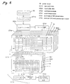
- Fig. 6 is a schematic representation to show the data processing contents performed in the ink jet printer 100.
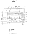
- Fig. 7 is a block diagram of a head driver circuit formed in the recording head 10.
- the ink jet printer 100 is made up of a print controller 40 and a print engine 5
- the print controller 40 comprises an interface 43 for receiving image data FNL (record information) containing multilevel hierarchical information from the computer 90 (see Figs. 1 and 2) and the like, an input buffer 44A and an image buffer 44B implemented as DRAM for storing various pieces of data such as the record information containing multilevel hierarchical information (first storage means), an output buffer 44C implemented as SRAM (second storage means), ROM 45 storing routines, etc., for performing various types of data processing, a control section 46 implemented as a CPU, etc., an oscillation circuit 47, a drive signal generator circuit 48 for generating a drive signal COM sent to the recording head 10, the drive signal generator circuit 48, and an interface 49 for transmitting print data expanded into dot pattern data and the drive signal to the print engine 5.
- the basic operation in the print controller 40 is similar to that of the ink jet recording apparatus in the related art; as shown in Fig. 5, record information created with the printer driver 96 installed in the personal computer is input to the printer via various interfaces for each page (step ST10). At this time, the one-page record information is stored as data in the input buffer 44A formed in the DRAM by automatically switching the interfaces (step ST20). Next, the control section (CPU) executes command analysis on the data stored in the input buffer 44A one byte at a time and determines whether the data is record data or a record processing command (step ST30).
- the control section transfers the record data undergoing the command analysis to the image buffer 44B (first storage means) in the DRAM as image data (step ST40).
- the image buffer 44B is also configured corresponding to the head structure; for example, in a four-color printer comprising 96 nozzles per row, the recording head 10 is formed with nozzle orifices belonging to five groups (five rows) and thus the image buffer 44B is also formed for as much as the five groups.
- one-pass data of nozzle #1 corresponding to the yellow (Y) group is transferred to the image buffer 44B in a raster direction (in the order of a, b, c) and after the data transfer concerning the nozzle #1 terminates, similar processing is repeated for executing data transfer concerning nozzles #2, #3, . . #96. Similar data expansion and transfer are executed for the nozzle orifices corresponding to the magenta (M) group, the cyan (C) group, the first black group (BK1), and the second black group (BK2).
- one-word data is transferred from the image buffer 44B to the output buffer 44C (second storage means) formed of SRAM of head control unit (step ST50). Since the environment of the embodiment is a 32-bit architecture, a and b rows in the image buffer are transferred. To do this, first the zeroth bit of one word is converted from raster into row from #1 to #96 and is serially transferred to a head driver circuit 50 (step ST51). This operation is repeated 16 times, whereby one-word transfer is complete (step ST52). Similar transfer is also executed for other four groups. Then, an interrupt is generated and processing for the next one word is performed (step ST53). After this, such processing is repeated.
- Fig. 7 is a block diagram of the head driver circuit formed in the recording head of the ink jet recording apparatus of the embodiment.
- the print engine 5 comprises the recording head 10, the paper transport mechanism 11, and the carriage mechanism 12.
- the paper transport mechanism 11 is provided for transporting recording media of recording paper, etc., in sequence for subscanning and the carriage mechanism 12 is provided for main scanning of the recording head 10.
- the recording head 10 jets ink drops from the nozzle orifices 111 at predetermined timing.
- the recording head 10 is provided with the head driver circuit 50 comprising a shift register 13, a latch circuit 14, a level shifter 15, and a switching circuit 16, as shown also in Fig. 7.
- record data SI expanded into dot pattern data in the print controller 40 is serially output to the head driver circuit 50 of the recording head 10 via the interface 49 in synchronization with a clock signal CLK from the oscillation circuit 47 and is serially transferred to the shift register 13 of the recording head 10 and is set in sequence.
- first the data of the most significant bit in the record data SI of nozzles is serially transferred and if the serial transfer of the data of the most significant bit terminates, the data of the second most significant bit is serially transferred.
- the data of the tow-order bits is serially transferred in sequence. If the record data of the bits for all nozzles is set in the elements of the shift register 13, the control section 46 outputs a latch signal (LAT) to the latch circuit 14 at a predetermined timing.
- the latch circuit 14 latches the nozzle selection data set in the shift register 13 in response to the latch signal.
- the nozzle selection data latched by the latch circuit 14 is applied to the level shifter 15 of a voltage converter. For example, if the record data SI is "1," the level shifter 15 converts the data into a voltage value VHV that can be driven by the switching circuit 16, for example, several ten volts.
- the record data SI undergoing the conversion is applied to each switching element of the switching circuit 16 and each element is placed in a connection state.
- a drive signal COM generated by the drive signal generator circuit 48 is applied to each switching element of the switching circuit 16 and when each switching element of the switching circuit 16 is placed in the connection state, the drive signal COM is applied to a pressure generating element 17 connected to the element. Therefore, in the recording head 10, whether or not the drive signal COM is to be applied to the pressure generating element 17 can be controlled based on the nozzle selection data corresponding to the record data SI.
- the drive signal COM can be supplied to the pressure generating element 17 and the pressure generating element 17 is displaced (deformed) by the supplied drive signal COM. Since the element of the switching circuit 16 is placed in a disconnection state in the period during which the record data SI is "0,” supplying the drive signal COM to the pressure generating element 17 is shut off. Each pressure generating element 17 holds the immediately preceding charge in the period during which the nozzle selection data (record data SI) is "0,” so that the immediately preceding displacement state is maintained.
- a pressure generating chamber 113 communicating with the nozzle orifice 111 is shrunk and ink in the pressure generating chamber 113 is pressurized.
- the ink in the pressure generating chamber 113 is jetted as an ink drop, forming a dot on recording paper, etc That is, in the embodiment, the nozzle orifice 111, the pressure generating chamber 113, and the pressure generating element 17 make up dot formation means.
- the recording head 10 is formed with five rows (five groups) of the nozzle orifices 111 as the nozzle orifices 111 belonging to the three color groups for jetting three color inks of cyan (C), magenta (M), and yellow (Y), the nozzle orifices belonging to the first black ink (BK1) group, and the nozzle orifices belonging to the second black ink (BK2) group, as described above, and the pressure generating chambers 113, the pressure generating elements 17, and the switching elements are formed in a one-to-one correspondence with the nozzle orifices 111. Therefore, the pressure generating chambers 113, the pressure generating elements 17, and the switching elements are also classified into five groups for control.
- the image buffer 44B and the output buffer 44C previously described with reference to Fig. 6 are also divided into five groups and in the memories, data expansion from record information to record data SI and data conversion are executed for each group.
- the nozzle orifices 111 used to execute color recording differ from those used to execute monochrome recording. That is, to execute color recording, only the nozzle orifices 111 corresponding to the three color groups of cyan (C), magenta (M), and yellow (Y) and the nozzle orifices 111 corresponding to the second black group (BK2) are used for recording and no ink drops are jetted from the nozzle orifices 111 corresponding to the first black group (BK1).
- nozzle orifices 111 corresponding to the first black group (BK1) and the nozzle orifices 111 corresponding to the second black group (BK2) are used for recording and no ink drops are jetted from the nozzle orifices 111 corresponding to the three color groups of cyan (C), magenta (M), and yellow (Y). Ink drops are jetted from all nozzle orifices 111 at the flushing operation time.
- control section 46 is formed with a fixing signal output section 461 for outputting a mode fixing signal SP corresponding to the fix condition in place of the record data SI corresponding to the nozzle orifices 111 to the head driver circuit 50 for the group wherein the ink drop jet mode is fixed in all nozzle orifices 111.
- the control section 46 is also formed with a storage region setting section 462 for reserving a storage region (buffer area) of the minimum capacity required for the current recording mode, of the five-group storage capacity on the whole in the output buffer 44C. Further, as shown also in Fig.
- the head driver circuit 50 is formed with a mode fixing circuit 18 for fixing the ink jet condition to the condition defined by the mode fixing signal SP for the nozzle orifices 111 belonging to the corresponding group.
- output of the latch circuit 14 and the mode fixing signal SP are input to an AND gate, whereby so long as data indicating that no ink is jetted ("0" data) is input to the AND gate as the mode fixing signal SP, the switching elements of the switching circuit 16 are always fixed off in the group.
- the fixing signal output section 461 of the control section 46 outputs a signal indicating that the jetting mode is fixed to the non-jetting mode as the mode fixing signal SP for the three color groups of cyan (C), magenta (M), and yellow (Y) not used for recording and thus the data indicating that no ink is jetted ("0" data) is input to the AND gate of the head driver circuit 50.
- the storage region setting section 462 of the control section 46 reserves the storage regions (buffer areas) for the two groups of the first black group (BK1) and the second black group (BK2) in the output buffer 44C because serial conversion and serial transfer of the record data SI may be executed only for the first black group (BK1) and the second black group (BK2) required for monochrome recording.
- the fixing signal output section 461 of the control section 46 outputs a signal indicating that the jetting mode is fixed to the non-jetting mode as the mode fixing signal SP for the first black group (BK1) not used for recording and consequently, the data indicating that no ink is jetted ("0" data) is input to the AND gate of the head driver circuit 50 for the group.
- the storage region setting section 462 of the control section 46 reserves the storage regions (buffer areas) for the four groups of the three color groups of cyan (C), magenta (M), and yellow (Y) and the second black group (BK2) in the output buffer 44C because serial conversion and serial transfer of the record data SI may be executed only for the three color groups of cyan (C), magenta (M), and yellow (Y) and the second black group (BK2) required for color recording.
- Fig. 8 is a flowchart to describe processing of fixing ink jetting in the nozzle orifices belonging to a specific group off.
- Fig. 9 is a schematic representation to show a state in which serial conversion and serial transfer of the record data SI are stopped in the output buffer 44C in the three color groups (Y, M, and C) with the mode fixed on the monochrome recording in the ink jet recording apparatus shown in Fig. 1.
- Fig. 10 is a schematic representation to show a state in which serial conversion and serial transfer of the record data SI are stopped in the output buffer 44C in the first black group (BK1) with the mode fixed on the color recording in the ink jet recording apparatus shown in Fig. 1
- one-page record information created with the printer driver 96 installed in the personal computer is input to the printer 100 via various interfaces 85, 43 (step ST10). Then, the record information is stored as data in the input buffer 44A formed in the DRAM (step ST20). Next, the control section 46 (CPU) executes command analysis on the data stored in the input buffer 44A one byte at a time (step ST30) and then transfers the record information to the image buffer 44B in the DRAM as image data (step ST40).
- step ST41 whether or not the current record mode is monochrome is determined. If monochrome recording is applied, the fixing signal output section 461 of the control section 46 outputs a signal indicating that the jetting mode is fixed to the non-jetting mode to the head driver circuit 50 as the mode fixing signal SP for the three color groups of cyan (C), magenta (M), and yellow (Y) not used for recording (step ST42) and then, as shown in Fig. 9, the storage regions for the two groups of the first black group (BK1) and the second black group (BK2) required for monochrome recording are reserved in the output buffer 44C (step ST43).
- the fixing signal output section 461 of the control section 46 outputs a signal indicating that the jetting mode is fixed to the non-jetting mode to the head driver circuit 50 as the mode fixing signal SP for the three color groups of cyan (C), magenta (M), and yellow (Y) not used for recording (step ST42) and then, as shown in Fig. 9, the storage regions for the two groups of the first black
- step ST51' serial conversion of the record data SI in the output buffer 44C is executed only for the two groups of the first black group (BK1) and the second black group (BK2) used on the monochrome recording, and the two-group record data SI is transferred to the head driver circuit (step ST52').
- the fixing signal output section 461 of the control section 46 outputs a signal indicating that the jetting mode is fixed to the non-jetting mode to the head driver circuit 50 as the mode fixing signal SP for the first black group (BK1) not used for recording (step ST44) and then, as shown in Fig. 10, the storage regions for the four groups of the three color groups (Y, M, and C) and the second black group (BK2) required for color recording are reserved in the output buffer 44C (step ST45).
- step ST51' serial conversion of the record data SI in the output buffer 44C is executed only for the three color groups (Y, M, and C) and the second black group (BK2) used on the color recording, and the two-group record data SI is transferred to the head driver circuit (step ST52').
- the fixing signal output section 461 outputs a signal indicating that no ink drop is jetted to the head driver circuit 50 as the mode fixing signal SP for the nozzle orifices 111 belonging to the group not used for recording and the mode fixing circuit 18 of the head driver circuit 50 fixes the nozzle orifices 111 belonging to the corresponding group to the condition of jetting no ink drops based on the mode fixing signal SP. Therefore, the fixing signal output section 461 simply outputs the mode fixing signal SP for the group of jetting no ink drops in all nozzle orifices 111, whereby the mode fixing circuit 18 fixes the drive condition in hardware assuming that no ink drops are jetted from the nozzle orifices 111 belonging to the group.
- serial conversion and serial transfer of the data indicating that no ink is jetted ("0" data) as the record data SI need not be executed for the group of jetting no ink drops, so that fruitless processing time can be eliminated.
- the storage regions for the five groups are reserved as the storage regions for the four groups (as many as the maximum number of groups) having a possibility that they will be used at the same time or more, and the control section 46 reserves the storage regions for the two groups or four groups in the output buffer 44C depending on monochrome or color recording.
- the control section 46 may allocate each of the storage regions for the four groups to the monochrome or color area depending on monochrome or color recording.
- the storage regions for the four groups of the three color groups (Y, M, and C) and the second black group (BK2) are reserved in the output buffer 44C.
- the storage regions for the first and second black groups are reserved in the output buffer 44C; in the invention, the record operation in the three color groups (Y, M, and C) is controlled by the mode fixing signal SP and no storage region is required for the color groups (Y, M, C). Then, as shown in Fig. 12, when the mode fixing signal SP is output and record data transfer becomes unnecessary and thus excess storage regions occur in the output buffer 44C, the excess storage regions may be used as storage regions for the first and second black groups (BK1 and BK2). That is, to execute monochrome recording, the storage regions for the first and second black groups (BK1 and BK2) may be reserved as two areas for each group.
- the excess storage region may be used for any other data processing, such as a communication buffer.
- the head driver circuit 50 may output the mode fixing signal SP indicating that no ink drop is jetted for the nozzle orifices 111 belonging to the group not used for recording and may output a mode fixing signal SQ indicating that ink drops are jetted from the nozzle orifices 111 belonging to all groups to the head driver circuit 50 and a second mode fixing circuit 18' for fixing the ink jet condition to the condition defined by the mode fixing signal SP for all nozzle orifices 111 may be added to the head driver circuit 50 as shown in Fig. 13.
- an OR gate circuit to which output of the AND gate used with the mode fixing circuit 18 mentioned above and the mode fixing signal SQ for jetting ink drops from all nozzle orifices are input is used as the mode fixing circuit 18' for jetting ink drops from all nozzle orifices.
- the mode fixing circuits 18 and 18' are placed at midpoints of the signal transfer path connecting the latch circuit 14 and the level shifter 15, but may be placed between the shift register 13 and the latch circuit 14 if they are placed at the stage following the shift register 13.
- the mode fixing circuits 18 and 18' are placed at the stage following the shift register 13, but may be placed at the stage preceding the shift register 13 on the side of the print controller 40 or the recording head 10.
- the mode fixing circuit 18, 18' causes the shift register 13 to hold the data defined by the mode fixing signal SP, SQ (data "0" indicating that ink drop jetting is stopped or data "1" indicating that an ink drop is jetted).
- the SP signal is input from the I/F 49 to the mode fixing circuit 18, but a command analysis section may be provided at the stage preceding the shift register and a control command together with print data may be sent from the I/F 49, then the command analysis section may analyze the control command and if the command is a mode fixing command, the command analysis section may output a signal to the mode fixing circuit 18 for operating the mode fixing circuit 18.
- the need for placing the signal line SP outside the head driver circuit 50 is eliminated and the number of signal lines input to the head driver circuit 50 can be decreased.
- the recording head 10 is formed with the five rows, five groups of nozzle orifices, namely, the nozzle orifices belonging to the three color groups for jetting three color inks of cyan (C), magenta (M), and yellow (Y), the nozzle orifices belonging to the first black group (BK1) for jetting black ink on the monochrome recording and stopping jetting ink drops on the color recording, and the nozzle orifices belonging to the second black group (BK2) for jetting black ink on the color recording and on the monochrome recording.
- the invention may be applied to an ink jet recording apparatus comprising a recording head 10 formed with six rows, five groups of nozzle orifices, namely, three rows of nozzle orifices belonging to three color groups for jetting three color inks of cyan (C), magenta (M), and yellow (Y) (one row per color), two rows of nozzle orifices belonging to a first black group (BK1) for jetting black ink on the monochrome recording and stopping jetting ink drops on the color recording, and one row of nozzle orifices belonging to a second black group (BK2) for jetting black ink on the color recording and on the monochrome recording.
- a recording head 10 formed with six rows, five groups of nozzle orifices, namely, three rows of nozzle orifices belonging to three color groups for jetting three color inks of cyan (C), magenta (M), and yellow (Y) (one row per color), two rows of nozzle orifices belonging to a first black group (BK
- the head formed with the nozzles grouped for each row as shown in Fig. 4 is used, but the nozzles making up one row may be grouped in a longitudinal direction.
- one row of black ink nozzle orifices is divided into three groups in the longitudinal direction and in the monochrome mode, all three groups can be used for recording and in the color mode, only one group can be used for recording and the remaining two groups can be fixed to a non-jetting mode by a mode fixing signal.
- the ink jet recording apparatus using piezoelectric vibrators as the pressure generating elements is taken as an example, but the invention can also be applied to an ink jet recording apparatus for generating pressure in pressure generating chambers by heating, and further to serial printers of impact dot type, thermal transfer type, etc., page printers of laser type, thermal transfer type, etc., and the like.
Landscapes
- Physics & Mathematics (AREA)
- Engineering & Computer Science (AREA)
- Mathematical Physics (AREA)
- General Engineering & Computer Science (AREA)
- General Physics & Mathematics (AREA)
- Theoretical Computer Science (AREA)
- Ink Jet (AREA)
- Record Information Processing For Printing (AREA)
- Sewing Machines And Sewing (AREA)
- Particle Formation And Scattering Control In Inkjet Printers (AREA)
Applications Claiming Priority (3)
| Application Number | Priority Date | Filing Date | Title |
|---|---|---|---|
| JP13128899 | 1999-05-12 | ||
| JP13128899 | 1999-05-12 | ||
| PCT/JP2000/003030 WO2000069643A1 (en) | 1999-05-12 | 2000-05-11 | Recording device and data control method therefor |
Publications (3)
| Publication Number | Publication Date |
|---|---|
| EP1103384A1 true EP1103384A1 (de) | 2001-05-30 |
| EP1103384A4 EP1103384A4 (de) | 2002-08-14 |
| EP1103384B1 EP1103384B1 (de) | 2006-09-13 |
Family
ID=15054463
Family Applications (1)
| Application Number | Title | Priority Date | Filing Date |
|---|---|---|---|
| EP00927744A Expired - Lifetime EP1103384B1 (de) | 1999-05-12 | 2000-05-11 | Aufzeichnungsvorrichtung und datensteuerverfahren dafür |
Country Status (5)
| Country | Link |
|---|---|
| US (1) | US6742868B2 (de) |
| EP (1) | EP1103384B1 (de) |
| AT (1) | ATE339319T1 (de) |
| DE (1) | DE60030660T2 (de) |
| WO (1) | WO2000069643A1 (de) |
Families Citing this family (3)
| Publication number | Priority date | Publication date | Assignee | Title |
|---|---|---|---|---|
| JP4412169B2 (ja) * | 2004-12-28 | 2010-02-10 | セイコーエプソン株式会社 | 画像処理装置、画像処理方法、プログラム、および記録媒体 |
| US7766963B2 (en) * | 2005-09-08 | 2010-08-03 | Alps South, LLC | External breast prosthesis |
| EP3227118B1 (de) * | 2014-12-02 | 2021-01-27 | Hewlett-Packard Development Company, L.P. | Druckkopfdüsenadressierung |
Family Cites Families (15)
| Publication number | Priority date | Publication date | Assignee | Title |
|---|---|---|---|---|
| JPS58179655A (ja) * | 1982-04-16 | 1983-10-20 | Canon Inc | 画像記録装置 |
| JP2737842B2 (ja) * | 1987-11-19 | 1998-04-08 | キヤノン株式会社 | 画像出力装置 |
| JPH0199632U (de) * | 1987-12-25 | 1989-07-04 | ||
| JPH03290272A (ja) * | 1990-04-09 | 1991-12-19 | Canon Inc | 印刷装置 |
| JPH04189160A (ja) * | 1990-11-22 | 1992-07-07 | Canon Inc | 画像記録装置 |
| CA2075097C (en) * | 1991-08-02 | 2000-03-28 | Hiroyuki Ishinaga | Recording apparatus, recording head and substrate therefor |
| US5570118A (en) * | 1992-11-12 | 1996-10-29 | Xerox Corporation | Color ink-jet printing with fast-and-slow-drying inks |
| JP2637676B2 (ja) * | 1992-12-21 | 1997-08-06 | キヤノン株式会社 | インクジェット記録装置 |
| JP3290272B2 (ja) | 1993-11-02 | 2002-06-10 | 株式会社リコス | 情報通信における課金システム |
| JPH08324039A (ja) | 1995-05-31 | 1996-12-10 | Canon Inc | 印刷装置、印刷制御装置、印刷方法および印刷制御方法 |
| JP3275992B2 (ja) * | 1995-09-28 | 2002-04-22 | セイコーエプソン株式会社 | カラープリンタ及びカラープリントシステム |
| JPH09169131A (ja) | 1995-12-19 | 1997-06-30 | Sharp Corp | マルチラインサーマルプリンタの転送制御方式 |
| JPH09290520A (ja) * | 1996-04-24 | 1997-11-11 | Brother Ind Ltd | シリアル式印字装置 |
| US5937152A (en) * | 1996-04-16 | 1999-08-10 | Brother Kogyo Kabushiki Kaisha | Printer with buffer memory |
| US6149263A (en) * | 1996-11-13 | 2000-11-21 | Ricoh Company, Ltd. | Ink jet recording apparatus capable of increasing a monochrome print speed without causing ink supply shortage to an image |
-
2000
- 2000-05-11 WO PCT/JP2000/003030 patent/WO2000069643A1/ja not_active Ceased
- 2000-05-11 AT AT00927744T patent/ATE339319T1/de not_active IP Right Cessation
- 2000-05-11 EP EP00927744A patent/EP1103384B1/de not_active Expired - Lifetime
- 2000-05-11 DE DE60030660T patent/DE60030660T2/de not_active Expired - Lifetime
-
2001
- 2001-01-10 US US09/756,881 patent/US6742868B2/en not_active Expired - Fee Related
Non-Patent Citations (2)
| Title |
|---|
| No further relevant documents disclosed * |
| See also references of WO0069643A1 * |
Also Published As
| Publication number | Publication date |
|---|---|
| US6742868B2 (en) | 2004-06-01 |
| US20010019342A1 (en) | 2001-09-06 |
| EP1103384B1 (de) | 2006-09-13 |
| EP1103384A4 (de) | 2002-08-14 |
| DE60030660D1 (de) | 2006-10-26 |
| ATE339319T1 (de) | 2006-10-15 |
| DE60030660T2 (de) | 2007-09-13 |
| WO2000069643A1 (en) | 2000-11-23 |
Similar Documents
| Publication | Publication Date | Title |
|---|---|---|
| US6758544B2 (en) | Ink jet printer | |
| JP3981480B2 (ja) | 印刷装置および記録媒体 | |
| WO1999052712A1 (fr) | Impression bidirectionnelle capable d'enregistrer un pixel avec une grosseur de point parmi plusieurs | |
| JP3669210B2 (ja) | インクジェット記録装置 | |
| US6003972A (en) | Printer apparatus and printer head | |
| EP1103384B1 (de) | Aufzeichnungsvorrichtung und datensteuerverfahren dafür | |
| JP3965845B2 (ja) | インクジェット式記録装置 | |
| JP3687381B2 (ja) | 印刷装置、印刷方法および記録媒体 | |
| JP2001047646A (ja) | 記録装置およびそのデータ制御方法 | |
| JPH11254663A (ja) | 印刷装置および印刷方法並びに記録媒体 | |
| JP4154865B2 (ja) | 複数画素を階調再現の1単位とする印刷 | |
| JP2002103617A (ja) | 複数の駆動信号発生部を備えるインクジェット式印刷 | |
| EP1077130B1 (de) | Vorrichtung und Verfahren für die Tintenstrahlaufzeichnung | |
| JP2003054015A (ja) | インクジェット式記録ヘッドの駆動装置及び駆動方法 | |
| JP2001054943A (ja) | インクジェット記録装置 | |
| JP2000001001A (ja) | 複数種類のドットサイズで1画素を記録可能な双方向印刷 | |
| US5734410A (en) | Thermal transfer recording apparatus and method for regularly assigning blank dots | |
| JPWO2000069643A1 (ja) | 記録装置およびそのデータ制御方法 | |
| JP2000118008A (ja) | 印刷装置、印刷方法および記録媒体 | |
| JP2004255700A (ja) | メモリ容量の節約を考慮したドットデータ作成処理 | |
| JP4182668B2 (ja) | カートリッジの選択により特徴を変更できる印刷 | |
| JP3757650B2 (ja) | 画像処理装置 | |
| JP3562339B2 (ja) | 印刷デバイスに適した印刷データの作成 | |
| EP0917094A2 (de) | Druckersteuerungssystem und -Verfahren | |
| JP3885247B2 (ja) | 画像記録装置 |
Legal Events
| Date | Code | Title | Description |
|---|---|---|---|
| PUAI | Public reference made under article 153(3) epc to a published international application that has entered the european phase |
Free format text: ORIGINAL CODE: 0009012 |
|
| AK | Designated contracting states |
Kind code of ref document: A1 Designated state(s): AT BE CH CY DE DK ES FI FR GB GR IE IT LI LU MC NL PT SE |
|
| AX | Request for extension of the european patent |
Free format text: AL;LT;LV;MK;RO;SI |
|
| 17P | Request for examination filed |
Effective date: 20010423 |
|
| A4 | Supplementary search report drawn up and despatched |
Effective date: 20020701 |
|
| AK | Designated contracting states |
Kind code of ref document: A4 Designated state(s): AT BE CH CY DE DK ES FI FR GB GR IE IT LI LU MC NL PT SE |
|
| RIC1 | Information provided on ipc code assigned before grant |
Free format text: 7B 41J 2/525 A, 7B 41J 2/21 B, 7G 06K 15/10 B, 7B 41J 2/05 B, 7B 41J 2/15 B |
|
| 17Q | First examination report despatched |
Effective date: 20050304 |
|
| GRAP | Despatch of communication of intention to grant a patent |
Free format text: ORIGINAL CODE: EPIDOSNIGR1 |
|
| GRAC | Information related to communication of intention to grant a patent modified |
Free format text: ORIGINAL CODE: EPIDOSCIGR1 |
|
| GRAS | Grant fee paid |
Free format text: ORIGINAL CODE: EPIDOSNIGR3 |
|
| GRAA | (expected) grant |
Free format text: ORIGINAL CODE: 0009210 |
|
| AK | Designated contracting states |
Kind code of ref document: B1 Designated state(s): AT BE CH CY DE DK ES FI FR GB GR IE IT LI LU MC NL PT SE |
|
| PG25 | Lapsed in a contracting state [announced via postgrant information from national office to epo] |
Ref country code: IT Free format text: LAPSE BECAUSE OF FAILURE TO SUBMIT A TRANSLATION OF THE DESCRIPTION OR TO PAY THE FEE WITHIN THE PRESCRIBED TIME-LIMIT;WARNING: LAPSES OF ITALIAN PATENTS WITH EFFECTIVE DATE BEFORE 2007 MAY HAVE OCCURRED AT ANY TIME BEFORE 2007. THE CORRECT EFFECTIVE DATE MAY BE DIFFERENT FROM THE ONE RECORDED. Effective date: 20060913 Ref country code: LI Free format text: LAPSE BECAUSE OF FAILURE TO SUBMIT A TRANSLATION OF THE DESCRIPTION OR TO PAY THE FEE WITHIN THE PRESCRIBED TIME-LIMIT Effective date: 20060913 Ref country code: AT Free format text: LAPSE BECAUSE OF FAILURE TO SUBMIT A TRANSLATION OF THE DESCRIPTION OR TO PAY THE FEE WITHIN THE PRESCRIBED TIME-LIMIT Effective date: 20060913 Ref country code: FI Free format text: LAPSE BECAUSE OF FAILURE TO SUBMIT A TRANSLATION OF THE DESCRIPTION OR TO PAY THE FEE WITHIN THE PRESCRIBED TIME-LIMIT Effective date: 20060913 Ref country code: NL Free format text: LAPSE BECAUSE OF FAILURE TO SUBMIT A TRANSLATION OF THE DESCRIPTION OR TO PAY THE FEE WITHIN THE PRESCRIBED TIME-LIMIT Effective date: 20060913 Ref country code: CH Free format text: LAPSE BECAUSE OF FAILURE TO SUBMIT A TRANSLATION OF THE DESCRIPTION OR TO PAY THE FEE WITHIN THE PRESCRIBED TIME-LIMIT Effective date: 20060913 Ref country code: BE Free format text: LAPSE BECAUSE OF FAILURE TO SUBMIT A TRANSLATION OF THE DESCRIPTION OR TO PAY THE FEE WITHIN THE PRESCRIBED TIME-LIMIT Effective date: 20060913 |
|
| REG | Reference to a national code |
Ref country code: GB Ref legal event code: FG4D |
|
| REG | Reference to a national code |
Ref country code: CH Ref legal event code: EP |
|
| REG | Reference to a national code |
Ref country code: IE Ref legal event code: FG4D |
|
| REF | Corresponds to: |
Ref document number: 60030660 Country of ref document: DE Date of ref document: 20061026 Kind code of ref document: P |
|
| PG25 | Lapsed in a contracting state [announced via postgrant information from national office to epo] |
Ref country code: DK Free format text: LAPSE BECAUSE OF FAILURE TO SUBMIT A TRANSLATION OF THE DESCRIPTION OR TO PAY THE FEE WITHIN THE PRESCRIBED TIME-LIMIT Effective date: 20061213 Ref country code: SE Free format text: LAPSE BECAUSE OF FAILURE TO SUBMIT A TRANSLATION OF THE DESCRIPTION OR TO PAY THE FEE WITHIN THE PRESCRIBED TIME-LIMIT Effective date: 20061213 |
|
| PG25 | Lapsed in a contracting state [announced via postgrant information from national office to epo] |
Ref country code: ES Free format text: LAPSE BECAUSE OF FAILURE TO SUBMIT A TRANSLATION OF THE DESCRIPTION OR TO PAY THE FEE WITHIN THE PRESCRIBED TIME-LIMIT Effective date: 20061224 |
|
| NLV1 | Nl: lapsed or annulled due to failure to fulfill the requirements of art. 29p and 29m of the patents act | ||
| PG25 | Lapsed in a contracting state [announced via postgrant information from national office to epo] |
Ref country code: PT Free format text: LAPSE BECAUSE OF FAILURE TO SUBMIT A TRANSLATION OF THE DESCRIPTION OR TO PAY THE FEE WITHIN THE PRESCRIBED TIME-LIMIT Effective date: 20070302 |
|
| REG | Reference to a national code |
Ref country code: CH Ref legal event code: PL |
|
| ET | Fr: translation filed | ||
| PLBE | No opposition filed within time limit |
Free format text: ORIGINAL CODE: 0009261 |
|
| STAA | Information on the status of an ep patent application or granted ep patent |
Free format text: STATUS: NO OPPOSITION FILED WITHIN TIME LIMIT |
|
| 26N | No opposition filed |
Effective date: 20070614 |
|
| PG25 | Lapsed in a contracting state [announced via postgrant information from national office to epo] |
Ref country code: MC Free format text: LAPSE BECAUSE OF NON-PAYMENT OF DUE FEES Effective date: 20070531 |
|
| PG25 | Lapsed in a contracting state [announced via postgrant information from national office to epo] |
Ref country code: GR Free format text: LAPSE BECAUSE OF FAILURE TO SUBMIT A TRANSLATION OF THE DESCRIPTION OR TO PAY THE FEE WITHIN THE PRESCRIBED TIME-LIMIT Effective date: 20061214 |
|
| PG25 | Lapsed in a contracting state [announced via postgrant information from national office to epo] |
Ref country code: IE Free format text: LAPSE BECAUSE OF NON-PAYMENT OF DUE FEES Effective date: 20070511 |
|
| PG25 | Lapsed in a contracting state [announced via postgrant information from national office to epo] |
Ref country code: LU Free format text: LAPSE BECAUSE OF NON-PAYMENT OF DUE FEES Effective date: 20070511 Ref country code: CY Free format text: LAPSE BECAUSE OF FAILURE TO SUBMIT A TRANSLATION OF THE DESCRIPTION OR TO PAY THE FEE WITHIN THE PRESCRIBED TIME-LIMIT Effective date: 20060913 |
|
| PGFP | Annual fee paid to national office [announced via postgrant information from national office to epo] |
Ref country code: FR Payment date: 20110523 Year of fee payment: 12 |
|
| PGFP | Annual fee paid to national office [announced via postgrant information from national office to epo] |
Ref country code: GB Payment date: 20110511 Year of fee payment: 12 |
|
| PGFP | Annual fee paid to national office [announced via postgrant information from national office to epo] |
Ref country code: DE Payment date: 20110505 Year of fee payment: 12 |
|
| GBPC | Gb: european patent ceased through non-payment of renewal fee |
Effective date: 20120511 |
|
| REG | Reference to a national code |
Ref country code: FR Ref legal event code: ST Effective date: 20130131 |
|
| REG | Reference to a national code |
Ref country code: DE Ref legal event code: R119 Ref document number: 60030660 Country of ref document: DE Effective date: 20121201 |
|
| PG25 | Lapsed in a contracting state [announced via postgrant information from national office to epo] |
Ref country code: GB Free format text: LAPSE BECAUSE OF NON-PAYMENT OF DUE FEES Effective date: 20120511 Ref country code: FR Free format text: LAPSE BECAUSE OF NON-PAYMENT OF DUE FEES Effective date: 20120531 |
|
| PG25 | Lapsed in a contracting state [announced via postgrant information from national office to epo] |
Ref country code: DE Free format text: LAPSE BECAUSE OF NON-PAYMENT OF DUE FEES Effective date: 20121201 |