EP1098320B1 - Magnetbandkassette - Google Patents
Magnetbandkassette Download PDFInfo
- Publication number
- EP1098320B1 EP1098320B1 EP00124448A EP00124448A EP1098320B1 EP 1098320 B1 EP1098320 B1 EP 1098320B1 EP 00124448 A EP00124448 A EP 00124448A EP 00124448 A EP00124448 A EP 00124448A EP 1098320 B1 EP1098320 B1 EP 1098320B1
- Authority
- EP
- European Patent Office
- Prior art keywords
- reel
- gear
- magnetic tape
- braking
- engagement
- Prior art date
- Legal status (The legal status is an assumption and is not a legal conclusion. Google has not performed a legal analysis and makes no representation as to the accuracy of the status listed.)
- Expired - Lifetime
Links
- 238000004804 winding Methods 0.000 claims description 17
- 230000004044 response Effects 0.000 claims description 6
- 230000000694 effects Effects 0.000 description 2
- 230000002542 deteriorative effect Effects 0.000 description 1
- 239000000428 dust Substances 0.000 description 1
- 238000000465 moulding Methods 0.000 description 1
- 230000002093 peripheral effect Effects 0.000 description 1
- 230000003014 reinforcing effect Effects 0.000 description 1
- 229920003002 synthetic resin Polymers 0.000 description 1
- 239000000057 synthetic resin Substances 0.000 description 1
- 238000003466 welding Methods 0.000 description 1
Images
Classifications
-
- G—PHYSICS
- G11—INFORMATION STORAGE
- G11B—INFORMATION STORAGE BASED ON RELATIVE MOVEMENT BETWEEN RECORD CARRIER AND TRANSDUCER
- G11B23/00—Record carriers not specific to the method of recording or reproducing; Accessories, e.g. containers, specially adapted for co-operation with the recording or reproducing apparatus ; Intermediate mediums; Apparatus or processes specially adapted for their manufacture
- G11B23/02—Containers; Storing means both adapted to cooperate with the recording or reproducing means
- G11B23/04—Magazines; Cassettes for webs or filaments
- G11B23/041—Details
- G11B23/043—Brakes for tapes or tape reels
-
- G—PHYSICS
- G11—INFORMATION STORAGE
- G11B—INFORMATION STORAGE BASED ON RELATIVE MOVEMENT BETWEEN RECORD CARRIER AND TRANSDUCER
- G11B23/00—Record carriers not specific to the method of recording or reproducing; Accessories, e.g. containers, specially adapted for co-operation with the recording or reproducing apparatus ; Intermediate mediums; Apparatus or processes specially adapted for their manufacture
- G11B23/02—Containers; Storing means both adapted to cooperate with the recording or reproducing means
- G11B23/04—Magazines; Cassettes for webs or filaments
- G11B23/08—Magazines; Cassettes for webs or filaments for housing webs or filaments having two distinct ends
- G11B23/107—Magazines; Cassettes for webs or filaments for housing webs or filaments having two distinct ends using one reel or core, one end of the record carrier coming out of the magazine or cassette
Definitions
- This invention relates to a magnetic tape cartridge according to the preamble of independent claim 1.
- a magnetic tape cartridge comprising a magnetic tape wound around a single reel and a cartridge casing in which the reel is housed for rotation. Since the magnetic tape is used for storing data in a computer or the like and important information is stored on the magnetic tape, the magnetic tape cartridge is provided with a reel stopper means which prevents rotation of the reel when the magnetic tape cartridge is not being used, e.g., when the magnetic tape cartridge is being stored, so that trouble such as tape jam does not occur and the magnetic tape is not accidentally drawn out.
- the reel stopper means is provided with a brake member which is adapted to be engaged with the reel to prevent rotation of the reel and is disengaged from the reel to permit rotation of the reel in response to a reel chucking action of the reel drive means of a tape drive such as an external memory when the magnetic tape cartridge is loaded in the tape drive.
- the reel stopper means may be, for instance, of a structure comprising a brake member which restricts rotation of the reel, an urging member which urges the brake member toward a locking position in which the brake member restricts rotation of the reel, and a release member which is moved in response to a reel chucking action of the reel drive means of a tape drive to move the brake member toward a release position in which the brake member releases the reel to permit rotation of the same.
- the brake member locks the reel so that the reel is not accidentally rotated and the magnetic tape is not accidentally drawn out
- the release member drives the brake member to release the reel in response to a reel chucking action of the reel drive means of the tape drive. In this state, the reel can be rotated and loading/unloading of the magnetic tape is permitted.
- the release member is adapted to be brought into abutment against a part of the reel drive means of the tape drive and the reel drive means pushes a part of the release member to drive the brake member to release the reel when the reel drive means chucks the reel.
- the brake member can be inclined as shown in Figure 5 and the gear teeth on the brake member can be brought into contact with the rear teeth on the reel while the reel is rotated, which results in generation of noise, obstruction of rotation of the reel and unstable magnetic tape loading/unloading action.
- a leader member such as a leader pin is fixed to the end of the magnetic tape wound around the reel, and the leader member is held near the tape draw-out opening of the cartridge casing when the magnetic tape cartridge is not being used.
- the tape winding force acting on the magnetic tape can stretch the tape to deteriorate the magnetic recording and reproducing characteristics, remove the leader member from the magnetic tape, cut the magnetic tape, or displace the leader member from the predetermined position to disable the regular tape draw-out action, thereby deteriorating the reliability of the magnetic tape cartridge.
- the magnetic tape cartridge comprises a single reel, a casing and a reel stopper means.
- the reel stopper means comprises a brake member being movable up and down away from and towards the reel, an urging member urging the brake member towards the reel and a brake release member moving the brake member away from the reel.
- the teeth of the brake member comprise, respectively, two abutment surfaces with an equal inclination, so that the teeth of the brake member could provide the same force on a single reel in both directions thereof, namely, winding and unwinding direction.
- EP 0 284 687 A2 discloses a tape cartridge comprising a spool, a brake button and projecting means with projections or centering ribs.
- WO 97 15925 A1 and US 5,901,916 A disclose a tape cartridge comprising a housing, a tape supply reel, reel gear and a reel lock, wherein the reel lock has been urged by a brake spring towards a locking means provided at the tape supply reel.
- each of the teeth of the reel lock comprises equally inclined abutment surfaces.
- a magnetic tape cartridge comprising a magnetic tape wound around a single reel, a cartridge casing for housing the reel and a reel stopper means for locking the reel or permitting rotation thereof
- the reel stopper means comprises a braking member being moveable between a locking position and a releasing position, an urging member for urging the braking member toward the locking position, and a releasing member being rotated integrally with the reel for moving the braking member toward the releasing position in response to a reel chucking action of a reel drive means of a tape drive
- the braking member is provided with a braking gear comprising gear teeth being adapted to be engaged with at least one engagement gear tooth of an engagement projection formed on the reel, wherein each of the gear teeth of the braking gear comprises a first inclined surface being directed towards a tape-unwinding direction and a second inclined surface being directed towards a tape-winding direction, wherein an interior angle between the first inclined surface and a vertical is smaller than an interior angle between the second inclined
- the apical angle of the braking gear tooth is not larger than 90° and the interior angle for the first inclined surface of the braking gear tooth which is brought into abutment against the engagement gear teeth when the reel is rotated in the unwinding direction and the interior angle for the second inclined surface which is brought into abutment against the engagement gear teeth when the reel is rotated in the winding direction are not smaller than 30° with the former smaller than the latter, rotation of the reel can be surely prevented and when the reel is rotated in the winding direction due to drop impact or the like and an excessive winding force acts on the magnetic tape, the braking member is moved toward the releasing position along the first inclined surface and the braking gear is disengaged from the engagement gear teeth, whereby the reel is rotated in the unwinding direction to reduce the tension on the magnetic tape, and the magnetic tape can be prevented from being stretched or cut.
- a magnetic tape cartridge 1 in accordance with an embodiment of the present invention will be described with reference to the drawings, hereinbelow.
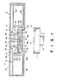
- the magnetic tape cartridge 1 comprises a cartridge casing 3 formed by fastening together upper and lower casing halves 31 and 32 by screws or the like.
- a single reel 2 around which a magnetic tape (not shown) is wound is housed for rotation in the cartridge casing 3.
- the lower casing half 32 is provided with a central opening 32a.
- the magnetic tape cartridge 1 is further provided with a reel stopper means 10 which permits rotation of the reel 2 when the magnetic tape cartridge 1 is being used and restricts rotation of the reel 2 when the magnetic tape cartridge 1 is not being used.
- the reel 2 comprises a reel hub 21 which is a cylindrical member having a closed bottom and around which the magnetic tape is wound, and lower and upper flanges 22 and 23.
- the reel hub 21 and the lower flange 22 are integrally formed by synthetic resin molding.
- the upper flange 23 is bonded to the reel hub 21, for instance, by ultrasonic welding.
- the reel hub 21 is provided with a bottom wall 21a at the lower end portion thereof and a reel gear 24 for rotating the reel 2 is annularly formed on the lower surface of the bottom wall 21a, and annular reel plate 25 which is magnetically attracted by a reel drive means 11 of a recording and reproducing apparatus is mounted on the lower surface of the bottom wall 21a inside the reel gear 24.
- the reel 2 is urged downward by an urging means 5 to be described later.
- the reel drive means 11 is provided with an annular drive gear 13 and a magnet (not shown) disposed on the top surface of a rotary shaft 12.
- the mechanism of the reel stopper means 10 will be described, hereinbelow.
- the reel stopper means 10 comprises a braking member 4 which is movable up and down between a locking position where it is in contact with the reel 2 to restrict rotation of the reel 2 and a releasing position where it is away from the reel 2 to permit rotation of the same, an urging member 5 which urges the braking member 4 toward the locking position, and a releasing member 6 which moves the braking member 4 toward the releasing position.
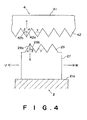
- three through holes 26 are formed in the bottom wall 21a of the reel 2 at regular angular intervals in the circumferential direction to extend through the portion at which the reel gear 24 is formed.
- On the upper surface of the bottom wall 21a there are erected three pairs of (six) engagement projections 27 at regular angular intervals in the circumferential direction among the through holes 26.
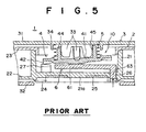
- the upper end of each engagement projection 27 is formed into an engagement gear teeth 29 as shown in Figure 4.
- the through holes 26 may be larger than three in number and the engagement projections 27 may be larger three pairs in number. Further, the upper end of each engagement projection 27 may be formed into a single gear tooth.
- the braking member 4 has a disc portion 41 which is disposed in the reel hub 21 opposed to the bottom wall 21a, and an annular braking gear 42 is formed on the lower surface of the disc portion 41 along the outer peripheral edge thereof.
- the braking gear 42 is adapted to be engaged with the engagement gear 29 on the engagement projections 27.
- the central part of the lower surface of the disc portion 41 is convex downward and forms a sliding portion 41a which is pressed against a sliding portion 61a on the upper surface of a body portion 61 of the releasing member 6 to be described later.
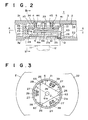
- An outer diameter D of the engagement gear formed by the engagement gear teeth 29 on the engagement projections 27 on the reel 2 ( Figure 3) is larger than an outer diameter d ( Figure 2) of the braking gear 42 on the braking member 4.
- the braking gear 42 and the engagement gear 29 are conical in shape and the height of each tooth is higher at the outer periphery thereof. Accordingly, the braking gear 42 is engaged with the engagement gear teeth 29 at their outer peripheries first.
- each guide member 39 is in the form of a rib having an inclined surface which gradually inclines downward from the upper portion of the inner surface of the reel hub 21 toward the engagement projections 27, and the guide members 39 center the braking gear 42 when the outer periphery of the braking gear 42 is brought into contact with the inclined surfaces.
- each gear tooth of the braking gear 42 of the braking member 4 and each engagement gear tooth 29 on the engagement projection 27 are triangular in cross-section.
- the gear tooth of the braking gear 42 has a first inclined surface 42a which faces against the tape-unwinding direction U and abuts against a first inclined surface 29a of the engagement gear tooth 29 on the engagement projection 27 which faces toward the tape-unwinding direction U, and a second inclined surface 42b which faces against the tape-winding direction W and abuts against a second inclined surface 29b of the engagement gear tooth 29 on the engagement projection 27 which faces toward the tape-winding direction W.
- Each of the gear tooth 42 and the gear tooth 29 is not larger than 90° in apical angle ⁇ , and an interior angle ⁇ between the first inclined surface 42a (or 29a) and a vertical S and an interior angle ⁇ between the second inclined surface 42b (or 29b) and the vertical S are not smaller than 30°. Further, the interior angle ⁇ for the first inclined surface 42a (29a) is not larger than the interior angle ⁇ for the second inclined surface 42b (29b). That is, 60° ⁇ 90°, 30° ⁇ 45°, and 30° ⁇ 60°.
- a projection 44 extends upward from the upper surface of the disc portion 41 of the braking member 4, and a cross-shaped engagement groove 45 is formed in the projection 44 to extend in the vertical direction.
- An engagement projection 33 extending downward from the inner surface of the upper casing half 31 of the cartridge casing 3 is in engagement with the engagement groove 45 of the braking member 4, whereby the braking member 4 is held in the cartridge casing 3 to be movable up and down but not to be rotatable.
- a coiled spring (urging member) 5 is compressed between a portion of the upper surface of the disc portion 41 around the projection 44 and a spring retainer portion 34 formed on the upper casing half 31 around the engagement projection 33, whereby the braking member 4 is urged toward the locking position where the braking gear 42 is engaged with the engagement gear teeth 29 on the engagement projections 27.
- the releasing member 6 is disposed to be movable up and down between the braking member 4 and the bottom wall 21a of the reel hub 21 and comprises the substantially triangular plate-like body portion 61.
- a cylindrical leg portion 63 extends downward from the lower surface of the body portion 61 at each corner thereof.
- the leg portions 63 are passed through the through holes 26 in the bottom wall 21a of the reel 2 to be movable up and down.
- the engagement projections 27 are positioned between the leg portions 63 outside the body portion 61 of the releasing member 6.
- the leg portions 63 may also be rectangular or ellipsoidal in cross-section.
- the releasing member 6 When the releasing member 6 is in its lowermost position shown in Figure 1, the lower ends of the leg portions 63 project downward form the lower surface of the reel 2 through the portion at which the reel gear 24 is formed, and when the drive gear 13 is brought into engagement with the reel gear 24 in response to a chucking action of the reel drive means 11, the leg portions 63 are pushed upward by a predetermined stroke as shown in Figure 2, whereby the braking gear 42 of the braking member 4 is disengaged from the engagement gear teeth 29 of the engagement projections 27 and rotation of the reel 2 is permitted. Since the leg portions 63 are passed through the through holes 26 the releasing member 6 is rotated together with the reel 2.
- the reel 2 is provided with guide members 28 ( Figure 3) which guide the releasing member 6 when the leg portions 63 are inserted into the through holes 26.
- Each of the guide members 28 guides a corner of the body portion 61 of the releasing member 6 and comprises a pair of guide ribs formed on the inner surface of the reel hub 21 to extend in the vertical direction near one of the through holes 26. Reinforcing ribs like the guide ribs are provided on the entire inner surface of the reel hub 21.
- Figure 1 shows a state of the magnetic tape cartridge 1 when it is not being used (e.g., when it is stored).
- the braking member 4, the releasing member 6 and the reel 2 are held in the lower casing half 32 of the cartridge casing 3 under the force of the urging member 5 and the central opening 32a of the lower casing half 32 is closed by the reel 2.
- the releasing member 6 is in its lowermost position where its lower surface is in abutment against the upper surface of the bottom wall 21a of the reel hub 21 and the lower end portions of the leg portions 63 project downward beyond the tips of the teeth of the reel gear 24.
- the braking member 4 is in abutment against the releasing member 6 and in its locking position where the braking gear 42 is in mesh with the engagement gear teeth 29 of the engagement projections 27 on the reel 2, whereby rotation of the reel 2 is restricted and the magnetic tape is prevented from being drawn out.
- the braking member 4 When the braking member 4 is moved downward from the releasing position to the locking position, the braking member 4 is centered by the guide members 39 on the reel 2 so that the braking gear 42 is brought into mesh with the engagement gear teeth 29 with the braking member 4 held horizontal, whereby the braking member 4 is prevented from being inclined in the locking position.
- the braking member 4 When the braking member 4 is subsequently moved upward to the releasing position by the releasing member 6, the braking member 4 is held horizontal up to the releasing position. Accordingly, the phenomenon that the braking member 4 is inclined as shown in Figure 5 can be suppressed, whereby the braking gear 42 is prevented from contacting the engagement gear teeth 29 to generate noise or to obstruct rotation of the reel 2.
- the braking member 4 is automatically centered in the reel hub 2 by the guide members 39 and is incorporated in place in the reel 2, whereby assembly of the magnetic tape cartridge 1 is facilitated.
- the braking member 4 is centered with respect to the reel hub 2 when it is moved from the releasing position to the locking position by virtue of the difference in diameter so that the braking gear 42 is brought into mesh with the engagement gear teeth 29 with the braking member 4 held horizontal, whereby the braking member 4 is prevented from being inclined in the locking position.
- the braking member 4 is moved upward along the first inclined surfaces 42a and 29a since the interior angles ⁇ for the first inclined surfaces 42a and 29a, which are brought into abutment against each other when the reel 2 is rotated in the unwinding direction U, are not smaller than 30°, and the braking gear 42 is disengaged from the engagement gear teeth 29, whereby the reel 2 is rotated in the unwinding direction U to reduce the tension on the magnetic tape, and the magnetic tape can be prevented from being stretched or cut.
- the reel 2 can be anyhow rotated even if the braking member 4 is in the locking position, though the rotation of the reel 2 is restricted. Accordingly, when the magnetic tape is accidentally drawn out from the cartridge casing 3 during storage or the like of the magnetic tape cartridge 1, the magnetic tape can be rewound into the cartridge casing 3.
- the effect of reducing the tension on the magnetic tape can be obtained when the interior angle ⁇ is not smaller than 30°.
- the interior angle ⁇ is larger than 45°, the locking force for preventing rotation of the reel 2 in the unwinding direction becomes too weak. That is, in order to ensure both the effect of reducing the tension on the magnetic tape and the sufficient locking force, it is necessary that an apical angle ⁇ is not larger than 90° and the interior angles ⁇ for the first inclined surfaces 42a and 29a, which are brought into abutment against each other when the reel 2 is rotated in the unwinding direction U, are smaller than the interior angles ⁇ for the second inclined surfaces 42b and 29b which are brought into abutment against each other when the reel 2 is rotated in the winding direction W.
- the height of the gear teeth of the braking gear 42 and that of the engagement gear teeth 29 are set according to the distance between the locking position and the releasing position of the braking member 4. For a given height of the teeth, the number of the teeth is reduced and the one-pitch length is increased as the apical angle ⁇ increases. Accordingly, when the apical angle ⁇ is set not to be larger than 90°, the number of the gear teeth of the braking gear 42 is increased and the one-pitch length is reduced, whereby slack of the magnetic tape or the tension on the magnetic tape can be proper when the braking gear 42 is engaged with the engagement gear teeth 29.
Landscapes
- Unwinding Webs (AREA)
- Storing, Repeated Paying-Out, And Re-Storing Of Elongated Articles (AREA)
- Braking Arrangements (AREA)
- Storage Of Web-Like Or Filamentary Materials (AREA)
Claims (5)
- Magnetbandkassette (1), aufweisend ein um eine Einzelspule (2) geschlungenes Magnetband, ein Kassettengehäuse (3) zum Unterbringen der Spule (2) und eine Spulenanschlageinrichtung (10) zum Verriegeln der Spule (2) oder zum Gestatten der Drehung derselben, wobei die Spulenanschlageinrichtung (10) ein Bremsteil (4) aufweist, das zwischen einer Verriegelungsposition und einer Freigabeposition bewegbar ist, ein Vorspannteil (5) zum Vorspannen des Bremsteils (4) in die Richtung zu der Verriegelungsposition, und ein Freigabeteil (6), das einstückig mit der Spule (2) gedreht wird, zum Bewegen des Bremsteils (4) in Richtung zu der Freigabeposition in Abhängigkeit von einer Spulenspannwirkung einer Spulenantriebseinrichtung (11) eines Bandantriebs, und wobei das Bremsteil (4) mit einem Bremszahnrad (42) versehen ist, das Zahnradzähne aufweist, die vorgesehen sind, um mit zumindest einem Eingriffszahnradzahn (29) eines Eingriffsvorsprungs (27), gebildet an der Spule (2) in Eingriff zu sein, dadurch gekennzeichnet, dass jedes der Zahnradzähne des Bremszahnrades (42) aufweist eine erste geneigte Oberfläche (42a), die in die Richtung zu einer Bandabwicklungsrichtung (U) gerichtet ist und eine zweite geneigte Oberfläche (42b), die in die Richtung zu einer Bandaufwickelrichtung (W) gerichtet ist, wobei ein Innenwinkel (α) zwischen der ersten geneigten Oberfläche (42a) und einer Vertikalen (s) kleiner ist als ein Innenwinkel (β) zwischen der zweiten geneigten Oberfläche (42b) und der Vertikalen (s), und die geneigten Oberflächen (42a, 42b) dazwischen einen spitzen Winkel (γ) bildet, der kleiner als 90° ist.
- Magnetbandkassette (1) nach Anspruch 1, dadurch gekennzeichnet, dass zumindest ein Eingriffszahnradzahn (29) eine erste und eine zweite geneigte Oberfläche (29a, 29b) aufweist, jeweils entsprechend der ersten und der zweiten geneigten Oberfläche (42a, 42b) der Zahnradzähne des Bremszahnrades (42) entsprechen.
- Magnetbandkassette (1) nach Anspruch 1 oder 2, dadurch gekennzeichnet, dass die Spule (2) mit einem Führungsteil (28, 39) zum Zentrieren des Bremsteils (4) in Bezug auf die Spule (2) versehen ist.
- Magnetbandkassette (1) nach Anspruch 3, dadurch gekennzeichnet, dass das Führungsteil (39) Führungsrippen auf einer Innenoberfläche einer Spulennabe (21) an zumindest drei Stellen aufweist, wobei jede Führungsrippe eine geneigte Oberfläche aufweist, die von einem oberen Abschnitt der Innenoberfläche der Spulennabe (21) in Richtung zu einer Mitte der Spule (2) geneigt ist.
- Magnetbandkassette (1) nach zumindest einem der Ansprüche 1 bis 4, dadurch gekennzeichnet, dass ein Außendurchmesser (D) eines Eingriffszahnrades, das zumindest einen Eingriffszahnradzahn (29) aufweist, größer als ein Außendurchmesser (d) des Bremszahnrades (42) ist.
Priority Applications (1)
| Application Number | Priority Date | Filing Date | Title |
|---|---|---|---|
| EP04020872A EP1492112B1 (de) | 1999-11-08 | 2000-11-08 | Magnetbandkassette |
Applications Claiming Priority (4)
| Application Number | Priority Date | Filing Date | Title |
|---|---|---|---|
| JP31716699 | 1999-11-08 | ||
| JP31716699 | 1999-11-08 | ||
| JP31846499 | 1999-11-09 | ||
| JP31846499 | 1999-11-09 |
Related Child Applications (1)
| Application Number | Title | Priority Date | Filing Date |
|---|---|---|---|
| EP04020872A Division EP1492112B1 (de) | 1999-11-08 | 2000-11-08 | Magnetbandkassette |
Publications (3)
| Publication Number | Publication Date |
|---|---|
| EP1098320A2 EP1098320A2 (de) | 2001-05-09 |
| EP1098320A3 EP1098320A3 (de) | 2001-09-12 |
| EP1098320B1 true EP1098320B1 (de) | 2007-04-04 |
Family
ID=26568944
Family Applications (2)
| Application Number | Title | Priority Date | Filing Date |
|---|---|---|---|
| EP00124448A Expired - Lifetime EP1098320B1 (de) | 1999-11-08 | 2000-11-08 | Magnetbandkassette |
| EP04020872A Expired - Lifetime EP1492112B1 (de) | 1999-11-08 | 2000-11-08 | Magnetbandkassette |
Family Applications After (1)
| Application Number | Title | Priority Date | Filing Date |
|---|---|---|---|
| EP04020872A Expired - Lifetime EP1492112B1 (de) | 1999-11-08 | 2000-11-08 | Magnetbandkassette |
Country Status (4)
| Country | Link |
|---|---|
| US (1) | US6462905B1 (de) |
| EP (2) | EP1098320B1 (de) |
| CN (1) | CN1179359C (de) |
| DE (2) | DE60034202T2 (de) |
Families Citing this family (15)
| Publication number | Priority date | Publication date | Assignee | Title |
|---|---|---|---|---|
| DE19930802A1 (de) * | 1999-07-03 | 2001-01-04 | Emtec Magnetics Gmbh | Magnetbandkassette, insbesondere eine Einspulenkassette für die Datenverarbeitung mit mehrteiligem Bremssystem |
| CN1321420C (zh) * | 1999-07-09 | 2007-06-13 | 富士胶片株式会社 | 盒式磁带 |
| DE60128978T2 (de) | 2000-04-05 | 2007-10-18 | Fujifilm Corp. | Magnetbandkassette |
| DE20021132U1 (de) * | 2000-12-13 | 2001-04-19 | Emtec Magnetics Gmbh | Transportsicherungselement für Datenspeicherkassetten, Datenspeicherkassettenstapel mit Transportsicherungselementen |
| JP2002343058A (ja) * | 2001-05-18 | 2002-11-29 | Fuji Photo Film Co Ltd | 磁気テープカートリッジ |
| JP4146624B2 (ja) * | 2001-05-28 | 2008-09-10 | 富士フイルム株式会社 | 磁気テープカートリッジのリーダピン脱着力測定器 |
| JP2003085930A (ja) * | 2001-05-29 | 2003-03-20 | Fuji Photo Film Co Ltd | 磁気テープカートリッジ |
| JP2003109354A (ja) * | 2001-06-25 | 2003-04-11 | Fuji Photo Film Co Ltd | 磁気テープカートリッジ |
| JP3492662B2 (ja) * | 2001-10-19 | 2004-02-03 | Necパーソナルプロダクツ株式会社 | 可動リーダピンホルダを備えたテープカートリッジ |
| JP2004118884A (ja) * | 2002-09-24 | 2004-04-15 | Fuji Photo Film Co Ltd | 記録テープカートリッジ |
| JP2004199808A (ja) * | 2002-12-19 | 2004-07-15 | Fuji Photo Film Co Ltd | 記録テープカートリッジ |
| US7066421B2 (en) * | 2003-12-10 | 2006-06-27 | Fuji Photo Film Co., Ltd. | Recording tape cartridge |
| US7290734B2 (en) * | 2003-12-22 | 2007-11-06 | Tdk Corporation | Tape reel and information recording medium |
| JP4161934B2 (ja) * | 2004-04-15 | 2008-10-08 | ソニー株式会社 | 磁気テープカートリッジ |
| JP4593431B2 (ja) * | 2005-10-11 | 2010-12-08 | 富士フイルム株式会社 | 記録テープカートリッジ |
Family Cites Families (10)
| Publication number | Priority date | Publication date | Assignee | Title |
|---|---|---|---|---|
| EP0284687A3 (de) * | 1987-03-31 | 1990-02-07 | Shape Inc. | Bandkassette |
| US5366173A (en) * | 1993-03-01 | 1994-11-22 | Storage Technology Corporation | Tape cartridge reel brake release technique |
| DE19681617T1 (de) * | 1995-10-26 | 1998-10-08 | Imation Corp | Struktur zum Beschränken des Randeinknickens bei einer unregelmäßig gewickelten Kassette |
| US6344944B2 (en) * | 1997-06-03 | 2002-02-05 | Quantum Corporation | Mini-cartridge adapter for adapting a mini-cartridge to an industry standard tape cartridge format |
| US6113020A (en) * | 1997-07-02 | 2000-09-05 | Seagate Technology, Inc. | Reel lock and coupling engagement mechanisms for a cartridge |
| JP3614634B2 (ja) | 1997-12-25 | 2005-01-26 | 富士写真フイルム株式会社 | 磁気テープカートリッジ |
| US5901916A (en) * | 1998-03-02 | 1999-05-11 | Hewlett-Packard Company | Tape cartridge reel lock |
| US6680818B1 (en) * | 1998-06-08 | 2004-01-20 | Fuji Photo Film Co., Ltd. | Magnetic tape cartridge for housing a reel |
| US6452748B1 (en) * | 1999-05-21 | 2002-09-17 | Tdk Corporation | Tape cartridge with matched brake lock and brake release plate |
| US6411466B1 (en) * | 1999-05-25 | 2002-06-25 | Tdk Corporation | Tape cartridge |
-
2000
- 2000-11-08 DE DE60034202T patent/DE60034202T2/de not_active Expired - Lifetime
- 2000-11-08 EP EP00124448A patent/EP1098320B1/de not_active Expired - Lifetime
- 2000-11-08 EP EP04020872A patent/EP1492112B1/de not_active Expired - Lifetime
- 2000-11-08 DE DE60038637T patent/DE60038637T2/de not_active Expired - Lifetime
- 2000-11-08 US US09/707,774 patent/US6462905B1/en not_active Expired - Lifetime
- 2000-11-08 CN CNB001334786A patent/CN1179359C/zh not_active Expired - Lifetime
Also Published As
| Publication number | Publication date |
|---|---|
| CN1324077A (zh) | 2001-11-28 |
| DE60034202D1 (de) | 2007-05-16 |
| EP1098320A3 (de) | 2001-09-12 |
| DE60038637D1 (de) | 2008-05-29 |
| EP1098320A2 (de) | 2001-05-09 |
| EP1492112B1 (de) | 2008-04-16 |
| EP1492112A3 (de) | 2006-02-08 |
| DE60038637T2 (de) | 2009-05-14 |
| US6462905B1 (en) | 2002-10-08 |
| EP1492112A2 (de) | 2004-12-29 |
| DE60034202T2 (de) | 2007-07-12 |
| CN1179359C (zh) | 2004-12-08 |
Similar Documents
| Publication | Publication Date | Title |
|---|---|---|
| EP1098320B1 (de) | Magnetbandkassette | |
| US7350732B2 (en) | Cartridge case and information recording medium | |
| US5857634A (en) | Take-up reel lock | |
| JP4424897B2 (ja) | 記録テープカートリッジ | |
| JP5634716B2 (ja) | リール及び記録テープカートリッジ | |
| US7350731B2 (en) | Recording tape cartridge | |
| JP4837450B2 (ja) | 記録テープカートリッジ | |
| US7360291B2 (en) | Method of manufacturing a recording tape cartridge | |
| JP3992695B2 (ja) | カートリッジケースおよび情報記録媒体 | |
| JP2004199808A (ja) | 記録テープカートリッジ | |
| US7175124B2 (en) | Recording tape cartridge | |
| US7407126B2 (en) | Recording tape cartridge | |
| JP4532041B2 (ja) | 磁気テープカートリッジ | |
| JP2001202744A (ja) | 磁気テープカートリッジ | |
| JP5026453B2 (ja) | リール及び記録テープカートリッジ | |
| EP0974974B1 (de) | Einzelspulenbandkassette mit Brems- und Schutzmechanismus | |
| JP2004118884A (ja) | 記録テープカートリッジ | |
| JP2002083481A (ja) | 磁気テープカートリッジ | |
| JP2000048525A (ja) | 磁気テープカートリッジ | |
| JP5127958B2 (ja) | リール | |
| JP2007328835A (ja) | 記録テープカートリッジ | |
| JP2008004265A (ja) | 磁気テープカートリッジ | |
| JP2004192734A (ja) | 記録テープカートリッジ | |
| JPH06111526A (ja) | ダストドアのテープリールロック | |
| JP2004127357A (ja) | 記録テープカートリッジ |
Legal Events
| Date | Code | Title | Description |
|---|---|---|---|
| PUAI | Public reference made under article 153(3) epc to a published international application that has entered the european phase |
Free format text: ORIGINAL CODE: 0009012 |
|
| AK | Designated contracting states |
Kind code of ref document: A2 Designated state(s): AT BE CH CY DE DK ES FI FR GB GR IE IT LI LU MC NL PT SE TR Kind code of ref document: A2 Designated state(s): DE FR GB |
|
| AX | Request for extension of the european patent |
Free format text: AL;LT;LV;MK;RO;SI |
|
| PUAL | Search report despatched |
Free format text: ORIGINAL CODE: 0009013 |
|
| AK | Designated contracting states |
Kind code of ref document: A3 Designated state(s): AT BE CH CY DE DK ES FI FR GB GR IE IT LI LU MC NL PT SE TR |
|
| AX | Request for extension of the european patent |
Free format text: AL;LT;LV;MK;RO;SI |
|
| 17P | Request for examination filed |
Effective date: 20011016 |
|
| AKX | Designation fees paid |
Free format text: DE FR GB |
|
| 17Q | First examination report despatched |
Effective date: 20030819 |
|
| GRAP | Despatch of communication of intention to grant a patent |
Free format text: ORIGINAL CODE: EPIDOSNIGR1 |
|
| GRAS | Grant fee paid |
Free format text: ORIGINAL CODE: EPIDOSNIGR3 |
|
| GRAA | (expected) grant |
Free format text: ORIGINAL CODE: 0009210 |
|
| RAP1 | Party data changed (applicant data changed or rights of an application transferred) |
Owner name: FUJIFILM CORPORATION |
|
| AK | Designated contracting states |
Kind code of ref document: B1 Designated state(s): DE FR GB |
|
| REG | Reference to a national code |
Ref country code: GB Ref legal event code: FG4D |
|
| REF | Corresponds to: |
Ref document number: 60034202 Country of ref document: DE Date of ref document: 20070516 Kind code of ref document: P |
|
| ET | Fr: translation filed | ||
| PLBE | No opposition filed within time limit |
Free format text: ORIGINAL CODE: 0009261 |
|
| STAA | Information on the status of an ep patent application or granted ep patent |
Free format text: STATUS: NO OPPOSITION FILED WITHIN TIME LIMIT |
|
| 26N | No opposition filed |
Effective date: 20080107 |
|
| REG | Reference to a national code |
Ref country code: FR Ref legal event code: PLFP Year of fee payment: 16 |
|
| REG | Reference to a national code |
Ref country code: FR Ref legal event code: PLFP Year of fee payment: 17 |
|
| REG | Reference to a national code |
Ref country code: FR Ref legal event code: PLFP Year of fee payment: 18 |
|
| REG | Reference to a national code |
Ref country code: FR Ref legal event code: PLFP Year of fee payment: 19 |
|
| PGFP | Annual fee paid to national office [announced via postgrant information from national office to epo] |
Ref country code: DE Payment date: 20191029 Year of fee payment: 20 |
|
| PGFP | Annual fee paid to national office [announced via postgrant information from national office to epo] |
Ref country code: FR Payment date: 20191015 Year of fee payment: 20 |
|
| PGFP | Annual fee paid to national office [announced via postgrant information from national office to epo] |
Ref country code: GB Payment date: 20191107 Year of fee payment: 20 |
|
| REG | Reference to a national code |
Ref country code: DE Ref legal event code: R071 Ref document number: 60034202 Country of ref document: DE |
|
| REG | Reference to a national code |
Ref country code: GB Ref legal event code: PE20 Expiry date: 20201107 |
|
| PG25 | Lapsed in a contracting state [announced via postgrant information from national office to epo] |
Ref country code: GB Free format text: LAPSE BECAUSE OF EXPIRATION OF PROTECTION Effective date: 20201107 |