EP0974974B1 - Einzelspulenbandkassette mit Brems- und Schutzmechanismus - Google Patents
Einzelspulenbandkassette mit Brems- und Schutzmechanismus Download PDFInfo
- Publication number
- EP0974974B1 EP0974974B1 EP99305725A EP99305725A EP0974974B1 EP 0974974 B1 EP0974974 B1 EP 0974974B1 EP 99305725 A EP99305725 A EP 99305725A EP 99305725 A EP99305725 A EP 99305725A EP 0974974 B1 EP0974974 B1 EP 0974974B1
- Authority
- EP
- European Patent Office
- Prior art keywords
- tape
- reel
- band
- housing
- cartridge
- Prior art date
- Legal status (The legal status is an assumption and is not a legal conclusion. Google has not performed a legal analysis and makes no representation as to the accuracy of the status listed.)
- Expired - Lifetime
Links
- 230000007246 mechanism Effects 0.000 title claims description 32
- 239000000463 material Substances 0.000 claims description 9
- 230000008859 change Effects 0.000 claims description 6
- 230000001419 dependent effect Effects 0.000 claims 2
- 230000006870 function Effects 0.000 description 11
- 230000001681 protective effect Effects 0.000 description 8
- 238000004804 winding Methods 0.000 description 7
- 230000006378 damage Effects 0.000 description 6
- 238000011109 contamination Methods 0.000 description 5
- 238000000034 method Methods 0.000 description 3
- 230000004048 modification Effects 0.000 description 3
- 238000012986 modification Methods 0.000 description 3
- 239000013618 particulate matter Substances 0.000 description 3
- 230000008901 benefit Effects 0.000 description 2
- 238000013500 data storage Methods 0.000 description 2
- 239000000428 dust Substances 0.000 description 2
- 230000007613 environmental effect Effects 0.000 description 2
- 238000004519 manufacturing process Methods 0.000 description 2
- 230000036961 partial effect Effects 0.000 description 2
- 230000008569 process Effects 0.000 description 2
- 230000002441 reversible effect Effects 0.000 description 2
- 230000004888 barrier function Effects 0.000 description 1
- 238000004364 calculation method Methods 0.000 description 1
- 239000011248 coating agent Substances 0.000 description 1
- 238000000576 coating method Methods 0.000 description 1
- 230000006835 compression Effects 0.000 description 1
- 238000007906 compression Methods 0.000 description 1
- 230000000694 effects Effects 0.000 description 1
- 230000008030 elimination Effects 0.000 description 1
- 238000003379 elimination reaction Methods 0.000 description 1
- 230000006353 environmental stress Effects 0.000 description 1
- -1 fingerprints Substances 0.000 description 1
- 230000006872 improvement Effects 0.000 description 1
- 230000002401 inhibitory effect Effects 0.000 description 1
- 229920000642 polymer Polymers 0.000 description 1
- 230000009467 reduction Effects 0.000 description 1
- 230000004044 response Effects 0.000 description 1
- 239000000779 smoke Substances 0.000 description 1
Images


Classifications
-
- G—PHYSICS
- G11—INFORMATION STORAGE
- G11B—INFORMATION STORAGE BASED ON RELATIVE MOVEMENT BETWEEN RECORD CARRIER AND TRANSDUCER
- G11B23/00—Record carriers not specific to the method of recording or reproducing; Accessories, e.g. containers, specially adapted for co-operation with the recording or reproducing apparatus ; Intermediate mediums; Apparatus or processes specially adapted for their manufacture
- G11B23/02—Containers; Storing means both adapted to cooperate with the recording or reproducing means
- G11B23/04—Magazines; Cassettes for webs or filaments
- G11B23/041—Details
- G11B23/043—Brakes for tapes or tape reels
-
- G—PHYSICS
- G11—INFORMATION STORAGE
- G11B—INFORMATION STORAGE BASED ON RELATIVE MOVEMENT BETWEEN RECORD CARRIER AND TRANSDUCER
- G11B23/00—Record carriers not specific to the method of recording or reproducing; Accessories, e.g. containers, specially adapted for co-operation with the recording or reproducing apparatus ; Intermediate mediums; Apparatus or processes specially adapted for their manufacture
- G11B23/02—Containers; Storing means both adapted to cooperate with the recording or reproducing means
- G11B23/04—Magazines; Cassettes for webs or filaments
- G11B23/08—Magazines; Cassettes for webs or filaments for housing webs or filaments having two distinct ends
- G11B23/107—Magazines; Cassettes for webs or filaments for housing webs or filaments having two distinct ends using one reel or core, one end of the record carrier coming out of the magazine or cassette
Definitions
- This invention relates to magnetic tape drives in general, and in particular to single reel recording tape cartridges.
- a widely used medium for storing data is recording tape, which is typically a polymer tape with a magnetic coating.
- recording tape is typically a polymer tape with a magnetic coating.
- tape cartridges One of the most popular formats of use for the storage of data on tape. Tape cartridges are generally smaller, simpler and less expensive than reel-to-reel tape systems.
- Two widely used formats of tape cartridges are the two-reel cartridge, which is typically in a quarter-inch tape format, and the single, supply-reel cartridge, generally a half-inch tape format cartridge.
- the single, supply-reel or half-inch cartridge is able to store much more data than the quarter inch cartridge.
- the free end of the tape in the cartridge is attached to a leader block.
- the leader block is fashioned to act as a barrier or door when the cartridge is not in use, and thereby greatly reduce exposure of the cartridge to potential sources of harm such as dust, particulate matter contamination and other forms of environmental stress or damage.
- the leader block's function is to provide a structure to allow the tape to be withdrawn from the cartridge, into the tape drive for data recording or retrieval.
- the take-up reel or spool is built into the tape drive along with an automatic tape threading mechanism.
- the automatic tape threading mechanism includes a means for capturing the leader block, typically the capture is by a tape threading pin, and then the mechanism appropriately threads the leader block and tape in the tape drive.
- the recording of data onto the tape is generally referred to as "writing” to the tape and the retrieval of information already written or stored on the tape is referred to as “reading” from the tape.
- the part of the tape system responsible for these activities is generally referred to as the read/write head.
- the tape drive that performs the read/write operations is also referred to as a tape "transport.”
- the standard tape transport or drive accepts the tape cartridge into an elevator assembly.
- a threading mechanism grabs the leader block and pulls it free from the cartridge.
- the leader block is then used to thread the tape through a path which includes a series of guide posts, across the longitudinal read/write head, and into a slot in the take-up reel.
- the tape from the cartridge can be driven across the read/write head(s) for data transfer operations and wound onto the take-up reel.
- the take-up reel is typically configured to allow the positioning of the leader block into the hub of the take-up reel in a manner that, ideally, allows the tape to wind smoothly onto the take-up reel.
- the leader block is captured by a threading pin attached to a threading or threader arm assembly. The threading arm then pulls the leader block in a counter-clockwise direction through the tape path and inserts the leader block into the hub of the take-up reel.
- the leader block spins around the threading pin, as the pin and the take-up reel have the same axis of rotation in this configuration.
- the leader block forms a part of the outer circumference of the take-up reel and thus, the magnetic tape winding surface.
- the leader block and take-up reel are fabricated with a degree of precision so that when the leader block is inserted into the slot in the take-up reel, the slot is closed by the end of the leader block so that a relatively smooth surface is created on the hub of the take-up reel for winding the tape on the hub.
- the tape cartridge, or housing and all of the components are designed and manufactured to promote the best possible storage and retrieval of data on the tape.
- One important goal in the design and manufacture of the components is to have the tape wind smoothly through the drive and onto and off of both the supply reel and the take-up reel.
- Another important goal in the design and manufacture of the tape cartridge is to protect the tape cartridge and data stored on the tape from physical damage, such as environmental contamination. Examples of sources of contamination include smoke, dust, fingerprints, and other particulate matter.
- sources of contamination include smoke, dust, fingerprints, and other particulate matter.
- Any misalignment of the magnetic tape within the system can result in a non-uniform tape winding surface which causes undesirable irregularities in the magnetic tape as it is wound or unwound from either reel.
- Such misalignments can garble data and operations, causing errors in either or both the writing of data to the tape and reading of data from the tape.
- Improvements in the functioning of the tape storage and retrieval system are constantly sought to decrease sources of error and failure in data storage and retrieval. Whenever data is transmitted and wherever it is stored, it is vulnerable to many different forces and conditions that can physically distort the record, changing the character of the data. Any source of error is problematical to the accurate and successful recording and retrieval of data to and from the tape. Irretrievable data can be catastrophic at worst and is always undesirable. The consequences can be devastating; for example, as little as a single wrong data bit can change the meaning of an entire sequence of bits, perhaps throwing off a complex mathematical calculation or causing a computer to misinterpret a command. The sources of risk for error and failure are under constant scrutiny for reduction and elimination in the industry. A combination of strategies may be best to safeguard the data from the inevitable assault of errors.
- a place in the system where problems can occur or develop is the supply reel, in the tape cartridge.
- the cartridge When the cartridge is not in use in a tape drive, it is possible in some cartridges for the tape to lose tension and become partially unwound from the reel.
- the tape When the tape is loose and unwound, it is possible for the tape to loop back on itself.
- the tape can be damaged as a result of the loose wraps and misalignments, for example, the recording side of the tape coming in contact with itself and causing damage.
- Loose or misaligned tape on the reel can also be damaged by sharp creases being put in the tape, if the looped-back sections inadvertently become trapped and rewound tightly and under tension on the supply reel or through snapping and possibly breaking the tape when tension is restored to the tape in the cartridge.
- the tape in the cartridge can also be damage by contamination and/or particulate matter, as well as loose or unwound tape in combination with environmental contamination.
- one solution has been to add additional structures to the cartridge. For example, spring-biased catches, that grab either an added brake structure, or the drive gears that are integrated on the reel, for engagement with the torque motor when in the tape drive, have been utilized.
- a tape cartridge comprising a housing having an opening therein, a tape supply reel rotatably disposed within the housing, a web of magnetic tape wound on the tape reel and having a free end disposed proximate the housing opening, and a tape reel braking mechanism.
- the braking mechanism comprises a band that is anchored at a fulcrum point with respect to the reel, for movement between a braking position, in which the band contacts and compresses the tape wound on the tape reel, and a free position, in which there is no compression on the tape reel from the band.
- the band extends around approximately half of the circumference of the reel.
- the invention comprises, in general terms, a tape cartridge for use with an operatively compatible tape drive having a tape reeling mechanism, the cartridge comprising a housing having with an opening therein, a tape-supply reel within the housing, magnetic tape wound on the reel and having a free end proximate the housing opening, a tape reel braking and protection mechanism which comprises a band substantially surrounding a marginal edge of the tape reel; and the band being anchored with respect to the reel at least one fulcrum point for the band to allow variation of an effective radius of the band and configured to interact with a radius controller mechanism for varying the effective radius of the band.
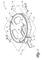
- the tape cartridge of the present invention generally includes at least a housing 20, a tape supply reel 30, with magnetic tape 40 and tape reel braking and protection mechanism or band 50.
- Housing 20 of cartridge 10 is generally rectangular in shape and generally a box-like structure, adapted to enclose a single reel of tape.
- Housing 20 includes a top section 22, which is parallel to a bottom section 24, with top 22 and bottom 24 being joined by a plurality of sidewalls 26. Sidewalls 26 are perpendicular to top 22 and bottom 24.
- Housing 20 may be composed of any appropriate material, such that the outside of housing 20 will not change shape when band 50 changes shape. Housing 20 may be opaque or transparent.
- Housing 20 further includes an access window 28. Access window 28 may be located in any appropriate location along a sidewall 26 of housing 20. For example, window 28 may be located in approximately the center of a sidewall 26 or near a corner, where two sidewalls 26 meet.
- window 28 only needs to be compatible with any particular tape drive unit that cartridge 10 is intended to be used with.
- housing 20 is generally rectangular in shape, a shortened, angled additional sidewall is optionally included, as the location of access window 28.
- housing 20 is still substantially rectangular with the fifth side appearing as a notched or flattened corner, on one of the corners of the rectangle.
- Access window 28 permits the entry and exit of a leader block through window 28.
- Tape supply reel 30 has a top flange 32, bottom flange 34, and tape-winding hub 36.
- Hub 36 has a radial, tape-winding surface, and a top 36T, and bottom 36B.
- Top flange 32 is substantially disk-shaped and has a top surface 32T, a bottom surface 32B and an outside marginal or circumferential edge 32E.
- Top flange 32 is attached to hub 36 concentrically, with bottom surface 32B of top flange 32 being attached to top surface 36T of hub 36.
- Bottom flange 34 is of like dimension as top flange 32.
- Bottom flange 34 has a top surface 34T, bottom surface 34B and outside marginal or circumferential edge 34E.
- Bottom flange 34 is also attached to hub 36 in an analogous relationship to that of top flange 32, with the distinction that top surface 34T of bottom flange 34 is attached to bottom surface 36B of hub 36.
- a length or web of magnetic tape 40 is wound on to hub 36 of supply reel 30.
- tape 40 is wound on to reel 30 in a counterclockwise direction.
- a fixed end (not shown) of tape 40 is attached by any appropriate means to hub 36.
- Tape 40 is disposed in wraps around hub 36, as is well known to one skilled in the art.
- Band 50 is located between tape supply reel 30 and the inside of housing 20.
- Band 50 comprises a first end 52, a second end 54, inner surface 56 and outer surface 58.
- An opening 60 may be created between, and defined by the space between first end 52 and second end 54.
- Band 50 is further comprised of at least one fulcrum point.
- Band 50 is configured to interact with a radius controller mechanism 62.
- Outer surface 58 of band 50 is oriented to face the inside of the sidewalls 26 of housing 20.
- Inner surface 56 of band 50 is oriented with inner surface 56 facing reel 30, rather than a sidewall 26 of housing 20.
- Inner surface 56 is configured and dimensioned to be in contact with both marginal edge 32E of top flange 32 and marginal edge 34E of bottom flange 34, when band 50 is in an inactive or braking position, as shown in Figs. 2a and 2b.
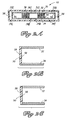
- Outer surface 58 of band 50 may be circular in shape and symmetrical with the shape of reel 30 and inside surface 56, as shown in Figs. 3 and 4 or outer surface 58 may have a different shape, for example outer surface 58 might approximately conform to the shape of the inside of housing 20, as shown in Fig. 5.
- Band 50 functions to protect recording tape 40.
- Band 50 also functions as a braking mechanism and immobilizes reel 30 in a stationary position, thereby inhibiting tape 40 from unwinding or becoming loosely wound on reel 30.
- An important feature of cartridge 10 is that contact caused by band 50 is purposefully made with both top flange 32 and bottom flange 34 of reel 30 when band 50 is in it's inactive or protective and braking position inside housing 20.
- band 50 may also provide handling structure and support for functional elements of cartridge 10 including, but not limited to, a write-protect switch, a door, a leader block parking space and other functional elements.
- band 50 originates in an inactive, or protective and braking position in cartridge 10.
- band 50 In the inactive or protective and braking position, band 50 has a first effective radius R1 that is effectively the same as the radius of reel 30.
- the inside surface 56 of band 50 would be in contact with both circumferential edge 32E of top flange 32 and circumferential edge 34E of bottom flange 34.
- band 50 when band 50 is in the inactive position with effective radius R1, band 50 functions to protect recording tape 40 and also functions as a braking mechanism, permitting reel 30 to be immobilized in a stationary position.
- band 50 In the released or open position, band 50 has a second effective radius R2 that is greater than the radius of reel 30, thereby allowing reel 30 to rotate freely to the extent necessary for the use of tape 40 and cartridge 10.
- R2 second effective radius
- Band 50 has at least one fulcrum point and preferably two.
- band 50 may be made from a comparatively deformable material and attached to housing 20 at two fulcrum points.
- the fulcrum points result from the attachment of band 50 to housing 20 by first rib 68 and second rib 70, as shown in Figs. 3A and 3B.
- band 50 is made from a comparatively rigid material and attached to housing 20 at the fulcrum points.
- the fulcrum points result from the attachment of band 50 to housing 20 by first anchor point 72 and second anchor point 74, as shown in Figs. 1, 4A and 4B.
- housing 20 is made from a suitably rigid material, such that the outside of housing 20 is not deformed and does not change shape in response to the change of effective radius of band 50.
- Band 50 would function and operate, in use, in the same manner in any embodiment.
- First end 52 and second end 54 of band 50 are moved apart by radius controller mechanism 62.
- Radius controller mechanism 62 moves apart first end 52 and second end 54, changing the effective radius of band 50 from R1 to R2.
- Radius controller mechanism 62 may be a separate device that performs this operation or it may be integral with the leader block in housing 20 or may be resident in the tape drive unit that tape cartridge 10 is inserted into.
- the radius controller device could be any appropriate device, such as, but not limited to, a cam, gear, lever, series of mechanical linkages, other appropriate mechanical devices or magnetic or electro-magnetic device to move first end 52 and second end 54 apart. After first end 52 and second end 54 have been spaced apart by radius controller mechanism 62, then cartridge 10 functions in the typical fashion, as described elsewhere in this description.
- band 50 may be returned to the inactive or protective and braking position, with the effective radius R1.
- Band 50 is returned to the inactive position by removing radius controller mechanism 62 from between first end 52 and second end 54. With the removal of radius controller mechanism 62 band 50 returns to the inactive position and has effective radius R1, which is approximately the same as the effective radius of reel 30.
- band 50 is in the inactive position inside surface 56 of band 50 is in braking and protective contact with the marginal edges 32E and 34E of top rim 32 and bottom flange 34, respectively.
- Band 50 has an effective radius of R1 when it is in the inactive or protective and braking position and the R1 radius is effectively the same as the radius of reel 30.
- band 50 In the open or released position, band 50 has second effective radius R2 that is greater than the radius of reel 30 and which allows reel 30 to rotate appropriate for use of tape 40 and cartridge 10.
- band 50 stays concentric to reel 30 in both the open position, having the effective radius R2 and the inactive position, having the effective radius R1, of band 50. Additionally when band 50 is in the open position, with effective radius R2, the outside of housing 20 does not significantly deform or change shape.
- tape cartridge 10 The typical function of tape cartridge 10 is well known to one skilled in the art and only briefly described herein.
- typically tape cartridge 10 is inserted into a tape drive and a leader block retriever would captively engage with the leader block. After the engagement, the leader block would then be pulled from housing 20, through access window 28, along with attached data tape 40, through an appropriate path to thread data tape 40 in the tape drive unit for read/write operations.
- tape 40 winds on to a take-up reel in the tape drive unit, as is well known in the art. As the take-up reel continues rotating in the same winding-on direction, data tape 40 is then wound smoothly on the take-up reel. As more and more wraps of data tape 40 continue to wrap on top of each other, the storage space on the take-up reel will become filled with tape 40.
- band 50 would still function to protect and hold reel 30 in a stationary position.
- band inside surface 56, flanges 32 or 34 of reel 30, or any combination of those structures could be manufactured from materials which further augment the braking and protective relationship of band 50 and reel 30, when they are in contact with each other.
- One such example would be to use materials for the above mentioned structures with a coefficient of friction that improves the braking and protective relationship, as described above and shown in Fig. 2C.
- reel 30 is secured by band 50 in a stationary position in housing 20 with tape 40 under mild tension.
- the present invention permits alternative way of protecting tape 40 and its associated data read/write functions in cartridge 10.
- this invention can be used with a wide variety of threading and/or tape supply mechanisms.
- the invention can be used with a variety of threading arm and threading pin combinations in conjunction with take-up reel 30 and housing of the tape drive unit.
- band 50 may be appropriately manipulated to vary the effective radius of band 50 within housing 20.
Claims (10)
- Eine Bandkassette (10) zur Verwendung mit einem wirksam kompatiblen Bandlaufwerk mit einem Bandspulmechanismus, die folgende Merkmale aufweist:ein Gehäuse (20) mit einer Öffnung (28) darin;eine Bandzuführspule (30), die drehbar innerhalb des Gehäuses (10) angeordnet ist;eine Bahn eines Magnetbandes (40), gewickelt auf die Bandspule (30) und mit einem freien Ende (42), das in der Nähe der Gehäuseöffnung (28) angeordnet ist; undeinen Bandspulen-Brems- und -Schutz-Mechanismus, der folgende Merkmale aufweist:eine Bande (50), die im Wesentlichen eine Randkante (32E, 34E) der Bandspule (30) umgibt; undwobei die Bande (50) im Hinblick auf die Spule (30) an zumindest einem Drehpunkt für die Bande (50) verankert ist, um eine Variation eines effektiven Radius (R1, R2) der Bande (50) zu ermöglichen, und konfiguriert ist, um mit einem Radiussteuermechanismus (62) in Wechselwirkung zu treten, zum Variieren des effektiven Radius (R1, R2) der Bande (50).
- Die Bandkassette (10) gemäß Anspruch 1, bei der die Öffnung (28) in einer Ecke des Gehäuses (20) ist.
- Die Bandkassette gemäß Anspruch 1 oder Anspruch 2, bei der die Bandzuführspule (30) einen oberen Flansch (32), einen unteren Flansch (34) und eine mittlere Nabe (36) aufweist.
- Die Bandkassette (10) gemäß Anspruch 3, bei der
das Gehäuse (20) eine Innenseite und eine Außenseite aufweist;
wobei die Bande (50) verankert ist, um konzentrisch auf der Spule (30) zu bleiben; und
wobei die Außenseite des Gehäuses (20) ihre Form nicht aus der Variation des effektiven Radius (R1, R2) der Bande (50) ändert. - Die Bandkassette (10) gemäß einem der vorhergehenden Ansprüche, die ferner einen Führungsblock aufweist.
- Die Bandkassette gemäß Anspruch 3 und gemäß jedem davon abhängigen Anspruch, bei der zumindest einer der Bandzuführspulenflansche (32, 34) konfiguriert ist zum lösbaren Verriegeln mit dem Bandspulen-Brems- und - Schutz-Mechanismus.
- Die Bandkassette gemäß einem der vorhergehenden Ansprüche, bei der der Bandspulen-Brems- und -Schutz-Mechanismus aus einem deformierbaren Material gebildet ist.
- Die Bandkassette gemäß einem der Ansprüche 1 bis 6, bei der der Bandspulen-Brems-Schutz-Mechanismus aus einem starren Material gebildet ist.
- Die Bandkassette gemäß Anspruch 3 und jeglichem davon abhängigen Anspruch, bei der zumindest ein Flansch (32, 34) der Zuführspule (30) eine Kante mit einem hohen Reibungskoeffizienten aufweist.
- Die Bandkassette gemäß einem der vorhergehenden Ansprüche, bei der der Bandspulen-Brems- und -Schutz-Mechanismus aus einem Material mit einem hohen Reibungskoeffizienten hergestellt ist.
Applications Claiming Priority (2)
| Application Number | Priority Date | Filing Date | Title |
|---|---|---|---|
| US09/121,764 US6057994A (en) | 1998-07-23 | 1998-07-23 | Single reel tape cartridge with braking and protection mechanism |
| US121764 | 1998-07-23 |
Publications (3)
| Publication Number | Publication Date |
|---|---|
| EP0974974A2 EP0974974A2 (de) | 2000-01-26 |
| EP0974974A3 EP0974974A3 (de) | 2000-07-19 |
| EP0974974B1 true EP0974974B1 (de) | 2006-04-26 |
Family
ID=22398648
Family Applications (1)
| Application Number | Title | Priority Date | Filing Date |
|---|---|---|---|
| EP99305725A Expired - Lifetime EP0974974B1 (de) | 1998-07-23 | 1999-07-20 | Einzelspulenbandkassette mit Brems- und Schutzmechanismus |
Country Status (4)
| Country | Link |
|---|---|
| US (1) | US6057994A (de) |
| EP (1) | EP0974974B1 (de) |
| JP (1) | JP2000076823A (de) |
| DE (1) | DE69930996T2 (de) |
Families Citing this family (2)
| Publication number | Priority date | Publication date | Assignee | Title |
|---|---|---|---|---|
| US6945489B2 (en) * | 2003-08-19 | 2005-09-20 | Hewlett-Packard Development Company, L.P. | Splicing tape for attaching a leader tape to data tape |
| CA2486429A1 (en) * | 2004-06-01 | 2005-12-01 | Berwick Delaware, Inc. | Storage spool |
Family Cites Families (13)
| Publication number | Priority date | Publication date | Assignee | Title |
|---|---|---|---|---|
| DE1228817B (de) * | 1966-01-26 | 1966-11-17 | Dual Gebrueder Steidinger | Magnetton-Bandkassette |
| US3682415A (en) * | 1969-06-10 | 1972-08-08 | Victor Company Of Japan | Tape cartridge |
| US3797776A (en) * | 1970-03-06 | 1974-03-19 | Victor Company Of Japan | Automatic tape loading type magnetic recording and reproducing apparatus |
| US3764088A (en) * | 1970-05-09 | 1973-10-09 | Victor Company Of Japan | Automatic tape loading type magnetic recording and reproducing apparatus |
| JPS5421722B2 (de) * | 1972-02-21 | 1979-08-01 | ||
| US3987489A (en) * | 1974-12-16 | 1976-10-19 | Basf Aktiengesellschaft | Tape cartridge which is normally closed but is pivoted to open position when taken into use, and transport apparatus for such a cartridge |
| US4094478A (en) * | 1975-11-28 | 1978-06-13 | Honeywell Inc. | Dual motor tape recorder system |
| CH646266A5 (de) * | 1979-08-10 | 1984-11-15 | Diodus Electronic Ag | Magnetbandkassette. |
| US5057961A (en) * | 1990-04-13 | 1991-10-15 | Rayis Yousif I | VCR tape drive test cassette |
| US5859755A (en) * | 1995-06-07 | 1999-01-12 | Geneva Group Of Companies | Magnetic tape recording head cleaning apparatus |
| JP3032579U (ja) * | 1996-06-18 | 1996-12-24 | 船井電機株式会社 | 磁気テープ装置 |
| KR19980023818A (ko) * | 1996-09-30 | 1998-07-06 | 배순훈 | 브이씨알의 텐션밴드 길이 조절장치 |
| KR100207238B1 (ko) * | 1996-09-30 | 1999-07-15 | 전주범 | 브이씨알의 테이프텐션 조절장치 |
-
1998
- 1998-07-23 US US09/121,764 patent/US6057994A/en not_active Expired - Fee Related
-
1999
- 1999-07-20 DE DE69930996T patent/DE69930996T2/de not_active Expired - Fee Related
- 1999-07-20 EP EP99305725A patent/EP0974974B1/de not_active Expired - Lifetime
- 1999-07-23 JP JP11209925A patent/JP2000076823A/ja active Pending
Also Published As
| Publication number | Publication date |
|---|---|
| EP0974974A3 (de) | 2000-07-19 |
| JP2000076823A (ja) | 2000-03-14 |
| DE69930996D1 (de) | 2006-06-01 |
| EP0974974A2 (de) | 2000-01-26 |
| US6057994A (en) | 2000-05-02 |
| DE69930996T2 (de) | 2007-09-06 |
Similar Documents
| Publication | Publication Date | Title |
|---|---|---|
| EP0905697B1 (de) | Einzelspulenbandkassette mit Führungsblockverriegelung | |
| KR880002053B1 (ko) | 테이프 카셋트 | |
| US3797779A (en) | Tape cassette | |
| JP3287815B2 (ja) | 単一リール・テープカートリッジ | |
| US6462905B1 (en) | Magnetic tape cartridge | |
| US3836096A (en) | Tape reel and tape reel storing magazine | |
| US4524926A (en) | Cassette and cassette adapter for use therewith | |
| US6297927B1 (en) | Multiple tape cartridge and drive system wherein tapes are extracted from the cartridge | |
| US6433953B1 (en) | Recording/reproducing apparatus | |
| EP0974974B1 (de) | Einzelspulenbandkassette mit Brems- und Schutzmechanismus | |
| US7793879B2 (en) | Apparatus and method for reversing tapewind direction | |
| US5803389A (en) | Take-up reel for magnetic tape data systems | |
| US7701662B2 (en) | Cartridge reel lock release sensing systems and methods | |
| US6876512B2 (en) | Tape cartridge docking apparatus for read/write recording assemblies and method therefor | |
| US4635878A (en) | Indexing means for tape cassette | |
| US6441992B1 (en) | C-ring tape path and wrapper mechanism for automated tape loading | |
| US6889927B2 (en) | Tape threading apparatus having take-up hub with gap filling block for data storage systems and method therefor | |
| US3403867A (en) | Tape transport | |
| US6305631B1 (en) | Tape cartridge with remove to operate tape and hubs | |
| US6216970B1 (en) | Method for reducing mechanical distortion on magnetic tape | |
| WO1990014667A1 (en) | High storage capacity compact cartridge for use with a precision magnetic tape recorder | |
| US6687087B2 (en) | System and method for visually indicating usage of magnetic tape cartridges | |
| JP2570515B2 (ja) | テ−プカセット | |
| GB2137591A (en) | Indexing means for tape cassette | |
| JPH02141954A (ja) | 磁気記録/再生装置におけるローディング装置 |
Legal Events
| Date | Code | Title | Description |
|---|---|---|---|
| PUAI | Public reference made under article 153(3) epc to a published international application that has entered the european phase |
Free format text: ORIGINAL CODE: 0009012 |
|
| AK | Designated contracting states |
Kind code of ref document: A2 Designated state(s): DE GB NL |
|
| AX | Request for extension of the european patent |
Free format text: AL;LT;LV;MK;RO;SI |
|
| PUAL | Search report despatched |
Free format text: ORIGINAL CODE: 0009013 |
|
| AK | Designated contracting states |
Kind code of ref document: A3 Designated state(s): AT BE CH CY DE DK ES FI FR GB GR IE IT LI LU MC NL PT SE |
|
| AX | Request for extension of the european patent |
Free format text: AL;LT;LV;MK;RO;SI |
|
| 17P | Request for examination filed |
Effective date: 20001228 |
|
| AKX | Designation fees paid |
Free format text: DE GB NL |
|
| RAP1 | Party data changed (applicant data changed or rights of an application transferred) |
Owner name: HEWLETT-PACKARD COMPANY, A DELAWARE CORPORATION |
|
| 17Q | First examination report despatched |
Effective date: 20050308 |
|
| GRAP | Despatch of communication of intention to grant a patent |
Free format text: ORIGINAL CODE: EPIDOSNIGR1 |
|
| GRAS | Grant fee paid |
Free format text: ORIGINAL CODE: EPIDOSNIGR3 |
|
| GRAA | (expected) grant |
Free format text: ORIGINAL CODE: 0009210 |
|
| AK | Designated contracting states |
Kind code of ref document: B1 Designated state(s): DE GB NL |
|
| REG | Reference to a national code |
Ref country code: GB Ref legal event code: FG4D |
|
| REF | Corresponds to: |
Ref document number: 69930996 Country of ref document: DE Date of ref document: 20060601 Kind code of ref document: P |
|
| PLBE | No opposition filed within time limit |
Free format text: ORIGINAL CODE: 0009261 |
|
| STAA | Information on the status of an ep patent application or granted ep patent |
Free format text: STATUS: NO OPPOSITION FILED WITHIN TIME LIMIT |
|
| 26N | No opposition filed |
Effective date: 20070129 |
|
| PGFP | Annual fee paid to national office [announced via postgrant information from national office to epo] |
Ref country code: NL Payment date: 20090724 Year of fee payment: 11 Ref country code: GB Payment date: 20090727 Year of fee payment: 11 Ref country code: DE Payment date: 20090729 Year of fee payment: 11 |
|
| REG | Reference to a national code |
Ref country code: NL Ref legal event code: V1 Effective date: 20110201 |
|
| GBPC | Gb: european patent ceased through non-payment of renewal fee |
Effective date: 20100720 |
|
| PG25 | Lapsed in a contracting state [announced via postgrant information from national office to epo] |
Ref country code: DE Free format text: LAPSE BECAUSE OF NON-PAYMENT OF DUE FEES Effective date: 20110201 |
|
| REG | Reference to a national code |
Ref country code: DE Ref legal event code: R119 Ref document number: 69930996 Country of ref document: DE Effective date: 20110201 |
|
| PG25 | Lapsed in a contracting state [announced via postgrant information from national office to epo] |
Ref country code: NL Free format text: LAPSE BECAUSE OF NON-PAYMENT OF DUE FEES Effective date: 20110201 |
|
| PG25 | Lapsed in a contracting state [announced via postgrant information from national office to epo] |
Ref country code: GB Free format text: LAPSE BECAUSE OF NON-PAYMENT OF DUE FEES Effective date: 20100720 |