EP1096112A1 - Vorrichtung zum Verändern der Steuerzeiten von Gaswechselventilen einer Brennkraftmaschine, insbesondere hydraulische Nockenwellen-Verstelleinrichtung in Rotationskolbenbauart - Google Patents
Vorrichtung zum Verändern der Steuerzeiten von Gaswechselventilen einer Brennkraftmaschine, insbesondere hydraulische Nockenwellen-Verstelleinrichtung in Rotationskolbenbauart Download PDFInfo
- Publication number
- EP1096112A1 EP1096112A1 EP00121419A EP00121419A EP1096112A1 EP 1096112 A1 EP1096112 A1 EP 1096112A1 EP 00121419 A EP00121419 A EP 00121419A EP 00121419 A EP00121419 A EP 00121419A EP 1096112 A1 EP1096112 A1 EP 1096112A1
- Authority
- EP
- European Patent Office
- Prior art keywords
- drive wheel
- camshaft
- facing
- side wall
- peripheral wall
- Prior art date
- Legal status (The legal status is an assumption and is not a legal conclusion. Google has not performed a legal analysis and makes no representation as to the accuracy of the status listed.)
- Granted
Links
- 238000002485 combustion reaction Methods 0.000 title claims description 19
- 230000002093 peripheral effect Effects 0.000 claims abstract description 54
- 238000007789 sealing Methods 0.000 claims description 18
- 238000003466 welding Methods 0.000 claims description 18
- 229910000831 Steel Inorganic materials 0.000 claims description 8
- 229910000679 solder Inorganic materials 0.000 claims description 8
- 239000010959 steel Substances 0.000 claims description 8
- 238000005476 soldering Methods 0.000 claims description 5
- 238000009434 installation Methods 0.000 claims description 4
- 238000004026 adhesive bonding Methods 0.000 claims description 3
- 238000010438 heat treatment Methods 0.000 claims description 3
- 239000012530 fluid Substances 0.000 description 12
- 238000004519 manufacturing process Methods 0.000 description 7
- 239000000463 material Substances 0.000 description 6
- 229910052751 metal Inorganic materials 0.000 description 4
- 239000002184 metal Substances 0.000 description 4
- 238000000034 method Methods 0.000 description 4
- 230000001965 increasing effect Effects 0.000 description 3
- 230000007704 transition Effects 0.000 description 3
- 239000013585 weight reducing agent Substances 0.000 description 3
- 239000000853 adhesive Substances 0.000 description 2
- 230000001070 adhesive effect Effects 0.000 description 2
- 239000003990 capacitor Substances 0.000 description 2
- 238000010276 construction Methods 0.000 description 2
- 238000000465 moulding Methods 0.000 description 2
- 239000000956 alloy Substances 0.000 description 1
- 229910045601 alloy Inorganic materials 0.000 description 1
- 229910052782 aluminium Inorganic materials 0.000 description 1
- XAGFODPZIPBFFR-UHFFFAOYSA-N aluminium Chemical compound [Al] XAGFODPZIPBFFR-UHFFFAOYSA-N 0.000 description 1
- 230000000295 complement effect Effects 0.000 description 1
- 238000002788 crimping Methods 0.000 description 1
- 230000001939 inductive effect Effects 0.000 description 1
- 238000002347 injection Methods 0.000 description 1
- 239000007924 injection Substances 0.000 description 1
Images


Classifications
-
- F—MECHANICAL ENGINEERING; LIGHTING; HEATING; WEAPONS; BLASTING
- F01—MACHINES OR ENGINES IN GENERAL; ENGINE PLANTS IN GENERAL; STEAM ENGINES
- F01L—CYCLICALLY OPERATING VALVES FOR MACHINES OR ENGINES
- F01L1/00—Valve-gear or valve arrangements, e.g. lift-valve gear
- F01L1/34—Valve-gear or valve arrangements, e.g. lift-valve gear characterised by the provision of means for changing the timing of the valves without changing the duration of opening and without affecting the magnitude of the valve lift
- F01L1/344—Valve-gear or valve arrangements, e.g. lift-valve gear characterised by the provision of means for changing the timing of the valves without changing the duration of opening and without affecting the magnitude of the valve lift changing the angular relationship between crankshaft and camshaft, e.g. using helicoidal gear
- F01L1/3442—Valve-gear or valve arrangements, e.g. lift-valve gear characterised by the provision of means for changing the timing of the valves without changing the duration of opening and without affecting the magnitude of the valve lift changing the angular relationship between crankshaft and camshaft, e.g. using helicoidal gear using hydraulic chambers with variable volume to transmit the rotating force
-
- F—MECHANICAL ENGINEERING; LIGHTING; HEATING; WEAPONS; BLASTING
- F01—MACHINES OR ENGINES IN GENERAL; ENGINE PLANTS IN GENERAL; STEAM ENGINES
- F01L—CYCLICALLY OPERATING VALVES FOR MACHINES OR ENGINES
- F01L1/00—Valve-gear or valve arrangements, e.g. lift-valve gear
- F01L1/34—Valve-gear or valve arrangements, e.g. lift-valve gear characterised by the provision of means for changing the timing of the valves without changing the duration of opening and without affecting the magnitude of the valve lift
- F01L1/344—Valve-gear or valve arrangements, e.g. lift-valve gear characterised by the provision of means for changing the timing of the valves without changing the duration of opening and without affecting the magnitude of the valve lift changing the angular relationship between crankshaft and camshaft, e.g. using helicoidal gear
- F01L1/3442—Valve-gear or valve arrangements, e.g. lift-valve gear characterised by the provision of means for changing the timing of the valves without changing the duration of opening and without affecting the magnitude of the valve lift changing the angular relationship between crankshaft and camshaft, e.g. using helicoidal gear using hydraulic chambers with variable volume to transmit the rotating force
- F01L2001/3445—Details relating to the hydraulic means for changing the angular relationship
- F01L2001/34479—Sealing of phaser devices
Definitions
- the invention relates to a device for changing the timing of Gas exchange valves of an internal combustion engine according to the generic term Features of claim 1, and it is particularly advantageous in hydraulic Camshaft adjustment devices in rotary piston design can be implemented.
- Such a device is previously known from DE-OS 198 29 049.
- This device is at the drive end of one in the cylinder head the internal combustion engine mounted camshaft and consists in essentially from a drive wheel designed as an outer rotor and an impeller designed as an inner rotor.
- the drive wheel of the device stands over a circumferential toothing with a crankshaft
- Internal combustion engine in drive connection and the impeller is non-rotatable connected to the camshaft of the internal combustion engine.
- the drive wheel from a hollow cylindrical peripheral wall and one camshaft facing and a camshaft facing side wall, the with each other as well as with in the specific case as a separate toothed belt ring gear trained toothing connected by multiple screwing are and together form a cavity.
- a disadvantage of these known devices is that they are in particular due to the massive design of the peripheral wall and the side walls of the drive wheel as individual steel parts or as fittings made of sintered metal have a relatively high weight and a larger axial Require installation space in or on the cylinder head of the internal combustion engine and at the same time increase the manufacturing and assembly costs of such devices.
- a connection of the individual elements of the drive wheel with each other Screwing also has the disadvantage that the necessary screw holes additional leakage points, especially in the side walls the device can arise, which may be additionally sealed have to.
- the invention is therefore based on the object of a device for changing the control times of gas exchange valves of an internal combustion engine, in particular hydraulic camshaft adjusting devices of the rotary piston type, to conceive, which is characterized by a reduced weight and low space requirement, as well as cost-effective production and Installation is characterized and by a simple construction internal and external fluid leakage reduced to a minimum.
- this object is achieved in a device according to the preamble of claim 1 solved so that the camshaft facing side wall of the drive wheel as a circular part that reduces weight and installation space is formed which at least one the peripheral wall of the drive wheel partially enclosing and at least almost angled at right angles Has edge area.
- the side wall facing away from the camshaft, the peripheral wall and the teeth of the drive wheel by common Fasteners connected together while facing the camshaft Side wall by a separate, increasing its axial rigidity Connection is attached to the drive wheel.
- the common attachment of the side wall facing away from the camshaft is advantageous Embodiment of the invention realized such that the peripheral wall of the drive wheel on the outside a preferably circumferential, enlarged diameter Connection flange on which the camshaft facing away from the rear Side wall and the front of the drive wheel teeth is fixed by common screws.
- the side facing away from the camshaft The side wall has the same diameter as the connection flange on the peripheral wall of the drive wheel and lies on this as well as on the Axial sides of the drive wheel boundary walls facing away from the camshaft plan on.
- the toothing of the drive wheel is preferred as a toothed belt ring gear formed, which also several on its inner diameter side has radial mounting flanges on the connecting flange of the peripheral wall of the drive wheel lie flat.
- the camshaft facing Axial surfaces of the boundary walls and the peripheral wall the drive wheel form the adhesive surfaces for the camshaft facing Side wall. It is for further weight reduction of the device
- the volume of the boundary walls is advantageous of the drive wheel by parallel to the longitudinal center axis of the device Through holes or, in the case of a drive wheel made of sintered metal, to reduce through sintered breakthroughs. The around the area of this Through holes or breakthroughs reduced adhesive area for the the side wall facing the camshaft is still sufficient for one durable connection with the drive wheel.
- O-ring also seals the camshaft-facing side wall in this embodiment the drive wheel against fluid leakage.
- the drive wheel preferably has a circumferential annular groove into which an annular Solder molded part is inserted, which together with the peripheral wall and the side wall facing the camshaft is heated and fuses with it.
- the solder molded part can optionally be heated by inserting it the correspondingly prepared drive wheel in an oven or by partial The soldering area on the drive wheel is heated using inductive heat.
- a solder molded part made from a hard solder has become special proven to be advantageous, the alloy of which is in each case for the Circumferential wall and materials used for the side wall of the drive wheel judges. It is also used to further reduce the weight of the device
- the volume of the boundary walls is advantageous the drive wheel through through holes or openings as in the to reduce the previously described embodiment.
- the arrangement of an O-ring to seal the side wall facing the camshaft the drive wheel can be omitted in this embodiment, however, because on the one hand the tightness against fluid leakage is already given by the sealing soldering is damaged and on the other hand an O-ring when heating the solder molded part would.
- the separate connection the side wall facing the camshaft on the drive wheel in one fourth embodiment can nevertheless be realized in the form that this by welding to steel spring sleeves additionally arranged in the drive wheel is attached to the drive wheel.
- the boundary walls of the drive wheel each parallel to the longitudinal central axis of the device graded breakthroughs in which the preferred hat-shaped spring sleeves are inserted such that they support with its head edge at the steps of the openings and on the foot side, the openings are flush with the axial sides facing the camshaft close the boundary walls.
- the spring sleeves are preferred hollow and made of a resilient steel to connect the camshaft facing Design side wall on the drive wheel without play.
- the spring force the spring sleeves must then be higher than the one facing the camshaft Side wall acting axial force by the pressure of the hydraulic Pressure medium in the device.
- the most suitable welding process for fastening the side wall facing the camshaft to the spring sleeves has laser welding with one welding spot each Proven spring sleeve, but other welding methods, such as capacitor discharge or friction welding, can be used and / or more than one Welding point per spring sleeve are possible.
- this Embodiment advantageous, between the camshaft-facing side wall and the drive wheel in the same manner as in the first embodiment Arrange the arranged O-ring for improved sealing.
- a fifth embodiment Another option for the separate connection of the camshaft facing Side wall on the drive wheel for a device in which the peripheral wall of the drive wheel or the side wall facing the camshaft consists of a material that is difficult or difficult to weld proposed by a fifth embodiment.
- the boundary walls of the drive wheel also each parallel to Stepped openings running in the longitudinal center axis of the device, in which countersunk rivets are used at the head on the steps of the openings become.
- the side wall facing the camshaft points each arranged at the level of the openings in the boundary walls axial countersunk holes so that they go through the bottom as well as to their outside flat riveting of those extending into the counterbore Countersunk rivets can be attached to the drive wheel.
- One in the same way as with The O-ring arranged in the first embodiment also seals in this embodiment the side wall facing the camshaft opposite the drive wheel against fluid leakage.
- a separate connection of the side wall facing the camshaft proposed on the drive wheel the reduction in diameter the outside of the peripheral wall of the drive wheel and the resulting Form paragraph a little larger and the camshaft facing Side wall by flanging the end area of its angled edge section to attach the heel of the peripheral wall to the drive wheel.
- the necessary Sealing of the side wall facing the camshaft the drive wheel against fluid leakage can again by a in the same way as in the first embodiment arranged O-ring.
- a variant this is done by grading the through holes or breakthroughs in the Incorporate boundary walls and into them, similar to the fourth Embodiment to use trained, hat-shaped spring sleeves with approximately the material thickness of the side wall facing the camshaft corresponding length from the through holes or openings extend out.
- In the side wall of the drive wheel facing the camshaft are each at the level of the through holes or openings arranged axial bores incorporated, which is a slightly smaller Have diameter than the outer diameter of the spring sleeves.
- the inventive device for changing the timing of gas exchange valves of an internal combustion engine, especially hydraulic ones Camshaft adjustment device in rotary piston design thus shows compared to the camshaft adjusting devices known from the prior art have the advantage of being trained by the training of the camshaft Side wall as a thin-walled blank molding both a reducing weight and a smaller space requirement. Furthermore, the device according to the invention has the design of the side wall facing the camshaft as a deep-drawn sheet steel part Simplified construction on which ultimately also an inexpensive Manufacturing the device is possible. Likewise, the assembly costs the device according to the invention through the different possibilities the separate connection of the side wall facing the camshaft be lowered.
- connection of the side wall facing away from the camshaft, the peripheral wall and the toothing of the drive wheel by common, Fastenings relocated from the device to a connecting flange contributes to the fact that in the device according to the invention only minor measures against internal and external fluid leakage are necessary.
- This device 1 is at the drive end of a Cylinder head 2 of the internal combustion engine mounted camshaft 3 and consists essentially of a drive wheel designed as an outer rotor 4 and an impeller designed as an inner rotor 5.
- the drive wheel 4 stands over a circumferential toothing 6 with a crankshaft Internal combustion engine in drive connection and the impeller 5 is rotatably on screwed the camshaft 3 of the internal combustion engine.
- the Figures 1 and 2 can be seen that the drive wheel 4 from a hollow cylindrical Circumferential wall 7 and a side wall facing away from the camshaft 8 and a camshaft facing side wall 9, which together are connected and together form a cavity 10 in the drive wheel 4.
- this cavity 10 by five from the inside of the peripheral wall 7th outgoing boundary walls directed radially to the longitudinal central axis of the device 1 11 five hydraulic workrooms 12 formed.
- the impeller 5 on the other hand, points to the handling of his wheel hub 13 in five axial grooves in the Wheel hub 13 held wings 14, which radially in the working spaces 12 of the Drive wheel 4 extend and each in two hydraulic pressure chambers 15, 16 divide.
- this pressure chambers 15, 16 is carried out with a hydraulic pressure medium then a swiveling movement or hydraulic clamping of the impeller 5 relative to the drive wheel 4 and thus a relative rotation or fixation the camshaft 3 relative to the crankshaft of the internal combustion engine.
- the side wall facing away from the camshaft 8, the circumferential wall 7 and the toothed belt ring gear Teeth 6 of the drive wheel 4 by means of common fastenings with one another are connected by the peripheral wall 7 of the drive wheel 4 on its outside according to the invention has a circumferential connecting flange 19, at the the side facing away from the camshaft, the side wall 8 facing away from the camshaft and on the side facing the camshaft, the toothing 6 of the drive wheel 4 is fixed by common screws 21.
- the side facing away from the camshaft Side wall 8 has the same diameter as the connecting flange 19 on the peripheral wall 7 and lies on this and on the camshaft facing away Axial sides 23 of the boundary walls 11 of the drive wheel 4 plan on.
- the toothing 6 points for attachment to the connecting flange 19
- Circumferential wall 7 on its inner diameter side a plurality of radial mounting flanges 20, which together with the connecting flange 19 of the peripheral wall 7 have through holes arranged on an axis for the screws 21, while the side facing away from the camshaft 8 with corresponding Threaded bores is formed to seal the camshaft facing away
- Side wall 8 opposite the drive wheel 4 is also in the connecting flange 19 below the through holes for the screws 21 a circumferential annular groove incorporated into which an O-ring 22 is inserted.
- FIG. 2 shows that the camshaft is facing Side wall 9 of the drive wheel 4 according to the invention as a weight and space-reduced, thin-walled blank part is formed, which a partially enclosing the peripheral wall 7 of the drive wheel 4, at right angles has angled edge portion 17, and by a separate, the axial rigidity increasing connection 18 is permanently attached to the drive wheel 4.
- This side wall 9 facing away from the camshaft consists of a deep-drawn sheet steel, which is suitable for a belt-driven device 1, by providing a central opening 24 for the in a manner known per se Has camshaft 3, the edge portion 25 angled toward the cylinder head 2 and is provided on the outside as a tread for a Simmerring 26.
- the separate Connection 18 of the side wall 9 facing the camshaft to the drive wheel 4 is in the first embodiment shown in Figure 2 by punctiform Laser welding directly on the axial sides 27 of the boundary walls facing the camshaft 11 of the drive wheel 4 realized.
- the camshaft facing side wall 9 is this by gluing to the camshaft facing axial sides 27, 28 of the boundary walls 11 and Peripheral wall 7 attached to the drive wheel 4.
- device 1 becomes the volume of the boundary walls 11 of the drive wheel 4 by means of parallel to the longitudinal central axis of the device 1 extending through holes 37 reduced. Sealing the camshaft facing side wall 9 to the drive wheel 4 against fluid leakage takes place in the same way as in the first embodiment by a O-ring 38.
- FIG. 4 A third embodiment of the separate connection 18 facing the camshaft Side wall 9 on the drive wheel 4 is shown in Figure 4.
- this embodiment is in the camshaft-facing axial side 28 of the peripheral wall 7 a circumferential annular groove 29 is incorporated into which an annular solder molded part is inserted becomes.
- This solder molding is made by heating the peripheral wall 7 and attached camshaft facing side wall 9 liquefied so far that the side wall 9 facing the camshaft by sealing soldering to the drive wheel 4 is attached.
- the through holes machined in the boundary walls 11 37 also serve to further reduce the weight of the device 1.
- a separate seal between the camshaft facing Side wall 9 and the drive wheel 4 can be omitted in this embodiment.
- the fourth embodiment of the separate connection 18 shown in FIG cam wall facing side wall 9 on the drive wheel 4 is particularly suitable for a device 1, the peripheral wall 7 of a difficult or not weldable material and the camshaft-facing side wall 9 should still be attached to the drive wheel 4 by welding.
- To this Purpose are in the boundary walls 11 of the drive wheel 4 parallel to the longitudinal central axis graded openings 30 running into device 1 are incorporated, in which hat-shaped steel spring sleeves 31 in the indicated in the drawing Be used.
- the side wall 9 facing the camshaft can thus with the aid of these spring sleeves 31 also by laser welding be attached to the drive wheel 4.
- For sealing the camshaft facing Side wall 9 opposite the drive wheel 4 is also in this embodiment arranged between them in the same manner as in the first embodiment O-ring inserted.
- the camshaft facing side wall 9 on the drive wheel 4 are in the boundary walls 11 of the drive wheel 4 also parallel to the longitudinal central axis of the Device 1 extending graded openings 32 incorporated into which In this embodiment, however, it rests against the steps of the openings 32 on the head side Countersunk rivets 33 are used.
- the side wall facing the camshaft 9 in each case points at the level of the openings 32, not in more detail designated axial counterbores, so that they can be riveted in these countersunk rivets 33 which extend into the countersunk holes are fastened to the drive wheel 4 can be.
- O-ring 38 also seals the camshaft facing in this embodiment Side wall 9 to the drive wheel 4.
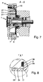
- FIGS. 7 and 8 show that in FIGS. 7 and 8 shown sixth embodiment.
- a rotating Paragraph 34 molded, while the inside of the end portion of the angled Edge part 17 of the side wall 9 facing the camshaft with a complementary one circumferential nose 35 is formed.
- This allows the camshaft to face Side wall 9 by simply clipping onto paragraph 34 of the Circumferential wall 7 are attached to the drive wheel 4.
- the in the boundary walls 11 through holes 37 are used again for the further Weight reduction of the device 1.
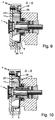
- the embodiment of the separate connection 18 shown in FIG Sidewall 9 facing the camshaft on the drive wheel 4 represents an alternative to the aforementioned embodiment.
- the Reduction in diameter of the outside of the peripheral wall 7 and thereby emerging circumferential paragraph 36 formed somewhat larger to the camshaft facing Sidewall 9 by crimping the angled end portion Edge section 17 around this shoulder 36 of the peripheral wall 7 on the drive wheel 4 to be able to attach.
- For sealing the side wall facing the camshaft 9 to the drive wheel 4 is again between them in the same way as in the first embodiment arranged O-ring 38 inserted, while the in the Boundary walls 11 incorporated through holes 37 also the Reduce the weight of the device 1.
- connection 18 of the camshaft-facing side wall 9 on the drive wheel 4 in the boundary walls 11 of the drive wheel 4 each parallel to Through bores 37 machined in the longitudinal center axis of the device 1 not just the weight reduction of the device 1.
- These through holes 37 are simultaneously used to attach the side wall facing the camshaft 9 used on the drive wheel 4 in such a way that it is characterized by punctiform Get through their outside into these through holes 37 without further fasteners jammed on the drive wheel.
- O-ring 38 arranged in the first embodiment also seals in this Embodiment, the camshaft-facing side wall 9 to the drive wheel 4th from.
Landscapes
- Engineering & Computer Science (AREA)
- Mechanical Engineering (AREA)
- General Engineering & Computer Science (AREA)
- Valve Device For Special Equipments (AREA)
- Valve-Gear Or Valve Arrangements (AREA)
Abstract
Description
- Figur 1
- eine Draufsicht auf eine erfindungsgemäß ausgebildete Vorrichtung bei demontierter nockenwellenabgewandter Seitenwand des Antriebsrades;
- Figur 2
- den Schnitt A-A nach Figur 1 mit einer ersten Ausführungsform der separaten Anbindung der nockenwellenzugewandten Seitenwand am Antriebsrad;
- Figur 3
- den Schnitt A-A nach Figur 1 mit einer zweiten Ausführungsform der separaten Anbindung der nockenwellenzugewandten Seitenwand am Antriebsrad;
- Figur 4
- den Schnitt A-A nach Figur 1 mit einer dritten Ausführungsform der separaten Anbindung der nockenwellenzugewandten Seitenwand am Antriebsrad;
- Figur 5
- den Schnitt A-A nach Figur 1 mit einer vierten Ausführungsform der separaten Anbindung der nockenwellenzugewandten Seitenwand am Antriebsrad;
- Figur 6
- den Schnitt A-A nach Figur 1 mit einer fünften Ausführungsform der separaten Anbindung der nockenwellenzugewandten Seitenwand am Antriebsrad;
- Figur 7
- den Schnitt A-A nach Figur 1 mit einer sechsten Ausführungsform der separaten Anbindung der nockenwellenzugewandten Seitenwand am Antriebsrad;
- Figur 8
- eine vergrößerte Darstellung der Einzelheit X nach Figur 7;
- Figur 9
- den Schnitt A-A nach Figur 1 mit einer siebten Ausführungsform der separaten Anbindung der nockenwellenzugewandten Seitenwand am Antriebsrad;
- Figur 10
- den Schnitt A-A nach Figur 1 mit einer achten Ausführungsform der separate Anbindung der nockenwellenzugewandten Seitenwand am Antriebsrad.
- 1
- Vorrichtung
- 2
- Zylinderkopf
- 3
- Nockenwelle
- 4
- Antriebsrad
- 5
- Flügelrad
- 6
- Verzahnung
- 7
- Umfangswand
- 8
- nockenwellenabgewandte Seitenwand
- 9
- nockenwellenzugewandte Seitenwand
- 10
- Hohlraum
- 11
- Begrenzungswände
- 12
- hydraulischer Arbeitsraum
- 13
- Radnabe
- 14
- Flügel
- 15
- Druckkammer
- 16
- Druckkammer
- 17
- Randpartie
- 18
- Anbindung
- 19
- Anschlussflansch
- 20
- Befestigungsflansche
- 21
- Schrauben
- 22
- O-Ring
- 23
- nockenwellenabgewandte Axialseiten
- 24
- Durchbruch
- 25
- Randpartie
- 26
- Simmerring
- 27
- nockenwellenzugewandte Axialseiten
- 28
- nockenwellenzugewandte Axialseite
- 29
- Ringnut
- 30
- Durchbrüche
- 31
- Federhülsen
- 32
- Durchbrüche
- 33
- Senkniete
- 34
- Absatz
- 35
- Nase
- 36
- Absatz
- 37
- Durchgangsbohrungen
- 38
- O-Ring
Claims (11)
- Vorrichtung zum Verändern der Steuerzeiten von Gaswechselventilen einer Brennkraftmaschine, insbesondere hydraulische Nockenwellen-Verstelleinrichtung in Rotationskolbenbauart, mit folgenden Merkmalen:dadurch gekennzeichnet, dassdie Vorrichtung (1) ist am antriebsseitigen Ende einer im Zylinderkopf (2) der Brennkraftmaschine gelagerten Nockenwelle (3) angeordnet und besteht im wesentlichen aus einem als Außenrotor ausgebildeten Antriebsrad (4) und aus einem als Innenrotor ausgebildeten Flügelrad (5),das Antriebsrad (4) steht über eine umlaufende Verzahnung (6) mit einer Kurbelwelle der Brennkraftmaschine in Antriebsverbindung und das Flügelrad (5) ist drehfest mit der Nockenwelle (3) der Brennkraftmaschine verbunden,das Antriebsrad (4) besteht desweiteren aus einer hohlzylindrischen Umfangswand (7), einer nockenwellenabgewandten Seitenwand (8) und einer nockenwellenzugewandten Seitenwand (9), die miteinander verbunden sind und zusammen einen Hohlraum (10) bilden,im Hohlraum (10) des Antriebsrades (4) wird durch mindestens zwei von der Innenseite der Umfangswand (7) ausgehende, radial zur Längsmittelachse der Vorrichtung (1) gerichtete Begrenzungswände (11) mindestens ein hydraulischer Arbeitsraum (12) gebildet,das Flügelrad (5) weist am Umfang seiner Radnabe (13) mindestens einen Flügel (14) auf, der sich radial in einen Arbeitsraum (12) des Antriebsrades (4) erstreckt und diesen in jeweils zwei hydraulische Druckkammern (15, 16) unterteilt,bei wahlweiser oder gleichzeitiger Druckbeaufschlagung der Druckkammern (15, 16) mit einem hydraulischen Druckmittel erfolgt eine Schwenkbewegung oder Fixierung des Flügelrades (5) gegenüber dem Antriebsrad (4) und damit der Nockenwelle (3) gegenüber der Kurbelwelle,die nockenwellenzugewandte Seitenwand (9) des Antriebsrades (4) als gewichts- und bauraumreduzierendes, dünnwandiges Rondenformteil ausgebildet ist,welches eine die Umfangswand (7) des Antriebsrades (4) wenigstens teilweise umschließende und zumindest nahezu rechtwinklig abgewinkelte Randpartie (17) aufweist,wobei die nockenwellenabgewandte Seitenwand (8), die Umfangswand (7) und die Verzahnung (6) des Antriebsrades (4) durch gemeinsame Befestigungen miteinander verbunden sind,und die nockenwellenzugewandte Seitenwand (9) durch eine separate, deren Axialsteifigkeit erhöhende Anbindung (18) am Antriebsrad (4) unlösbar befestigt ist.
- Vorrichtung nach Anspruch 1, dadurch gekennzeichnet, dass die Umfangswand (7) des Antriebsrades (4) an ihrer Außenseite einen bevorzugt umlaufenden, durchmesservergrößerten Anschlussflansch (19) aufweist, an dem rückseitig die den gleichen Durchmesser aufweisende nockenwellenabgewandte Seitenwand (8) und vorderseitig die als Zahnriemen-Ringrad mit mehreren radialen Befestigungsflanschen (20) ausgebildete Verzahnung (6) des Antriebsrades (4) durch gemeinsame Schrauben (21) befestigt ist.
- Vorrichtung nach Anspruch 1, dadurch gekennzeichnet, dass die nockenwellenzugewandte Seitenwand (9) des Antriebsrades (4) bevorzugt aus einem tiefgezogenen Stahlblech besteht, welches durch einen zentrischen Durchbruch (24) für die Nockenwelle (3), dessen Randpartie (25) zum Zylinderkopf (2) hin abgewinkelt und als Lauffläche für einen Simmerring (26) vorgesehenen ist, für eine riemengetriebene Vorrichtung (1) geeignet ausgebildet ist.
- Vorrichtung nach Anspruch 1, dadurch gekennzeichnet, dass die nockenwellenzugewandte Seitenwand (9) des Antriebsrades (4) bevorzugt durch punktförmiges Laserschweißen direkt an den nockenwellenzugewandten Axialseiten (27) der Begrenzungswände (11) des Antriebsrades (4) befestigt ist.
- Vorrichtung nach Anspruch 1, dadurch gekennzeichnet, dass die nockenwellenzugewandte Seitenwand (9) des Antriebsrades (4) bevorzugt durch Verkleben an den nockenwellenzugewandten Axialseiten (27, 28) der Begrenzungswände (11) und der Umfangswand (7) des Antriebsrades (4) befestigt ist.
- Vorrichtung nach Anspruch 1, dadurch gekennzeichnet, dass die nockenwellenzugewandte Axialseite (28) der Umfangswand (7) des Antriebsrades (4) bevorzugt eine umlaufende Ringnut (29) aufweist, in die ein ringförmiges Lotformteil eingelegt wird, welches durch Erhitzen die nockenwellenzugewandte Seitenwand (9) des Antriebsrades (4) durch Dichtlöten am Antriebsrad (4) befestigt.
- Vorrichtung nach Anspruch 1, dadurch gekennzeichnet, dass die Begrenzungswände (11) des Antriebsrades (4) jeweils parallel zur Längsmittelachse der Vorrichtung (1) verlaufende abgestufte Durchbrüche (30) aufweisen und die nockenwellenzugewandte Seitenwand (9) des Antriebsrades (4) bevorzugt durch Verschweißen an kopfseitig an den Stufen der Durchbrüche (30) anliegenden Federhülsen (31) am Antriebsrad (4) befestigt ist.
- Vorrichtung nach Anspruch 1, dadurch gekennzeichnet, dass die Begrenzungswände (11) des Antriebsrades (4) jeweils parallel zur Längsmittelachse der Vorrichtung (1) verlaufende abgestufte Durchbrüche (32) aufweisen und die nockenwellenzugewandte Seitenwand (9) des Antriebsrades (4) bevorzugt durch Vernieten mittels kopfseitig an den Stufen der Durchbrüche (32) anliegender Senkniete (33) am Antriebsrad (4) befestigt ist.
- Vorrichtung nach Anspruch 1, dadurch gekennzeichnet, dass die Außenseite der Umfangswand (7) des Antriebsrades (4) einen durch geringfügige Durchmesserverringerung gebildeten umlaufenden Absatz (34) aufweist und die nockenwellenzugewandte Seitenwand (9) des Antriebsrades (4) mittels einer an der Innenseite des Endbereiches ihrer abgewinkelten Randpartie (17) angeordneten umlaufenden Nase (35) durch Aufklipsen auf den Absatz (34) der Umfangswand (7) am Antriebsrad (4) befestigt ist.
- Vorrichtung nach Anspruch 1, dadurch gekennzeichnet, dass die Außenseite der Umfangswand (7) des Antriebsrades (4) einen durch geringfügige Durchmesserverringerung gebildeten umlaufenden Absatz (36) aufweist und die nockenwellenzugewandte Seitenwand (9) des Antriebsrades (4) durch Umbördeln des Endbereiches ihrer abgewinkelten Randpartie (17) um den Absatz (36) der Umfangswand (7) am Antriebsrad (4) befestigt ist.
- Vorrichtung nach Anspruch 1, dadurch gekennzeichnet, dass in die Begrenzungswände (11) des Antriebsrades (4) jeweils parallel zur Längsmittelachse der Vorrichtung (1) verlaufende Durchgangsbohrungen (37) eingearbeitet sind und die nockenwellenzugewandte Seitenwand (9) des Antriebsrades (4) bevorzugt durch punktförmiges Durchstellen ihrer Außenseite in diese Durchgangsbohrungen (37) hinein am Antriebsrad (4) befestigt ist.
Applications Claiming Priority (2)
| Application Number | Priority Date | Filing Date | Title |
|---|---|---|---|
| DE19951391A DE19951391A1 (de) | 1999-10-26 | 1999-10-26 | Vorrichtung zum Verändern der Steuerzeiten von Gaswechselventilen einer Brennkraftmaschine, insbesondere hydraulische Nockenwellen-Verstelleinrichtung in Rotationsrichtung |
| DE19951391 | 1999-10-26 |
Publications (2)
| Publication Number | Publication Date |
|---|---|
| EP1096112A1 true EP1096112A1 (de) | 2001-05-02 |
| EP1096112B1 EP1096112B1 (de) | 2004-09-15 |
Family
ID=7926822
Family Applications (1)
| Application Number | Title | Priority Date | Filing Date |
|---|---|---|---|
| EP00121419A Expired - Lifetime EP1096112B1 (de) | 1999-10-26 | 2000-09-29 | Vorrichtung zum Verändern der Steuerzeiten von Gaswechselventilen einer Brennkraftmaschine, insbesondere hydraulische Nockenwellen-Verstelleinrichtung in Rotationskolbenbauart |
Country Status (5)
| Country | Link |
|---|---|
| US (1) | US6418893B1 (de) |
| EP (1) | EP1096112B1 (de) |
| JP (1) | JP2001173415A (de) |
| AT (1) | ATE276432T1 (de) |
| DE (2) | DE19951391A1 (de) |
Cited By (1)
| Publication number | Priority date | Publication date | Assignee | Title |
|---|---|---|---|---|
| WO2010043462A1 (de) * | 2008-10-15 | 2010-04-22 | Schaeffler Kg | Vorrichtung zur variablen einstellung der steuerzeiten von gaswechselventilen einer brennkraftmaschine |
Families Citing this family (17)
| Publication number | Priority date | Publication date | Assignee | Title |
|---|---|---|---|---|
| DE10058707C2 (de) * | 2000-11-25 | 2003-10-16 | Porsche Ag | Vorrichtung zur relativen Drehwinkelverstellung einer Nockenwelle einer Brennkraftmaschine zu einem Antriebsrad |
| DE10141213B4 (de) * | 2001-08-23 | 2008-11-20 | Bayerische Motoren Werke Aktiengesellschaft | Anordnung einer Nockenwelle im Zylinderkopf einer Brennkraftmaschine |
| DE10359068A1 (de) * | 2003-12-16 | 2005-07-21 | Ina-Schaeffler Kg | Brennkraftmaschine mit einer hydraulischen Vorrichtung zur Drehwinkelverstellung einer Nockenwelle gegenüber einer Kurbelwelle |
| DE102004041430A1 (de) * | 2004-08-27 | 2006-03-09 | Daimlerchrysler Ag | Nockenwellenversteller |
| DE102004051424B4 (de) | 2004-10-22 | 2017-03-30 | Schaeffler Technologies AG & Co. KG | Vorrichtung zur Nockenwellenverstellung einer Brennkraftmaschine und Montagewerkzeug |
| DE102005013141B4 (de) * | 2005-03-22 | 2017-10-19 | Schaeffler Technologies AG & Co. KG | Vorrichtung zur Nockenwellenverstellung einer Brennkraftmaschine |
| US20060260578A1 (en) * | 2005-05-20 | 2006-11-23 | Schaeffler Kg | Apparatus for the variable setting of the control times of gas exchange valves of an internal combustion engine |
| DE102005024241B4 (de) | 2005-05-23 | 2017-08-17 | Schaeffler Technologies AG & Co. KG | Vorrichtung zur variablen Einstellung der Steuerzeiten von Gaswechselventilen einer Brennkraftmaschine |
| DE102007039282B4 (de) * | 2007-08-20 | 2017-06-01 | Hilite Germany Gmbh | Hydraulisch dichter Nockenwellenversteller |
| US8894530B1 (en) * | 2009-04-27 | 2014-11-25 | Thomas M. Read | Hypocycloidal crank apparatus |
| DE102010033978A1 (de) * | 2010-08-11 | 2012-02-16 | Andreas Stihl Ag & Co. Kg | Handgeführtes Arbeitsgerät |
| JP5569458B2 (ja) * | 2011-04-18 | 2014-08-13 | 株式会社デンソー | バルブタイミング調整装置 |
| DE102011050084B4 (de) * | 2011-05-04 | 2016-05-19 | Hilite Germany Gmbh | Schwenkmotorversteller |
| DE102012106426B4 (de) * | 2012-07-17 | 2017-06-22 | Hilite Germany Gmbh | Nockenwellenversteller |
| DE102012218405B4 (de) * | 2012-10-10 | 2014-08-21 | Schaeffler Technologies Gmbh & Co. Kg | Nockenwellenversteller mit rollierter Verbindung |
| DE102014200818A1 (de) * | 2014-01-17 | 2015-01-08 | Schaeffler Technologies Gmbh & Co. Kg | Zweigeteilter Stator mit kaltverschweißtem Deckel |
| DE102017119264B4 (de) * | 2017-08-23 | 2019-03-28 | Schaeffler Technologies AG & Co. KG | Nockenwellenversteller mit Dichtung zwischen Außendeckel und Stator |
Citations (6)
| Publication number | Priority date | Publication date | Assignee | Title |
|---|---|---|---|---|
| US4858572A (en) | 1987-09-30 | 1989-08-22 | Aisin Seiki Kabushiki Kaisha | Device for adjusting an angular phase difference between two elements |
| JPH08121122A (ja) * | 1994-10-20 | 1996-05-14 | Nippondenso Co Ltd | 内燃機関用バルブタイミング調整装置 |
| DE19829049A1 (de) | 1997-06-30 | 1999-01-07 | Aisin Seiki | Ventilsteuerungsvorrichtung |
| DE19756016A1 (de) * | 1997-12-17 | 1999-06-24 | Porsche Ag | Vorrichtung zur hydraulischen Drehwinkelverstellung einer Welle zu einem Antriebsrad |
| JPH11173119A (ja) * | 1997-12-12 | 1999-06-29 | Toyota Motor Corp | 内燃機関のバルブタイミング制御方法及びバルブタイミング制御装置 |
| US5941203A (en) * | 1997-06-24 | 1999-08-24 | Aisin Seiki Kabushiki Kaisha | Valve timing control device |
Family Cites Families (9)
| Publication number | Priority date | Publication date | Assignee | Title |
|---|---|---|---|---|
| JP3077621B2 (ja) * | 1996-04-09 | 2000-08-14 | トヨタ自動車株式会社 | 内燃機関の可変バルブタイミング機構 |
| JP3620684B2 (ja) * | 1997-01-31 | 2005-02-16 | 株式会社デンソー | 内燃機関用バルブタイミング調整装置 |
| JP3164007B2 (ja) * | 1997-02-14 | 2001-05-08 | トヨタ自動車株式会社 | 内燃機関のバルブタイミング調整装置 |
| JP3070547B2 (ja) * | 1997-10-24 | 2000-07-31 | 三菱電機株式会社 | 内燃機関のバルブタイミング制御装置 |
| JP3846605B2 (ja) * | 1997-10-30 | 2006-11-15 | アイシン精機株式会社 | 弁開閉時期制御装置 |
| JPH11141313A (ja) * | 1997-11-07 | 1999-05-25 | Toyota Motor Corp | 内燃機関のバルブタイミング変更装置 |
| JP3068806B2 (ja) * | 1997-12-15 | 2000-07-24 | 三菱電機株式会社 | 内燃機関のバルブタイミング制御装置 |
| US6269785B1 (en) * | 1998-01-29 | 2001-08-07 | Denso Corporation | Variable valve timing mechanism |
| JP3290422B2 (ja) * | 1999-04-26 | 2002-06-10 | 三菱電機株式会社 | 内燃機関のバルブタイミング制御装置 |
-
1999
- 1999-10-26 DE DE19951391A patent/DE19951391A1/de not_active Withdrawn
-
2000
- 2000-09-29 EP EP00121419A patent/EP1096112B1/de not_active Expired - Lifetime
- 2000-09-29 DE DE50007756T patent/DE50007756D1/de not_active Expired - Lifetime
- 2000-09-29 AT AT00121419T patent/ATE276432T1/de not_active IP Right Cessation
- 2000-10-25 US US09/696,576 patent/US6418893B1/en not_active Expired - Lifetime
- 2000-10-26 JP JP2000327455A patent/JP2001173415A/ja not_active Withdrawn
Patent Citations (6)
| Publication number | Priority date | Publication date | Assignee | Title |
|---|---|---|---|---|
| US4858572A (en) | 1987-09-30 | 1989-08-22 | Aisin Seiki Kabushiki Kaisha | Device for adjusting an angular phase difference between two elements |
| JPH08121122A (ja) * | 1994-10-20 | 1996-05-14 | Nippondenso Co Ltd | 内燃機関用バルブタイミング調整装置 |
| US5941203A (en) * | 1997-06-24 | 1999-08-24 | Aisin Seiki Kabushiki Kaisha | Valve timing control device |
| DE19829049A1 (de) | 1997-06-30 | 1999-01-07 | Aisin Seiki | Ventilsteuerungsvorrichtung |
| JPH11173119A (ja) * | 1997-12-12 | 1999-06-29 | Toyota Motor Corp | 内燃機関のバルブタイミング制御方法及びバルブタイミング制御装置 |
| DE19756016A1 (de) * | 1997-12-17 | 1999-06-24 | Porsche Ag | Vorrichtung zur hydraulischen Drehwinkelverstellung einer Welle zu einem Antriebsrad |
Non-Patent Citations (2)
| Title |
|---|
| PATENT ABSTRACTS OF JAPAN vol. 1996, no. 09 30 September 1996 (1996-09-30) * |
| PATENT ABSTRACTS OF JAPAN vol. 1999, no. 11 30 September 1999 (1999-09-30) * |
Cited By (1)
| Publication number | Priority date | Publication date | Assignee | Title |
|---|---|---|---|---|
| WO2010043462A1 (de) * | 2008-10-15 | 2010-04-22 | Schaeffler Kg | Vorrichtung zur variablen einstellung der steuerzeiten von gaswechselventilen einer brennkraftmaschine |
Also Published As
| Publication number | Publication date |
|---|---|
| US6418893B1 (en) | 2002-07-16 |
| DE19951391A1 (de) | 2001-07-05 |
| EP1096112B1 (de) | 2004-09-15 |
| JP2001173415A (ja) | 2001-06-26 |
| DE50007756D1 (de) | 2004-10-21 |
| ATE276432T1 (de) | 2004-10-15 |
Similar Documents
| Publication | Publication Date | Title |
|---|---|---|
| EP1096112B1 (de) | Vorrichtung zum Verändern der Steuerzeiten von Gaswechselventilen einer Brennkraftmaschine, insbesondere hydraulische Nockenwellen-Verstelleinrichtung in Rotationskolbenbauart | |
| DE102009054049B4 (de) | Nockenwellenverstellanordnung | |
| DE10134320A1 (de) | Vorrichtung zum Verändern der Steuerzeiten von Gaswechselventilen einer Brennkraftmaschine, insbesondere Rotationskolben-Verstelleinrichtung zur Drehwinkelverstellung einer Nockenwelle gegenüber einer Kurbelwelle | |
| DE102010050606A1 (de) | Rotor für einen Nockenwellenversteller sowie Nockenwellenversteller | |
| EP1426563A1 (de) | Turbolader mit keramischer oder metallischer Hitzeisolierung zwischen Turbinen- und Lagergehäuse | |
| EP1544419A1 (de) | Brennkraftmaschine mit einem hydraulischen Nockenwellenversteller mit einem als Blechteil ausgeführten Stator | |
| DE102012202520A1 (de) | Zentralventil für einen Nockenwellenversteller | |
| DE19745670A1 (de) | Vorrichtung zum Verändern der Steuerzeiten von Gaswechselventilen einer Brennkraftmaschine | |
| DE102012213176B4 (de) | Hydraulischer Nockenwellenversteller | |
| DE20221858U1 (de) | Brennkraftmaschine mit einer Vorrichtung zur hydraulischen Drehwinkelverstellung ihrer Nockenwelle gegenüber ihrer Kurbelwelle sowie mit einer Vakuumpumpe für einen Servoverbraucher, insbesondere für einen Bremskraftverstärker | |
| DE102009009252B4 (de) | Hydraulischer Nockenwellenversteller mit axialer Verschlussschraube | |
| DE102010060181A1 (de) | Zentralventil | |
| DE102009042228A1 (de) | Vorrichtung zur Veränderung der relativen Winkellage einer Nockenwelle gegenüber einer Kurbelwelle einer Brennkraftmaschine | |
| EP1828553A1 (de) | Nockenwellenversteller f]r eine brennkraftmaschine | |
| DE102011004403A1 (de) | Hydraulischer Ventiltrieb einer Brennkraftmaschine | |
| DE102013018775A1 (de) | Triebstock-Getriebeeinrichtung | |
| DE4321003C2 (de) | Vorrichtung zum Verändern der Steuerzeiten einer Brennkraftmaschine | |
| DE102010032133A1 (de) | Zentralventil | |
| DE19546934C2 (de) | Druckmittelabdichtung für eine Nockenwellenverstellvorrichtung | |
| DE102013203951A1 (de) | Steuerventil eines Nockenwellenverstellers | |
| DE102012200099A1 (de) | Nockenwellenversteller | |
| DE102012203383B3 (de) | Filteranordnung eines Steuerventils für einen Nockenwellenversteller | |
| WO2005108752A1 (de) | Hydraulischer nockenwellenversteller und verfahren zur montage desselben | |
| DE102004032141A1 (de) | Nockenwellenversteller | |
| DE19830100A1 (de) | Vorrichtung zum Verändern der Steuerzeiten von Gaswechselventilen einer Brennkraftmaschine, insbesondere Nockenwellen-Verstelleinrichtung mit Flügelrad |
Legal Events
| Date | Code | Title | Description |
|---|---|---|---|
| PUAI | Public reference made under article 153(3) epc to a published international application that has entered the european phase |
Free format text: ORIGINAL CODE: 0009012 |
|
| 17P | Request for examination filed |
Effective date: 20000929 |
|
| AK | Designated contracting states |
Kind code of ref document: A1 Designated state(s): AT BE CH CY DE DK ES FI FR GB GR IE IT LI LU MC NL PT SE |
|
| AX | Request for extension of the european patent |
Free format text: AL;LT;LV;MK;RO;SI |
|
| AKX | Designation fees paid |
Free format text: AT BE CH CY DE DK ES FI FR GB GR IE IT LI LU MC NL PT SE |
|
| RAP1 | Party data changed (applicant data changed or rights of an application transferred) |
Owner name: INA-SCHAEFFLER KG |
|
| GRAP | Despatch of communication of intention to grant a patent |
Free format text: ORIGINAL CODE: EPIDOSNIGR1 |
|
| GRAS | Grant fee paid |
Free format text: ORIGINAL CODE: EPIDOSNIGR3 |
|
| GRAA | (expected) grant |
Free format text: ORIGINAL CODE: 0009210 |
|
| AK | Designated contracting states |
Kind code of ref document: B1 Designated state(s): AT BE CH CY DE DK ES FI FR GB GR IE IT LI LU MC NL PT SE |
|
| PG25 | Lapsed in a contracting state [announced via postgrant information from national office to epo] |
Ref country code: CY Free format text: LAPSE BECAUSE OF FAILURE TO SUBMIT A TRANSLATION OF THE DESCRIPTION OR TO PAY THE FEE WITHIN THE PRESCRIBED TIME-LIMIT Effective date: 20040915 Ref country code: NL Free format text: LAPSE BECAUSE OF FAILURE TO SUBMIT A TRANSLATION OF THE DESCRIPTION OR TO PAY THE FEE WITHIN THE PRESCRIBED TIME-LIMIT Effective date: 20040915 Ref country code: IE Free format text: LAPSE BECAUSE OF FAILURE TO SUBMIT A TRANSLATION OF THE DESCRIPTION OR TO PAY THE FEE WITHIN THE PRESCRIBED TIME-LIMIT Effective date: 20040915 Ref country code: FI Free format text: LAPSE BECAUSE OF FAILURE TO SUBMIT A TRANSLATION OF THE DESCRIPTION OR TO PAY THE FEE WITHIN THE PRESCRIBED TIME-LIMIT Effective date: 20040915 |
|
| REG | Reference to a national code |
Ref country code: GB Ref legal event code: FG4D Free format text: NOT ENGLISH Ref country code: CH Ref legal event code: EP |
|
| PG25 | Lapsed in a contracting state [announced via postgrant information from national office to epo] |
Ref country code: LU Free format text: LAPSE BECAUSE OF NON-PAYMENT OF DUE FEES Effective date: 20040929 Ref country code: AT Free format text: LAPSE BECAUSE OF NON-PAYMENT OF DUE FEES Effective date: 20040929 |
|
| PG25 | Lapsed in a contracting state [announced via postgrant information from national office to epo] |
Ref country code: MC Free format text: LAPSE BECAUSE OF NON-PAYMENT OF DUE FEES Effective date: 20040930 Ref country code: CH Free format text: LAPSE BECAUSE OF NON-PAYMENT OF DUE FEES Effective date: 20040930 Ref country code: BE Free format text: LAPSE BECAUSE OF NON-PAYMENT OF DUE FEES Effective date: 20040930 Ref country code: LI Free format text: LAPSE BECAUSE OF NON-PAYMENT OF DUE FEES Effective date: 20040930 |
|
| REG | Reference to a national code |
Ref country code: IE Ref legal event code: FG4D Free format text: GERMAN |
|
| REF | Corresponds to: |
Ref document number: 50007756 Country of ref document: DE Date of ref document: 20041021 Kind code of ref document: P |
|
| PG25 | Lapsed in a contracting state [announced via postgrant information from national office to epo] |
Ref country code: SE Free format text: LAPSE BECAUSE OF FAILURE TO SUBMIT A TRANSLATION OF THE DESCRIPTION OR TO PAY THE FEE WITHIN THE PRESCRIBED TIME-LIMIT Effective date: 20041215 Ref country code: GR Free format text: LAPSE BECAUSE OF FAILURE TO SUBMIT A TRANSLATION OF THE DESCRIPTION OR TO PAY THE FEE WITHIN THE PRESCRIBED TIME-LIMIT Effective date: 20041215 Ref country code: DK Free format text: LAPSE BECAUSE OF FAILURE TO SUBMIT A TRANSLATION OF THE DESCRIPTION OR TO PAY THE FEE WITHIN THE PRESCRIBED TIME-LIMIT Effective date: 20041215 |
|
| PG25 | Lapsed in a contracting state [announced via postgrant information from national office to epo] |
Ref country code: ES Free format text: LAPSE BECAUSE OF FAILURE TO SUBMIT A TRANSLATION OF THE DESCRIPTION OR TO PAY THE FEE WITHIN THE PRESCRIBED TIME-LIMIT Effective date: 20041226 |
|
| GBT | Gb: translation of ep patent filed (gb section 77(6)(a)/1977) |
Effective date: 20050125 |
|
| BERE | Be: lapsed |
Owner name: INA-SCHAEFFLER K.G. Effective date: 20040930 |
|
| NLV1 | Nl: lapsed or annulled due to failure to fulfill the requirements of art. 29p and 29m of the patents act | ||
| REG | Reference to a national code |
Ref country code: IE Ref legal event code: FD4D |
|
| REG | Reference to a national code |
Ref country code: CH Ref legal event code: PL |
|
| PLBE | No opposition filed within time limit |
Free format text: ORIGINAL CODE: 0009261 |
|
| STAA | Information on the status of an ep patent application or granted ep patent |
Free format text: STATUS: NO OPPOSITION FILED WITHIN TIME LIMIT |
|
| ET | Fr: translation filed | ||
| PGFP | Annual fee paid to national office [announced via postgrant information from national office to epo] |
Ref country code: FR Payment date: 20050823 Year of fee payment: 6 |
|
| 26N | No opposition filed |
Effective date: 20050616 |
|
| PGFP | Annual fee paid to national office [announced via postgrant information from national office to epo] |
Ref country code: GB Payment date: 20050928 Year of fee payment: 6 |
|
| PGFP | Annual fee paid to national office [announced via postgrant information from national office to epo] |
Ref country code: IT Payment date: 20060930 Year of fee payment: 7 |
|
| GBPC | Gb: european patent ceased through non-payment of renewal fee |
Effective date: 20060929 |
|
| REG | Reference to a national code |
Ref country code: FR Ref legal event code: ST Effective date: 20070531 |
|
| PG25 | Lapsed in a contracting state [announced via postgrant information from national office to epo] |
Ref country code: GB Free format text: LAPSE BECAUSE OF NON-PAYMENT OF DUE FEES Effective date: 20060929 |
|
| BERE | Be: lapsed |
Owner name: *INA-SCHAEFFLER K.G. Effective date: 20040930 |
|
| PG25 | Lapsed in a contracting state [announced via postgrant information from national office to epo] |
Ref country code: PT Free format text: LAPSE BECAUSE OF NON-PAYMENT OF DUE FEES Effective date: 20050215 |
|
| PG25 | Lapsed in a contracting state [announced via postgrant information from national office to epo] |
Ref country code: FR Free format text: LAPSE BECAUSE OF NON-PAYMENT OF DUE FEES Effective date: 20061002 |
|
| PG25 | Lapsed in a contracting state [announced via postgrant information from national office to epo] |
Ref country code: IT Free format text: LAPSE BECAUSE OF NON-PAYMENT OF DUE FEES Effective date: 20070929 |
|
| REG | Reference to a national code |
Ref country code: DE Ref legal event code: R081 Ref document number: 50007756 Country of ref document: DE Owner name: SCHAEFFLER TECHNOLOGIES AG & CO. KG, DE Free format text: FORMER OWNER: SCHAEFFLER TECHNOLOGIES GMBH & CO. KG, 91074 HERZOGENAURACH, DE Effective date: 20120828 Ref country code: DE Ref legal event code: R081 Ref document number: 50007756 Country of ref document: DE Owner name: SCHAEFFLER TECHNOLOGIES GMBH & CO. KG, DE Free format text: FORMER OWNER: SCHAEFFLER TECHNOLOGIES GMBH & CO. KG, 91074 HERZOGENAURACH, DE Effective date: 20120828 |
|
| REG | Reference to a national code |
Ref country code: DE Ref legal event code: R081 Ref document number: 50007756 Country of ref document: DE Owner name: SCHAEFFLER TECHNOLOGIES GMBH & CO. KG, DE Free format text: FORMER OWNER: SCHAEFFLER TECHNOLOGIES AG & CO. KG, 91074 HERZOGENAURACH, DE Effective date: 20140213 Ref country code: DE Ref legal event code: R081 Ref document number: 50007756 Country of ref document: DE Owner name: SCHAEFFLER TECHNOLOGIES AG & CO. KG, DE Free format text: FORMER OWNER: SCHAEFFLER TECHNOLOGIES AG & CO. KG, 91074 HERZOGENAURACH, DE Effective date: 20140213 |
|
| REG | Reference to a national code |
Ref country code: DE Ref legal event code: R081 Ref document number: 50007756 Country of ref document: DE Owner name: SCHAEFFLER TECHNOLOGIES AG & CO. KG, DE Free format text: FORMER OWNER: SCHAEFFLER TECHNOLOGIES GMBH & CO. KG, 91074 HERZOGENAURACH, DE Effective date: 20150210 |
|
| PGFP | Annual fee paid to national office [announced via postgrant information from national office to epo] |
Ref country code: DE Payment date: 20191129 Year of fee payment: 20 |
|
| REG | Reference to a national code |
Ref country code: DE Ref legal event code: R071 Ref document number: 50007756 Country of ref document: DE |
|
| P01 | Opt-out of the competence of the unified patent court (upc) registered |
Effective date: 20230522 |