EP1094188A2 - Türschwelle - Google Patents
Türschwelle Download PDFInfo
- Publication number
- EP1094188A2 EP1094188A2 EP00122006A EP00122006A EP1094188A2 EP 1094188 A2 EP1094188 A2 EP 1094188A2 EP 00122006 A EP00122006 A EP 00122006A EP 00122006 A EP00122006 A EP 00122006A EP 1094188 A2 EP1094188 A2 EP 1094188A2
- Authority
- EP
- European Patent Office
- Prior art keywords
- door
- profile
- door sill
- sill according
- slip
- Prior art date
- Legal status (The legal status is an assumption and is not a legal conclusion. Google has not performed a legal analysis and makes no representation as to the accuracy of the status listed.)
- Granted
Links
Images



Classifications
-
- E—FIXED CONSTRUCTIONS
- E06—DOORS, WINDOWS, SHUTTERS, OR ROLLER BLINDS IN GENERAL; LADDERS
- E06B—FIXED OR MOVABLE CLOSURES FOR OPENINGS IN BUILDINGS, VEHICLES, FENCES OR LIKE ENCLOSURES IN GENERAL, e.g. DOORS, WINDOWS, BLINDS, GATES
- E06B1/00—Border constructions of openings in walls, floors, or ceilings; Frames to be rigidly mounted in such openings
- E06B1/70—Sills; Thresholds
-
- E—FIXED CONSTRUCTIONS
- E06—DOORS, WINDOWS, SHUTTERS, OR ROLLER BLINDS IN GENERAL; LADDERS
- E06B—FIXED OR MOVABLE CLOSURES FOR OPENINGS IN BUILDINGS, VEHICLES, FENCES OR LIKE ENCLOSURES IN GENERAL, e.g. DOORS, WINDOWS, BLINDS, GATES
- E06B1/00—Border constructions of openings in walls, floors, or ceilings; Frames to be rigidly mounted in such openings
- E06B1/70—Sills; Thresholds
- E06B2001/707—Thresholds with special provision for insulation
Definitions
- the invention relates to a threshold, with a Metal profile on which an insulating profile made of plastic is locked, the inside of the door is vertical Has door hinge and is provided with an appearance.
- a door sill with the features mentioned above is known from EP-A-0 851 057.
- the thermal insulation profile extends practically half the width of the threshold. It consists of a smooth plastic and also the appearance the threshold is accordingly smooth. Accordingly the risk of slipping is very high.
- the invention has for its object a threshold to improve with the features mentioned at the beginning, that the risk of slipping in the area of the appearance is reduced becomes.
- the above object is achieved in that the Appearance on a tread of the insulation profile or one Cover the insulating profile with a non-slip pad is.
- the tread surface has a non-slip pad.
- the slip resistance is so large that it has a non-slip load many use cases allowed. For example when entering or when driving on it is not possible, for example the foot due to an inclined position on the tread starts to slide. He finds both a high coefficient of friction on the outer surface of the non-slip pad before, as this also suffices on the smooth appearance is fixed.
- the non-slip pad offers all loads with a horizontal component a very large coefficient of friction, so that, for example, the foot that occurs cannot slide horizontally.
- the high coefficient of friction also contributes to a better grip for driving is achieved. For example, a wheelchair user reaches a better one when crossing the threshold, namely non-slip hold on the threshold or on the threshold Appearance.
- the door threshold is advantageously designed so that the non-slip pad is made of soft material.
- the soft material provides resilience so that it is stressful Can impress elements.
- the Slip resistance except due to the high coefficient of friction non-slip pad also due to a certain form fit of the burdening object with the non-slip pad increased.
- the non-slip pad has especially with her Training from soft material has the advantage that it is Insulation profile against external influences due to mechanical stress, Protects wear, pollution, etc. because of a soft Element is usually not subject to as much wear, like a hard element.
- the non-slip pad it is possible to design the non-slip pad so that they are sufficient on the plastic insulation profile lies non-slip because it is sufficiently large Has contact surface. Usually, however, it is preferable when the non-slip pad is glued to the tread and / or is locked to it. Gluing and snapping the non-slip pad on the tread surface secures one immovable position of the non-slip pad on the tread even if the circulation to a considerable extent is cross-loaded, for example at its ends and for example due to a door seal attached to the door leaf.
- the firm connection provides the non-slip Edition with the insulation profile or with the Threshold the advantage that an improvement in manageability is achieved.
- the door threshold can also be factory-made are prefabricated so that the non-slip pad at installation on site is not forgotten.
- a door threshold is particularly advantageous, where the non-slip pad with the tread of the insulation profile is co-extruded.
- the non-slip pad it becomes inseparable from the appearance of the perineum profile connected.
- the edge strength in particular is considerable, so that the edges of the non-slip pad in the tread are practically impossible to solve. That is in view to the high edge stress of door sills from special meaning.
- the door sill so that the non-slip pad on the tread side to the outside sloping, the support if necessary inside the door is thicker than outside. This ensures that about the tread or their Non-slip surface water due to the inclination can run outwards.
- the inclination can be consistently with one equal thickness can be achieved by the insulation profile or its tread surface inclined accordingly is profiled.
- the tread it is also possible to use the tread to be horizontal and a greater thickness on the inside of the door to provide the non-slip pad. The latter is special with regard to the high edge load inside the door advantageous, for example by a on the lower edge of the Door wing provided sealing strip rubbing over the edge.
- the threshold it is advisable to design the threshold so that the non-slip pad made of elastic plastic and / or synthetic rubber and / or natural rubber and / or made of natural non-slip material. More elastic Plastic and / or synthetic rubber are wear and tear Resistant to rotting and therefore for use with a Door threshold particularly suitable. Because there are doorsteps usually in a building area that is mechanical is highly stressed, namely by entering, and in which is particularly at risk of contamination.
- the threshold can be designed so that the non-slip Overlay a smooth and / or closed-pore outer surface having. Deposited dirt then finds a smooth one Surface in front of which it cannot adhere well. With closed-pore Training the dirt is also unable to penetrate the non-slip pad. This therefore remains clean and handsome.
- the threshold it is particularly advantageous to design the threshold so that that a sliding seal of a closed door leaf is supported on the non-slip pad.
- the Slip seal becomes a due to the higher static friction Can withstand greater wind pressure than when on a smooth Metal or plastic surface would be supported.
- the door sill it is advantageous to design the door sill to coordinate the arrangement of the non-slip pad.
- the threshold is designed so that the non-slip Edition is arranged on a threshold leg, the is locked with the metal profile.
- the non-slip pad or the threshold leg carrying it in the immediate supporting neighborhood to the metal profile arranged. This is beneficial for stable behavior the door sill consisting of several components.
- Another advantageous embodiment stands out characterized in that the appearance of an outwardly projecting Skirting board adjoins that on the tread side of the non-slip pad is covered.
- the non-slip Overlay as far out as possible, especially in the case where the insulation profile in Regarding the metal profile extends far out.
- the threshold leg one if necessary with a Screw channel provided stiffening strip that on rests on the metal profile and is connected to it if necessary is.
- the threshold leg is stiffened and supported there at the same time by the metal profile, so that has a very compact construction, in particular of The advantage is when the locking engagement between the threshold leg and is adjacent to the metal profile.
- the door sill advantageously designed so that the stop leg is at least single-walled and the additional latching as Support latch in relation to the metal profile at medium height or arranged on a floor support level of the metal profile is.
- the additional support lock stabilizes the single-walled stop leg in the event that the vertical door stop has to absorb greater impact forces.
- the catches are not applied in the release direction, not particularly support latches.
- the threshold can be designed so that the Skirting board and / or the locking bar from a compliant Material. This will hold the locking bar or improved the safety of rest, because occurring Loads absorbed by the compliant material and do not act on the locking connection in the sense of separation.
- the non-slip pad works in the same sense.
- a further embodiment of the door sill is in this regard possible that the fillet and / or the locking bar part the insulation profile, the cover or the non-slip Support of the insulation profile or its cover is or are. If the molding and / or the locking bar with the insulation profile, with its cover or in one piece with the support trained, there are considerable advantages in the manufacture of the respective combinations of components.
- the components can be made in one piece from the same material or are made from different materials, for example by coextrusion. The construction can be matched to the load.
- the door sill so that the lid is made of metal and inside the door is insulated with the non-slip pad.
- the non-slip pad prevents signs of condensation can take place on the cover.
- the non-slip pad For a door sill with plastic Insulation profile, it is preferable that the non-slip pad the plastic protrusion protruding outwards around the existing insulation profile up to the locking strip on the outside.
- the non-slip pad prevents damage to the projecting Skirting board especially at low outside temperatures.
- the different door thresholds shown in the figures 10 each consist essentially of a metal profile 11 and an insulating profile made of plastic 12. They are assembled so that one results in a flat door sill that underneath a door leaf 18 be arranged at least with part of their insulation profile 12 can.
- the door sills 10 adjoin an inside of the door 26 and on a door outside 27. Both are by the Door leaf 18 separated from each other.
- the door leaf 18 has one Rollover 28, with which he on a vertical door hinge 13th can apply, for example by means of a not shown, seal buttoned into rollover groove 28 '.
- the door leaf on the threshold 10 also be sealed with a sliding seal 17, the an end face 18 'of the door leaf 18 is attached.
- Each insulation profile 12 has a threshold leg 16 provided which extends substantially horizontally and forms an appearance 14. Vertical to the threshold leg 16 there is a stop leg 19 with a door stop 13 is provided, on which the door leaf 17 in its Supports the closed position.
- the appearance 14 ends on the outside with a fillet 20, the one with a locking bar 21 Throat 31 forms that above a tread surface 11 'of the metal profile 11 is arranged.
- Thresholds are often loaded with momentum, especially from the outside of the door. It is therefore advantageous yield in the relevant load areas To provide material.
- 1a shows a design of the insulation profile 12, in which the associated mold 20 and the Snap bar 21 each consist of such a compliant material for example PUR foam.
- Such or another Plastic can, for example, with the insulation profile 12 Coextruded are manufactured.
- the compliance ensures for impacts that occur, for example when rolling up with a wheelchair or when bumping into one Shoe not fully on the locking connection between the locking bar 21 and a latching hook 36 of the metal profile 11 impact.
- the tread 14 is provided with a tread surface 14 ', which is covered with a non-slip pad 15.
- the Coverage is complete in all display cases, So from the vertical door stop 13 to the moldings 20.
- Die Non-slip pad 15 is designed so that it on her the edge adjacent to the door stop 13 is made thicker, than on its edge adjacent to the fillet 20. Your As a result, the outer surface 15 'is inclined from the inside to the outside. Moisture or rainwater can follow run outside. This is particularly the case if the Outer surface 15 'is smooth and / or closed-pore. Also With such a training, pollution occurs only to a small extent Scope.
- the seal is also supported the grinding seal 17; because of the inclination of the outer surface 15 'pressing wind can brush the bristles of the grinding seal 17 press hard on the rollover 28 and thus penetrate into the sealed area. That applies especially when the non-slip pad 15 is high Has coefficient of friction, as is the case when it consists of soft material, for example elastic Plastic and / or synthetic rubber.
- Fig.1 shows another Design of a connection of the pad 15 with the Tread surface 14 ', in which the threshold leg 16 with the Edition 15 is locked, for which the threshold leg 16 holes or has slots as recesses in the point-like or strip-like projections 15 ′′ of the support 15 engage.
- a latching remains the closed cohesion of the hollow chamber 15 provided insulation profile 12 in the sense of high stability.
- Fig.1 shows an insulation profile 12 with a hollow chamber 25, in which the stop leg 19 is a stiffening wall 32 is arranged in parallel, which in turn is on the bottom side with a connecting wall 33 with the stop leg 19 is integrally connected.
- One with this bottom wall 33 aligned locking leg 34 is with a locking hook 35 Metal profile 11 locked.
- Vertically above that previously described Latch is a latch between the Locking bar 21 and a locking hook 36 of the metal profile 11.
- the latching hook 36 engages in a latching groove 37 of the insulation profile 12, which between the wall 32 and the Snap bar 21 is formed.
- the insulation profile 12 and the metal profile 11 become temperature loads subject to mutual interconnection may be heavily used via locking means. It is therefore provided that the metal profile 11 with a additional fuse strip 42 is provided, which also is locked with the locking leg 34.
- the fuse strip 42 has either the one with solid lines Training or a different training, for example according to the arrangement 42 'around this locking engagement with a view to a more forceful assembly to train. The fuse strip 42 can then be locked deform to the required extent with the insulation profile 12, if the connecting wall 33 between the locking hooks 35 and the fuse strip 42 in the illustrated or in a similar position.
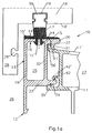
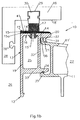
- 1b, 1c door thresholds 10 are shown at which the appearance 14 or its tread 14 'is covered with a cover 41.
- the lid 41 can with strip-like projections 15 '' in arches or slots of the Intervene step 14, as was described for Fig.1.
- the material of the cover 41 is, for example, a hard plastic, the carrier for a non-slip pad 15 is which performs the same tasks as the non-slip Edition 15 to Fig.1 has been described.
- the lid 41 can also have a shape different from that shown, for example as in the German utility model 296 02 408, in which the cover covers a channel leading to Inclusion of screw heads for fastening screws necessary with which the threshold is screwed to the floor becomes.
- the cover 41 can also be made of metal.
- The is in the sense of a long durability and a big one Stability desirable. In this case, however, care must be taken that there is no moisture formation on the metal occurs through condensation. For this reason, in Fig.1b shown that the cover at a distance from the door stop 13th ends and the inside edge of the lid with additional Material 15a of the non-slip pad 15 covered with heat insulation is.
- the cover 41 is made of a non-slip Plastic built up with the fillet 20 and with the Snap bar 21 is in one piece.
- the sturdy foam is for example a PUR foam.
- the one-piece training of the Fillet 20 and the locking bar 21 with the lid 41 has the Advantage that larger and short-term loads the threshold in the area of the metal profile 10 are collected can, if they hit the groin and the Plastic is elastic to a certain extent.
- the rest connection the locking bar 21 with the locking hook 36 then claimed to a lesser extent, which is for the permanent Cohesion of the profiles 11, 12 is advantageous.
- the fillet 20 and the locking bar 21 are in one piece with the lid 41, but must be designed that a latching of the cover 41 with the insulation profile 12th is made possible, as is the above-described latching under Use of the locking bar 21.
- Fig.1d shows an embodiment of a threshold the appearance 14 with a special non-slip pad 15 is covered.
- the appearance 14 is described in FIG Way provided with a fillet 20 to which a locking bar 21 connects to couple the profile 11 to the profile 12 to be able to.
- the plastic profile 12 or however, its outside molding 20 is special exposed to mechanical stress. In particular kick Shock loads on. Such shock loads can primarily cause damage at low outside temperatures.
- the non-slip pad 15 engages with a Pad 15 '' 'the groin 20.
- the grasping of the Groove 20 extends into the area of the locking bar 21 so that the fillet 20 on the one hand from the support 15th is protected against cold, but above all against shocks, which are buffered by the pad 15 '' '.
- An additional locking is between the threshold leg 16 and the metal profile 11 provided, namely in Area of a vertical support wall 11 ′′ of the metal profile, which is parallel to the stop leg 19.
- this additional catch as a support catch 24 form, in which a locking bar 39 of two Snap bars 40 is gripped vertically in a form-fitting manner.
- the bars 39.40 from the horizontal of the support leg 11 '' to the threshold leg 16 inclined upwards. That makes it easier the assembly of the insulation profile 12 with the metal profile 11 when establishing the locking between the locking bar 21 and the locking groove 38.
- the single-walled stop leg 19 is stiffened.
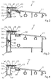
- a support latch 24 especially for higher thresholds 10 is required and in the case of a lower threshold results in a very compact and overall stable design. If such stability is not desired, the 4 are formed where the stop leg 19 with a hook wall 19 "the support wall 11" of Metal profile 11 engages behind.
Landscapes
- Engineering & Computer Science (AREA)
- Civil Engineering (AREA)
- Structural Engineering (AREA)
- Specific Sealing Or Ventilating Devices For Doors And Windows (AREA)
- Door And Window Frames Mounted To Openings (AREA)
Abstract
Description
- Fig.1
- einen schematisierten Querschnitt durch eine Türschwelle im Bereich ihres türinnenseitigen Dämmprofils mit angedeuteter Stellung eines Türflügels,
- Fig.1a bis Fig.1d
- modifizierte Ausführungsformen der Türschwelle in Fig.1 entsprechenden Darstellungen,
- Fig.2
- einen totalen Querschnitt einer gegenüber der Fig.1 abgeänderten Türschwelle,
- Fig.3 und 4
- der Fig.2 ähnliche Türschwellen, die in die Erfindung betreffenden Details abgeändert sind.
Claims (21)
- Türschwelle (10), mit einem Metallprofil (11), an dem aus Kunststoff bestehendes Dämmprofil (12) verrastet ist, das türinnenseitig einen vertikalen Türanschlag (13) aufweist und mit einem Auftritt (14) versehen ist, dadurch gekennzeichnet, daß der Auftritt (14) auf einer Auftrittsfläche (14') des Dämmprofils (12) oder eines Deckels (41) des Dämmprofils (12) mit einer rutschfesten Auflage (15) versehen ist.
- Türschwelle nach Anspruch 1, dadurch gekennzeichnet, daß die gesamte Auftrittsfläche (14') von der rutschfesten Auflage (15) abgedeckt ist.
- Türschwelle nach Anspruch 1 oder 2, dadurch gekennzeichnet, daß die rutschfeste Auflage (15) aus weichem Material besteht.
- Türschwelle nach einem oder mehreren der Ansprüche 1 bis 3, dadurch gekennzeichnet, daß die rutschfeste Auflage (15) auf die Auftrittsfläche (14') geklebt und/oder daran verrastet ist.
- Türschwelle nach einem oder mehreren der Ansprüche 1 bis 4, dadurch gekennzeichnet, daß die rutschfeste Auflage (15) mit der Auftrittsfläche (14') des Dammprofils (12) koextrudiert ist.
- Türschwelle nach einem oder mehreren der Ansprüche 1 bis 5, dadurch gekennzeichnet, daß die rutschfeste Auflage (15) auftrittseitig nach außen abfallend geneigt ist, wobei die Auflage (15) bedarfsweise türinnenseitig dicker ist als außen.
- Türschwelle nach einem oder mehreren der Ansprüche 1 bis 6, dadurch gekennzeichnet, daß die rutschfeste Auflage aus elastischem Kunststoff und/oder synthetischem Kautschuk und/oder aus Naturkautschuk und/oder aus natürlichem rutschfestem Werkstoff besteht.
- Türschwelle nach einem oder mehreren der Ansprüche 1 bis 7, dadurch gekennzeichnet, daß die rutschfeste Auflage (15) eine glatte und/oder geschlossenporige Außenfläche (15') aufweist.
- Türschwelle nach einem oder mehreren der Ansprüche 1 bis 8, dadurch gekennzeichnet, daß eine Schleifdichtung (17) eines geschlossenen Türflügels (18) auf der rutschfesten Auflage (15) abgestützt ist.
- Türschwelle nach einem oder mehreren der Ansprüche 1 bis 9, dadurch gekennzeichnet, daß die rutschfeste Auflage (15) auf einem Schwellenschenkel (16) angeordnet ist, der mit dem Metallprofil (11) verrastet ist.
- Türschwelle nach einem oder mehreren der Ansprüche 1 bis 10, dadurch gekennzeichnet, daß das Dämmprofil (12) sowohl mittels des Schwellenschenkels (16) als auch mittels eines den vertikalen Türanschlag (13) aufweisenden Anschlagschenkels (19) am Metallprofil (11) zusätzlich verrastet ist.
- Türschwelle nach einem oder mehreren der Ansprüche 1 bis 11, dadurch gekennzeichnet, daß der Auftritt (14) an eine nach außen vorspringende Kehlleiste (20) angrenzt, die von der rutschfesten Auflage (15) auftrittseitig abgedeckt ist.
- Türschwelle nach einem oder mehreren der Ansprüche 1 bis 12, dadurch gekennzeichnet, daß an die Kehlleiste (20) eine an dem Metallprofil (11) angreifende Rastleiste (21) anschließt, deren Rasteingriff mit dem Metallprofil (7) zumindest zum Teil von der rutschfesten Auflage (15) überdeckt ist.
- Türschwelle nach einem oder mehreren der Ansprüche 1 bis 13, dadurch gekennzeichnet, daß der Schwellenschenkel (16) eine bedarfsweise mit einem Schraubkanal (22) versehene Versteifungsleiste (23) aufweist, die auf dem Metallprofil (11) aufliegt und bedarfweise damit verbunden ist.
- Türschwelle nach einem oder mehreren der Ansprüche 1 bis 14, dadurch gekennzeichnet, daß der Anschlagschenkel (19) mindestens einwandig ist und die zusätzliche Verrastung als Abstützverrastung (24) in Bezug zum Metallprofil (11) auf mittlerer Höhe oder auf einer Bodenauflageebene des Metallprofils (11) angeordnet ist.
- Türschwelle nach einem oder mehreren der Ansprüche 1 bis 15, dadurch gekennzeichnet, daß das Dämmprofil (12) türinnenseitig eine Hohlkammer (25) aufweist, und daß die Verrastung des Schwellenschenkels (16) und die Abstützverrastung (24) vertikal übereinander unterhalb der rutschfesten Auflage (15) angeordnet ist.
- Türschwelle nach einem oder mehreren der Ansprüche 1 bis 16, dadurch gekennzeichnet, daß die Kehlleiste (20) und/oder die Rastleiste (21) aus einem nachgiebigen Werkstoff bestehen.
- Türschwelle nach einem oder mehreren der Ansprüche 1 bis 17, dadurch gekennzeichnet, daß die Kehlleiste (20) und/oder die Rastleiste (21) Bestandteil des Dämmprofils (12), des Deckels (41) oder der rutschfesten Auflage (15) des Dämmprofils (12) oder dessen Deckels (36) ist beziehungsweise sind.
- Türschwelle nach einem oder mehreren der Ansprüche 1 bis 18, dadurch gekennzeichnet, daß der Deckel (41) aus Metall besteht und türinnenseitig mit der rutschfesten Auflage (15) wärmegedämmt ist.
- Türschwelle nach einem oder mehreren der Ansprüche 1 bis 19, dadurch gekennzeichnet, daß das Metallprofil (11) mit einem kältebedingten Auseinanderrutschen des aus Kunststoff bestehenden Dämmprofils (12) und des Metallprofils (11) verhindernden Sicherungsleiste (42) versehen ist.
- Türschwelle nach einem oder mehreren der Ansprüche 1 bis 20, dadurch gekennzeichnet, daß die rutschfeste Auflage (15) die nach außen vorspringende Kehlleiste (20) des aus Kunststoff bestehenden Dämmprofils (12) bis zur Rastleiste (21) außen umgreift.
Applications Claiming Priority (2)
| Application Number | Priority Date | Filing Date | Title |
|---|---|---|---|
| DE19950473A DE19950473A1 (de) | 1999-06-12 | 1999-10-20 | Türschwelle |
| DE19950473 | 1999-10-20 |
Publications (3)
| Publication Number | Publication Date |
|---|---|
| EP1094188A2 true EP1094188A2 (de) | 2001-04-25 |
| EP1094188A3 EP1094188A3 (de) | 2002-10-02 |
| EP1094188B1 EP1094188B1 (de) | 2005-04-06 |
Family
ID=7926247
Family Applications (1)
| Application Number | Title | Priority Date | Filing Date |
|---|---|---|---|
| EP00122006A Expired - Lifetime EP1094188B1 (de) | 1999-10-20 | 2000-10-10 | Türschwelle |
Country Status (2)
| Country | Link |
|---|---|
| EP (1) | EP1094188B1 (de) |
| AT (1) | ATE292731T1 (de) |
Cited By (1)
| Publication number | Priority date | Publication date | Assignee | Title |
|---|---|---|---|---|
| CN115257086A (zh) * | 2022-07-25 | 2022-11-01 | 尹梅 | 一种内置气凝胶复合板的玻璃及其制备方法 |
Citations (1)
| Publication number | Priority date | Publication date | Assignee | Title |
|---|---|---|---|---|
| EP0851057A2 (de) | 1996-12-02 | 1998-07-01 | Albany International Corp. | Papiermachergewebe mit gepaarten gewebten verschiedenen Längsfäden |
Family Cites Families (3)
| Publication number | Priority date | Publication date | Assignee | Title |
|---|---|---|---|---|
| US5283977A (en) * | 1992-10-21 | 1994-02-08 | Castlegate, Inc. | Reversible door frame threshold |
| DE29721592U1 (de) * | 1997-10-20 | 1999-04-01 | Niemann, Hans Dieter, 50169 Kerpen | Bodenschwelle mit einem Abdichtungsstreifen |
| DE29820383U1 (de) * | 1998-11-14 | 2000-03-30 | Niemann, Hans Dieter, 50169 Kerpen | Türschwelle |
-
2000
- 2000-10-10 EP EP00122006A patent/EP1094188B1/de not_active Expired - Lifetime
- 2000-10-10 AT AT00122006T patent/ATE292731T1/de active
Patent Citations (1)
| Publication number | Priority date | Publication date | Assignee | Title |
|---|---|---|---|---|
| EP0851057A2 (de) | 1996-12-02 | 1998-07-01 | Albany International Corp. | Papiermachergewebe mit gepaarten gewebten verschiedenen Längsfäden |
Cited By (2)
| Publication number | Priority date | Publication date | Assignee | Title |
|---|---|---|---|---|
| CN115257086A (zh) * | 2022-07-25 | 2022-11-01 | 尹梅 | 一种内置气凝胶复合板的玻璃及其制备方法 |
| CN115257086B (zh) * | 2022-07-25 | 2024-01-23 | 尹梅 | 一种内置气凝胶复合板的玻璃及其制备方法 |
Also Published As
| Publication number | Publication date |
|---|---|
| EP1094188B1 (de) | 2005-04-06 |
| ATE292731T1 (de) | 2005-04-15 |
| EP1094188A3 (de) | 2002-10-02 |
Similar Documents
| Publication | Publication Date | Title |
|---|---|---|
| DE2800698A1 (de) | Fliegengitter | |
| DE112008000699T5 (de) | Schieberahmen für Fenster und Türen mit anbringbaren und lösbaren Schienen | |
| DE3029576A1 (de) | Stuetz- und haltevorrichtung fuer tafeln, insbesondere vitrinengestell | |
| CH643030A5 (de) | Streifenvorhang. | |
| DE202007016585U1 (de) | Profilschienensystem | |
| EP0676169B1 (de) | Rost oder Matte, insbesondere Laufmatte und/oder Fussabstreifer | |
| DE202010016773U1 (de) | Stützhalter für wetterseitige Metallfensterbänke | |
| DE1906992A1 (de) | Gehaeuse fuer Kuehlschraenke od.dgl. | |
| EP0003042B1 (de) | Rahmenprofil für einen Schiebeflügel | |
| EP3783187B1 (de) | System mit einem fenster, einer verschattungsanlage und einem entwässerungselement | |
| DE202013000910U1 (de) | Rahmensystem für eine Insekten- und/oder Pollenschutztür | |
| DE202016101406U1 (de) | Verbundprofil | |
| EP1057961A2 (de) | Schwellenprofil für Gebäudetüren sowie Gebäudetür | |
| EP1094188B1 (de) | Türschwelle | |
| DE20321194U1 (de) | Durchgangstür für Lamellentore mit austauschbaren Teilstücken | |
| DE8911379U1 (de) | Abdeckleiste für Türschwellen od.dgl. | |
| EP0016957A1 (de) | Bodenschwelle mit Laufschiene | |
| EP0972903B1 (de) | Türschwellenprofil | |
| DE29910291U1 (de) | Türschwelle | |
| DE202004010547U1 (de) | Überbrückungs-Anordnung für eine Fuge in einem Fußboden | |
| EP0851087B1 (de) | Unterer Abschluss von Türen oder Fenstern | |
| EP3272990B1 (de) | Profilelement und zentrierelement für einen fenster- oder türflügel | |
| EP2362047B1 (de) | Hebe-Schiebe-Tür oder Hebe-Schiebe-Fenster | |
| DE2426321C2 (de) | Einrichtung zum Befestigen eines Deckrahmens | |
| DE3507494A1 (de) | Anschlagschiene fuer tueren |
Legal Events
| Date | Code | Title | Description |
|---|---|---|---|
| PUAI | Public reference made under article 153(3) epc to a published international application that has entered the european phase |
Free format text: ORIGINAL CODE: 0009012 |
|
| AK | Designated contracting states |
Kind code of ref document: A2 Designated state(s): AT BE CH CY DE DK ES FI FR GB GR IE IT LI LU MC NL PT SE |
|
| AX | Request for extension of the european patent |
Free format text: AL;LT;LV;MK;RO;SI |
|
| PUAL | Search report despatched |
Free format text: ORIGINAL CODE: 0009013 |
|
| AK | Designated contracting states |
Kind code of ref document: A3 Designated state(s): AT BE CH CY DE DK ES FI FR GB GR IE IT LI LU MC NL PT SE |
|
| AX | Request for extension of the european patent |
Free format text: AL;LT;LV;MK;RO;SI |
|
| 17P | Request for examination filed |
Effective date: 20021214 |
|
| 17Q | First examination report despatched |
Effective date: 20030408 |
|
| AKX | Designation fees paid |
Designated state(s): AT BE CH DE LI LU NL |
|
| GRAP | Despatch of communication of intention to grant a patent |
Free format text: ORIGINAL CODE: EPIDOSNIGR1 |
|
| GRAJ | Information related to disapproval of communication of intention to grant by the applicant or resumption of examination proceedings by the epo deleted |
Free format text: ORIGINAL CODE: EPIDOSDIGR1 |
|
| GRAS | Grant fee paid |
Free format text: ORIGINAL CODE: EPIDOSNIGR3 |
|
| GRAP | Despatch of communication of intention to grant a patent |
Free format text: ORIGINAL CODE: EPIDOSNIGR1 |
|
| GRAA | (expected) grant |
Free format text: ORIGINAL CODE: 0009210 |
|
| AK | Designated contracting states |
Kind code of ref document: B1 Designated state(s): AT BE CH DE LI LU NL |
|
| REG | Reference to a national code |
Ref country code: CH Ref legal event code: NV Representative=s name: E. BLUM & CO. PATENTANWAELTE Ref country code: CH Ref legal event code: EP |
|
| REG | Reference to a national code |
Ref country code: IE Ref legal event code: FG4D Free format text: LANGUAGE OF EP DOCUMENT: GERMAN |
|
| REF | Corresponds to: |
Ref document number: 50009973 Country of ref document: DE Date of ref document: 20050512 Kind code of ref document: P |
|
| PG25 | Lapsed in a contracting state [announced via postgrant information from national office to epo] |
Ref country code: LU Free format text: LAPSE BECAUSE OF NON-PAYMENT OF DUE FEES Effective date: 20051031 |
|
| PLBE | No opposition filed within time limit |
Free format text: ORIGINAL CODE: 0009261 |
|
| STAA | Information on the status of an ep patent application or granted ep patent |
Free format text: STATUS: NO OPPOSITION FILED WITHIN TIME LIMIT |
|
| 26N | No opposition filed |
Effective date: 20060110 |
|
| REG | Reference to a national code |
Ref country code: CH Ref legal event code: PFA Owner name: NIEMANN, HANS DIETER Free format text: NIEMANN, HANS DIETER#AM HUEGEL 17#50169 KERPEN-HORREM (DE) -TRANSFER TO- NIEMANN, HANS DIETER#AM HUEGEL 17#50169 KERPEN-HORREM (DE) |
|
| REG | Reference to a national code |
Ref country code: DE Ref legal event code: R082 Ref document number: 50009973 Country of ref document: DE Representative=s name: AXEL DRAUDT, DE Effective date: 20110705 Ref country code: DE Ref legal event code: R081 Ref document number: 50009973 Country of ref document: DE Owner name: ROTO GLUSKE-BKV GMBH, DE Free format text: FORMER OWNER: HANS-DIETER NIEMANN, 50169 KERPEN, DE Effective date: 20110705 Ref country code: DE Ref legal event code: R082 Ref document number: 50009973 Country of ref document: DE Representative=s name: DRAUDT, AXEL, DIPL.-ING., DE Effective date: 20110705 Ref country code: DE Ref legal event code: R081 Ref document number: 50009973 Country of ref document: DE Owner name: ROTO GLUSKE-BKV GMBH, DE Free format text: FORMER OWNER: NIEMANN, HANS-DIETER, 50169 KERPEN, DE Effective date: 20110705 |
|
| PGFP | Annual fee paid to national office [announced via postgrant information from national office to epo] |
Ref country code: AT Payment date: 20171020 Year of fee payment: 18 Ref country code: NL Payment date: 20171019 Year of fee payment: 18 Ref country code: CH Payment date: 20171019 Year of fee payment: 18 Ref country code: BE Payment date: 20171019 Year of fee payment: 18 |
|
| PGFP | Annual fee paid to national office [announced via postgrant information from national office to epo] |
Ref country code: DE Payment date: 20181031 Year of fee payment: 19 |
|
| REG | Reference to a national code |
Ref country code: CH Ref legal event code: PL |
|
| REG | Reference to a national code |
Ref country code: NL Ref legal event code: MM Effective date: 20181101 |
|
| REG | Reference to a national code |
Ref country code: AT Ref legal event code: MM01 Ref document number: 292731 Country of ref document: AT Kind code of ref document: T Effective date: 20181010 |
|
| REG | Reference to a national code |
Ref country code: BE Ref legal event code: MM Effective date: 20181031 |
|
| PG25 | Lapsed in a contracting state [announced via postgrant information from national office to epo] |
Ref country code: NL Free format text: LAPSE BECAUSE OF NON-PAYMENT OF DUE FEES Effective date: 20181101 |
|
| PG25 | Lapsed in a contracting state [announced via postgrant information from national office to epo] |
Ref country code: CH Free format text: LAPSE BECAUSE OF NON-PAYMENT OF DUE FEES Effective date: 20181031 Ref country code: LI Free format text: LAPSE BECAUSE OF NON-PAYMENT OF DUE FEES Effective date: 20181031 Ref country code: BE Free format text: LAPSE BECAUSE OF NON-PAYMENT OF DUE FEES Effective date: 20181031 |
|
| PG25 | Lapsed in a contracting state [announced via postgrant information from national office to epo] |
Ref country code: AT Free format text: LAPSE BECAUSE OF NON-PAYMENT OF DUE FEES Effective date: 20181010 |
|
| REG | Reference to a national code |
Ref country code: DE Ref legal event code: R119 Ref document number: 50009973 Country of ref document: DE |
|
| PG25 | Lapsed in a contracting state [announced via postgrant information from national office to epo] |
Ref country code: DE Free format text: LAPSE BECAUSE OF NON-PAYMENT OF DUE FEES Effective date: 20200501 |