EP1088945A2 - Insulating element for a facade - Google Patents
Insulating element for a facade Download PDFInfo
- Publication number
- EP1088945A2 EP1088945A2 EP00118845A EP00118845A EP1088945A2 EP 1088945 A2 EP1088945 A2 EP 1088945A2 EP 00118845 A EP00118845 A EP 00118845A EP 00118845 A EP00118845 A EP 00118845A EP 1088945 A2 EP1088945 A2 EP 1088945A2
- Authority
- EP
- European Patent Office
- Prior art keywords
- insulation
- insulating element
- element according
- markings
- depressions
- Prior art date
- Legal status (The legal status is an assumption and is not a legal conclusion. Google has not performed a legal analysis and makes no representation as to the accuracy of the status listed.)
- Granted
Links
- 238000009413 insulation Methods 0.000 claims abstract description 182
- 239000011505 plaster Substances 0.000 claims abstract description 23
- 239000002131 composite material Substances 0.000 claims abstract description 11
- 239000000835 fiber Substances 0.000 claims abstract description 7
- 238000010438 heat treatment Methods 0.000 claims abstract description 4
- 239000000463 material Substances 0.000 claims description 13
- 239000012774 insulation material Substances 0.000 claims description 11
- 239000002557 mineral fiber Substances 0.000 claims description 9
- 239000000853 adhesive Substances 0.000 claims description 8
- 230000001070 adhesive effect Effects 0.000 claims description 8
- 238000010276 construction Methods 0.000 claims description 7
- 239000011230 binding agent Substances 0.000 claims description 6
- 238000003475 lamination Methods 0.000 claims description 4
- 239000011490 mineral wool Substances 0.000 claims description 4
- 239000004033 plastic Substances 0.000 claims description 3
- 229920003023 plastic Polymers 0.000 claims description 3
- 239000011521 glass Substances 0.000 claims description 2
- 239000003973 paint Substances 0.000 claims description 2
- 230000015572 biosynthetic process Effects 0.000 claims 1
- 238000000576 coating method Methods 0.000 abstract 1
- 229910052500 inorganic mineral Inorganic materials 0.000 abstract 1
- 239000003550 marker Substances 0.000 abstract 1
- 239000011707 mineral Substances 0.000 abstract 1
- 239000010410 layer Substances 0.000 description 22
- 238000000034 method Methods 0.000 description 5
- 239000004793 Polystyrene Substances 0.000 description 4
- 238000004519 manufacturing process Methods 0.000 description 4
- 229920002223 polystyrene Polymers 0.000 description 4
- 239000012790 adhesive layer Substances 0.000 description 3
- 230000006735 deficit Effects 0.000 description 3
- 239000004575 stone Substances 0.000 description 3
- 210000002268 wool Anatomy 0.000 description 3
- 230000005540 biological transmission Effects 0.000 description 2
- 239000004567 concrete Substances 0.000 description 2
- 230000001419 dependent effect Effects 0.000 description 2
- 239000003292 glue Substances 0.000 description 2
- 238000009434 installation Methods 0.000 description 2
- 230000001788 irregular Effects 0.000 description 2
- 239000002023 wood Substances 0.000 description 2
- KXGFMDJXCMQABM-UHFFFAOYSA-N 2-methoxy-6-methylphenol Chemical compound [CH]OC1=CC=CC([CH])=C1O KXGFMDJXCMQABM-UHFFFAOYSA-N 0.000 description 1
- 229920005830 Polyurethane Foam Polymers 0.000 description 1
- 238000004026 adhesive bonding Methods 0.000 description 1
- 239000002969 artificial stone Substances 0.000 description 1
- 239000004568 cement Substances 0.000 description 1
- 238000005253 cladding Methods 0.000 description 1
- 238000004140 cleaning Methods 0.000 description 1
- 239000003086 colorant Substances 0.000 description 1
- 238000005056 compaction Methods 0.000 description 1
- 238000005520 cutting process Methods 0.000 description 1
- 230000000694 effects Effects 0.000 description 1
- 239000004744 fabric Substances 0.000 description 1
- 239000002657 fibrous material Substances 0.000 description 1
- 238000010304 firing Methods 0.000 description 1
- 239000011494 foam glass Substances 0.000 description 1
- 238000005187 foaming Methods 0.000 description 1
- 230000014759 maintenance of location Effects 0.000 description 1
- 230000003287 optical effect Effects 0.000 description 1
- 229920001568 phenolic resin Polymers 0.000 description 1
- 239000005011 phenolic resin Substances 0.000 description 1
- 239000011496 polyurethane foam Substances 0.000 description 1
- 230000003014 reinforcing effect Effects 0.000 description 1
- 239000013589 supplement Substances 0.000 description 1
- 230000008093 supporting effect Effects 0.000 description 1
- 229920001169 thermoplastic Polymers 0.000 description 1
- 239000004416 thermosoftening plastic Substances 0.000 description 1
- 238000009423 ventilation Methods 0.000 description 1
- 230000000007 visual effect Effects 0.000 description 1
- 238000011179 visual inspection Methods 0.000 description 1
Images


Classifications
-
- E—FIXED CONSTRUCTIONS
- E04—BUILDING
- E04B—GENERAL BUILDING CONSTRUCTIONS; WALLS, e.g. PARTITIONS; ROOFS; FLOORS; CEILINGS; INSULATION OR OTHER PROTECTION OF BUILDINGS
- E04B1/00—Constructions in general; Structures which are not restricted either to walls, e.g. partitions, or floors or ceilings or roofs
- E04B1/62—Insulation or other protection; Elements or use of specified material therefor
- E04B1/74—Heat, sound or noise insulation, absorption, or reflection; Other building methods affording favourable thermal or acoustical conditions, e.g. accumulating of heat within walls
- E04B1/76—Heat, sound or noise insulation, absorption, or reflection; Other building methods affording favourable thermal or acoustical conditions, e.g. accumulating of heat within walls specifically with respect to heat only
- E04B1/762—Exterior insulation of exterior walls
- E04B1/7629—Details of the mechanical connection of the insulation to the wall
-
- E—FIXED CONSTRUCTIONS
- E04—BUILDING
- E04B—GENERAL BUILDING CONSTRUCTIONS; WALLS, e.g. PARTITIONS; ROOFS; FLOORS; CEILINGS; INSULATION OR OTHER PROTECTION OF BUILDINGS
- E04B1/00—Constructions in general; Structures which are not restricted either to walls, e.g. partitions, or floors or ceilings or roofs
- E04B1/62—Insulation or other protection; Elements or use of specified material therefor
- E04B1/74—Heat, sound or noise insulation, absorption, or reflection; Other building methods affording favourable thermal or acoustical conditions, e.g. accumulating of heat within walls
- E04B1/76—Heat, sound or noise insulation, absorption, or reflection; Other building methods affording favourable thermal or acoustical conditions, e.g. accumulating of heat within walls specifically with respect to heat only
- E04B1/762—Exterior insulation of exterior walls
- E04B1/7629—Details of the mechanical connection of the insulation to the wall
- E04B1/7633—Dowels with enlarged insulation retaining head
-
- E—FIXED CONSTRUCTIONS
- E04—BUILDING
- E04B—GENERAL BUILDING CONSTRUCTIONS; WALLS, e.g. PARTITIONS; ROOFS; FLOORS; CEILINGS; INSULATION OR OTHER PROTECTION OF BUILDINGS
- E04B1/00—Constructions in general; Structures which are not restricted either to walls, e.g. partitions, or floors or ceilings or roofs
- E04B1/62—Insulation or other protection; Elements or use of specified material therefor
- E04B1/74—Heat, sound or noise insulation, absorption, or reflection; Other building methods affording favourable thermal or acoustical conditions, e.g. accumulating of heat within walls
- E04B2001/741—Insulation elements with markings, e.g. identification or cutting template
Definitions
- the invention relates to an insulation element for the insulation of external facades on buildings, especially as part of a composite thermal insulation system, which is plate-shaped and for receiving a plaster job suitable and attachable to the outer facade using retaining elements is.
- Insulation materials made of fiber insulation materials, polystyrene, phenolic resin, rigid polyurethane foam, Foam glass or light aerated concrete is used.
- This Insulation materials differ primarily in their mechanical properties.
- the insulation materials are in layers of insulation on the outer facade arranged and with ventilated cladding or covers for example sheets, fiber cement panels, wood, wood materials, natural and artificial stones, concrete or the like covered.
- ventilated cladding or covers for example sheets, fiber cement panels, wood, wood materials, natural and artificial stones, concrete or the like covered.
- the insulation of such Insulation layers become low due to their own weight and are insignificant burdened by wind suction. There is therefore the possibility of such Insulation layers made of flexible and easily compressible fiber insulation materials train low to medium bulk density.
- thermal insulation composite systems insulated.
- plaster layers are applied directly to the insulation boards, so that the Insulation layer due to its own weight, wind suction and the cleaning movements induced constraint stresses.
- thermal insulation composite systems have proven insulation boards that are stiff in themselves are trained.
- the insulation elements are generally laid in a group and held on the facade with the help of insulation plates and dowels anchored in the facade.
- the insulation plate is here with the dowels connected by a shaft and form a unit.
- the Unit made of insulation plate and dowels called insulation holder.
- the insulation elements are used in the usual way of processing only fixed with the help of the insulation holder.
- the insulation holder is pressed firmly against the insulation in order to close it to enable a corresponding power transmission.
- Compressible Insulation elements are clearly compressed at these points and stretch in the areas between the insulation holders in unfavorable Cases even out.
- a necessary ventilation gap which is usually has a depth of 2 to 4 cm, not to narrow, the insulation elements especially at the edges. Furthermore have protruding edges when the insulation layer is still unprotected for rain on. To avoid these disadvantages, it is from the State of the art, the insulation holder in the joint area adjacent Arrange insulation elements.
- insulation holders are also necessary which are arranged in the area of the large surfaces of an insulation element are.
- Such an, as a rule, arbitrarily chosen arrangement of Insulation holders result in a very high demand for insulation holders, although with this procedure, unevenness of the facade surface can be compensated in the area of the insulation elements.
- Such insulation holders are preferably used, their insulation plates have a diameter of approx. 90 mm.
- the insulation material holder in the joint area between adjacent insulation elements arranged so can hardly an essential holding effect the insulation holder can be achieved.
- the required number of insulation holders per insulation element depending on the dead weight of the insulation element or the plaster layers attached to it, their dimensions, the flow resistance and the wind suction load, i.e. the position and height the wall surface to be insulated.
- Stone wool insulation elements also feature sufficient rigidity and point load capacity.
- the rigidity and Point load capacity increases with increasing thickness of the insulation elements.
- the side surfaces of the insulation elements also increase in thickness and the friction forces that can be transmitted over these surfaces.
- the insulation elements remain stable in relation to each other Position.
- the irregular arrangement of the insulation holder only to be observed in the finished work when certain influences occur.
- the consequences of an irregular not according to the instructions
- the arrangement of the insulation holders can no longer be corrected at this point, without large dismantling measures associated with high costs become.
- the insulation plate at partial damp plaster layers on the finished surface of the thermal insulation composite system sign off.
- the material thickness and the color of the plaster layer affects then the degree of impairment. So much for such impairments are unavoidable, there should at least be a regular grid that leads to the visual result for the viewer, the mark the insulation plate is deliberately wanted.
- FR 2 694 319 A1 is an insulating element made of polystyrene known in which in the area of holes for receiving screws x-shaped stiffening elements are inserted. Due to the rigid design of polystyrene plates it is possible to use such stiffening elements during of the foaming of the polystyrene and encased in the insulation element to integrate. However, this method of production is very expensive and does not lead to a high committee if the procedure is imprecise usable insulation elements. In addition, such insulation elements with inserted stiffening elements, or only to a very limited extent adaptable to the installation conditions. Cutting the insulation elements in the area of the stiffening elements is almost impossible. Furthermore is the number of holes that can be inserted through the stiffening elements limited to accommodate the screws.
- the object of the invention is to further develop an insulating element in such a way that the processing in the facade insulation is considerably simplified.
- the solution to this problem provides for a generic insulation element that the insulation element consists of mineral fibers bonded with binders and has markings for the arrangement of the insulation holder at least on a large surface, with a number of markings corresponding to the number of insulation holders required being provided are spaced from the edges.
- An insulation element designed according to the invention thus has markings which corresponds in number to the number of insulation holders to be placed.
- the processing person is thus an insulation element Provided both the number and the location of the insulation holder if processed correctly.
- the ones described above Disadvantages with arbitrary setting of the insulation holder are therefore in substantially avoided.
- the insulation element consists of mineral fibers, those for thermal insulation especially in the facade area are suitable and easy to work with, especially given the circumstances of the building to be insulated.
- the markings are preferably designed as a paint application, since these Markings without great technical effort during the production of such Have insulation elements applied.
- the markings are burned into the surface by local heating are. At least one is used during the manufacture of the insulation elements Surface heated locally, which means that the contained in the insulation elements Binder reacts to the extent that there is a color difference between the heated Spot and the rest of the surface.
- the insulating element consists of rock wool fibers bound with binders.
- the markings are particularly regular, preferably point or axially symmetrical.
- the markings depending on the size and location as well as other geometric properties, in particular the thickness of the insulating element are arranged.
- the design of the insulation element according to the invention becomes the required one or intended arrangement of the holding plates according to size and location, below Under certain circumstances, depending on the thickness of the insulation board from the outset fixed. If the number and arrangement of the insulation holder depends on changes from the height of the building to be insulated sees the invention Design of an insulation element a correspondingly differentiated Design of height-dependent insulation element batches in front.
- the markings can be point-shaped and / or cross-shaped in order to to enable precise placement of the insulation holder.
- the markings have a size that corresponds to the surface area of the insulation holder, especially the insulation plate matches.
- the markings are designed as optically effective symbols, which are made with the help of colors or by baking.
- the markings for example in the form of points or crosses information about the type and shape of the insulation holder can be applied.
- the required size of the insulation plate can be designed accordingly the marking can be specified so that after mounting the Insulation elements a quick and easy visual inspection of the properly insulation holder used is possible.
- the markings connected to one another by line-shaped and / or grid-line-shaped elements are.
- the markings in depressions to be arranged in the insulation element and / or the markings as depressions to train.
- the thickness of the insulation plate reduces that on the plaster base applied plaster layer, which tends to become thinner Base and finishing layers result in a reinforcing fabric only is still incompletely embedded.
- Thermal insulation composite system more susceptible to damage. It therefore makes sense to Insert the insulation plate sunk into the surface of the insulation elements.
- the depressions are preferably worked out mechanically or at thermoplastic insulation materials by local heating with the associatedshrinking and compaction processes. The wells can also be highlighted.
- hygrothermal properties in the depressions thin layers of base plaster, construction adhesive or similar hygrothermal properties having arranged materials. These materials have in essentially the same hygrothermal properties as the one to be applied Basic plaster.
- those arranged in the recesses can be used Materials have aggregates, especially plastics that store moisture Have properties.
- the shape and the diameter and the desired recess depth of the insulation plate areas close to the surface are made from the insulation element with the help of for example, core drills.
- the now having a recess Areas of the insulation element have a higher compressibility on, since the supporting effect of the edge areas is eliminated.
- the insulation holder is therefore when tightening his core screw or when driving in its firing pin is pulled or pressed deeper into the insulation element.
- the area be elasticized in and around the depressions. You can do this in this area for example exposed to one or more pressure loads the composite of mineral fibers given by the binder dissolve. Due to a higher elasticity in the recesses, the Insulation holder with greater countersink depth can be installed.
- the markings are made from the outset with a large compared to the material thickness of the insulation element Depth worked out of the insulation element.
- the closure bodies can be made of mineral fibers or another compressible Insulation material should be formed.
- the pull-out force of the closure body is determined by the frictional forces that can be achieved achieved between the closure body and the insulating element. she can significantly increased by gluing the closure body in the recess or to the level of the transverse tensile strength of the neighboring insulation areas to be brought.
- the inventive design of an insulating element made of mineral fibers with recesses also provides very economical thermal insulation because the depth of the recesses means the length of the insulation holder regardless of the material thickness of the insulation element can.
- the wells are at least in depth but also in terms of their shape to which the shape and length of the usually used insulation holder of a certain design and Length turned off. This also stresses the shaft of the Insulation holder less or the shaft needs more insulation not to be made thicker. This can save material costs and thermal bridges can be reduced.
- the materials at least Once hardened form a stiff layer to create an even layer To ensure power transmission to the insulation element. Furthermore, due to this design, the volume of basic plaster reduced by the insulation plate compensated and the optical effects caused by the insulation holder Impairment of the cleaned outer surface (finishing plaster) in the damp Condition significantly reduced or canceled.
- the Insulation element has a lamination, in particular in the form of a glass fleece, the markings being arranged on the lamination.
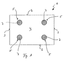
- An insulation element 1 shown in FIG. 1 is a cuboid insulation plate trained and consists of fiber material, namely rock wool.
- the insulation element 1 is produced in a manner known per se and has two parallel to one another extending side surfaces 2 and two perpendicular to the side surfaces 2 arranged narrow sides 3. Furthermore, the insulation element 1 has two large surfaces 4, of which only one can be seen in FIG. 1 and which both are aligned parallel to each other.
- the insulation element 1 has four markings 5, which on the one hand are formed as depressions in the large surface 4 are and on the other hand form a template that the arrangement of Specify insulation holders 6 ( Figure 3).
- construction adhesive there is a thin layer of construction adhesive in the recessed markings arranged.
- a thin layer of basic plaster can also be provided be, the base plaster or the construction adhesive completely or partially can fill out. If necessary, the construction adhesive or the base plaster Supplements or plastics that have increased moisture retention serve.
- FIG. 3 shows the arrangement of several insulation elements 1 on a facade 8 shown.
- the insulation elements 1 are in association with butt joints arranged.
- the insulation elements 1 with the Connect facade 8 having structure, the insulation 1 glued to the facade 8 by means of an adhesive layer 9.
- the insulation holder 6, which have insulation plate 10, in the as Wells formed markings 5, previously corresponding Bores are drilled in which the insulation holder 6 is anchored become.
- the plaster layer 11 is applied to the insulation elements 1.
- the plaster layer 11 usually consists of a base plaster and a Finishing plaster.
- the adhesive layer 9 is shown over the entire surface.
- the insulation elements 1 with at least about 60% of their area on the Glue facade 8.
- These are insulation elements 1 which are used for Picking up a plaster layer 11 are suitable and thus rigid.
- Mineral wool insulation boards with a high bulk density and sufficient shear rigidity is used.
- the number of insulation holders 6 depends on the type of insulation material of the insulation elements 1 and / or depending on the height of the building with the expected one Wind suction load and the design of the insulation holder 6 with regard Diameter and arrangement.
- the second embodiment of the insulating element shown in Figures 4 to 6 1 essentially corresponds to the embodiment according to FIGS. 1 through 3. It will therefore be used below for matching construction elements the reference numerals used in Figures 1 to 3 used.
- closure body 12 are used.
- These closure bodies consist of mineral fibers and can be increased compared to the bulk density of the insulation element Show bulk density.
- the closure body 12 are attached in the wells, so that the plaster layer 11 is even in the area of the closure body 12 Forms layer and does not lead to the closure body 12 falling out.
- closure bodies 12 are also in the region of their Shell surface via an additional adhesive layer 13 with the walls of the Glued wells. Furthermore, the closure body 12, for example be elasticized by flexing.
- FIG. 6 shows in detail the fastening of the insulation board 1 by means of the insulation holder 6 on the facade 8.
- Each insulation holder 6 consists of a die Insulation board 1 through dowels 14 and one through the dowels 14 Screw 15.
- the dowel 14 has its arranged in the recess End a collar 16, which rests on a pressure plate 17.
- the pressure plate 17 has an outer contour that matches the inner contour of the depression matches.
- the pressure plate 17 is used for uniform pressure introduction in the insulation plate 1.
- the diameter of the pressure plate 17 is particularly dependent on the strength of the insulation board 1.
Abstract
Description
Die Erfindung betrifft ein Dämmelement für die Dämmung von Außenfassaden an Gebäuden, insbesondere als Bestandteil eines Wärmedämmverbundsystems, welches plattenförmig ausgebildet und zur Aufnahme eines Putzauftrags geeignet und mittels Halteelementen an der Außenfassade befestigbar ist.The invention relates to an insulation element for the insulation of external facades on buildings, especially as part of a composite thermal insulation system, which is plate-shaped and for receiving a plaster job suitable and attachable to the outer facade using retaining elements is.
Für die Dämmung von Außenfassaden an Gebäuden werden zumeist plattenförmige Dämmstoffe aus Faserdämmstoffen, Polystyrol-, Phenolharz-, Polyurethan-Hartschaum, Schaumglas oder leichtem Porenbeton verwendet. Diese Dämmstoffe unterscheiden sich in erster Linie durch ihre mechanischen Eigenschaften. Die Dämmstoffe werden in Dämmstoffschichten auf der Außenfassade angeordnet und mit hinterlüfteten Verkleidungen bzw. Abdeckungen aus beispielsweise Blechen, Faserzementplatten, Holz, Holzwerkstoffen, Natur- und künstlichen Steinen, Beton oder dergleichen überdeckt. Die Dämmstoffe derartiger Dämmstoffschichten werden nur gering durch ihr Eigengewicht und unwesentlich durch Windsog belastet. Es besteht daher die Möglichkeit, derartige Dämmstoffschichten aus flexiblen und leicht kompressiblen Faserdämmstoffen niedriger bis mittlerer Rohdichte auszubilden.Slab-shaped are mostly used for the insulation of external facades on buildings Insulation materials made of fiber insulation materials, polystyrene, phenolic resin, rigid polyurethane foam, Foam glass or light aerated concrete is used. This Insulation materials differ primarily in their mechanical properties. The insulation materials are in layers of insulation on the outer facade arranged and with ventilated cladding or covers for example sheets, fiber cement panels, wood, wood materials, natural and artificial stones, concrete or the like covered. The insulation of such Insulation layers become low due to their own weight and are insignificant burdened by wind suction. There is therefore the possibility of such Insulation layers made of flexible and easily compressible fiber insulation materials train low to medium bulk density.
Alternativ werden Außenfassaden von Gebäuden mit sogenannten Wärmedämmverbundsystemen gedämmt. Bei diesen Wärmedämmverbundsystemen werden Putzschichten direkt auf die Dämmplatten aufgebracht, so daß die Dämmschicht durch Eigengewicht, Windsog und die durch die Putzbewegungen hervorgerufenen Zwängungsspannungen belastet ist. Bei diesen Wärmedämmverbundsystemen haben sich Dämmstoffplatten bewährt, die in sich steif ausgebildet sind.Alternatively, external facades of buildings with so-called thermal insulation composite systems insulated. With these thermal insulation composite systems plaster layers are applied directly to the insulation boards, so that the Insulation layer due to its own weight, wind suction and the cleaning movements induced constraint stresses. With these thermal insulation composite systems have proven insulation boards that are stiff in themselves are trained.
In jedem Fall werden die Dämmelemente im allgemeinen im Verband verlegt und auf der Fassade mit Hilfe von Dämmstofftellern gehalten und mittels Dübeln in der Fassade verankert. Die Dämmstoffteller sind hierbei mit den Dübeln über einen Schaft verbunden und bilden eine Einheit. Nachfolgend wird die Einheit aus Dämmstoffteller und Dübeln als Dämmstoffhalter bezeichnet.In any case, the insulation elements are generally laid in a group and held on the facade with the help of insulation plates and dowels anchored in the facade. The insulation plate is here with the dowels connected by a shaft and form a unit. Below is the Unit made of insulation plate and dowels called insulation holder.
Im wesentlichen werden die Dämmelemente bei der üblichen Verarbeitungsweise nur mit Hilfe der Dämmstoffhalter fixiert. In diesen Fällen spricht man von einer mechanischen Befestigung. Bei der Montage der Dämmelemente werden die Dämmstoffhalter fest an den Dämmstoff gepreßt, um durch den Formschluß eine entsprechende Kraftübertragung zu ermöglichen. Kompressible Dämmelemente werden an diesen Stellen deutlich zusammengedrückt und dehnen sich in den Bereichen zwischen den Dämmstoffhaltern in ungünstigen Fällen sogar aus. Um einen notwendigen Hinterlüftungsspalt, der in der Regel eine Tiefe von 2 bis 4 cm aufweist, nicht zu verengen, müssen die Dämmelemente insbesondere an den Rändern heruntergedrückt werden. Darüber hinaus weisen überstehende Ränder bei noch ungeschützter Dämmschicht Angriffsflächen für Regen auf. Um diese Nachteile zu vermeiden, ist es aus dem Stand der Technik bekannt, die Dämmstoffhalter im Stoßbereich benachbarter Dämmelemente anzuordnen. Gleichzeitig sind aber auch Dämmstoffhalter notwendig, die im Bereich der großen Oberflächen eines Dämmelementes angeordnet sind. Eine derartige, in der Regel willkürlich gewählte Anordnung von Dämmstoffhaltern führt aber zu einem sehr großen Bedarf an Dämmstoffhaltern, wenngleich bei dieser Vorgehensweise Unebenheiten der Fassadenoberfläche im Bereich der Dämmelemente ausgeglichen werden können.Essentially, the insulation elements are used in the usual way of processing only fixed with the help of the insulation holder. In these cases one speaks of a mechanical attachment. When installing the insulation elements the insulation holder is pressed firmly against the insulation in order to close it to enable a corresponding power transmission. Compressible Insulation elements are clearly compressed at these points and stretch in the areas between the insulation holders in unfavorable Cases even out. To a necessary ventilation gap, which is usually has a depth of 2 to 4 cm, not to narrow, the insulation elements especially at the edges. Furthermore have protruding edges when the insulation layer is still unprotected for rain on. To avoid these disadvantages, it is from the State of the art, the insulation holder in the joint area adjacent Arrange insulation elements. At the same time, insulation holders are also necessary which are arranged in the area of the large surfaces of an insulation element are. Such an, as a rule, arbitrarily chosen arrangement of Insulation holders result in a very high demand for insulation holders, although with this procedure, unevenness of the facade surface can be compensated in the area of the insulation elements.
Neben der voranstehend beschriebenen mechanischen Befestigung von Dämmelementen auf Außenfassaden von Gebäuden ist es auch bekannt, die Dämmelemente auf die Außenfassade aufzukleben. Entsprechend verwendete Klebemittel vermögen bei entsprechenden, vollflächigen, zumindest aber linienförmigem Auftrag, die Dämmstoffelemente auszusteifen. Durch die vorherige Fixierung der Dämmelemente mittels dieser Klebemittel ist dann auch die Montage der zusätzlich notwendigen Dämmstoffhalter vereinfacht. Insbesondere lassen sich bei dieser Vorgehensweise die notwendigen Dübellöcher schneller bohren bzw. die Dämmstoffhalter rationeller setzen.In addition to the mechanical fastening of insulation elements described above on exterior facades of buildings it is also known that Glue insulation elements to the outer facade. Used accordingly Adhesives are suitable for corresponding full-surface, or at least linear ones Order to stiffen the insulation elements. Through the previous one Fixing the insulation elements with these adhesives is then also Installation of the additionally required insulation holder simplified. In particular the necessary dowel holes can be made with this procedure drill faster or set the insulation holder more efficiently.
Vorzugsweise werden solche Dämmstoffhalter verwendet, deren Dämmstoffteller einen Durchmesser von ca. 90 mm aufweisen.Such insulation holders are preferably used, their insulation plates have a diameter of approx. 90 mm.
Werden die Dämmstoffhalter im Fugenbereich zwischen benachbarten Dämmelementen angeordnet, so kann kaum eine wesentliche Haltewirkung durch die Dämmstoffhalter erzielt werden. Es ist daher - wie bereits ausgeführt - erforderlich, zumindest einen Dämmstoffteller im Bereich der außenliegenden großen Oberfläche des Dämmelements anzuordnen. Nur dieser innerhalb eines Dämmstoffelementes angeordnete Dämmstoffhalter erreicht den optimalen Formschluß, der beispielsweise einer bei Windbelastung auftretenden Verformung entgegenwirken kann. Hierbei ist die erforderliche Anzahl der Dämmstoffhalter pro Dämmstoffelement u.a. abhängig von der Eigenlast des Dämmelements bzw. der darauf befestigten Putzschichten, ihren Abmessungen, dem Strömungswiderstand und der Windsog-Belastung, also der Lage und Höhe der zu dämmenden Wandfläche.If the insulation material holder in the joint area between adjacent insulation elements arranged, so can hardly an essential holding effect the insulation holder can be achieved. As already stated, it is therefore necessary at least one insulation plate in the area of the outside arrange large surface of the insulation element. Only this within one Insulation element holder arranged achieves the optimal Positive locking, for example of a deformation occurring during wind loads can counteract. Here is the required number of insulation holders per insulation element depending on the dead weight of the insulation element or the plaster layers attached to it, their dimensions, the flow resistance and the wind suction load, i.e. the position and height the wall surface to be insulated.
Hierbei ist bekannt, daß luftdurchlässige Faserdämmstoffe nur geringe Strömungswiderstände aufweisen. Dämmelemente aus Steinwolle weisen zudem eine ausreichende Steifigkeit und Punktbelastbarkeit auf. Die Steifigkeit und Punktbelastbarkeit steigt mit zunehmender Dicke der Dämmelemente. Mit zunehmender Dicke erhöhen sich aber auch die Seitenflächen der Dämmelemente und die über diese Flächen übertragbaren Reibungskräfte. Bei dichtgestoßenen Fugen bleiben die Dämmelemente relativ zueinander in einer stabilen Position. Aus den voranstehenden Vorteilen der Dämmelemente aus Steinwolle ergibt sich der weitere Vorteil, daß für die Befestigung von Dämmelementen aus Steinwolle im Bereich von Außenfassaden an Gebäuden nur eine geringe Anzahl von Dämmstoffhaltern notwendig ist. Eine wesentliche Reduzierung der Dämmstoffhalter kann aber nur dann erzielt werden, wenn die Dämmstoffhalter an einer bestimmten Position der Dämmelemente gesetzt sind. It is known that air-permeable fiber insulation materials have only low flow resistances exhibit. Stone wool insulation elements also feature sufficient rigidity and point load capacity. The rigidity and Point load capacity increases with increasing thickness of the insulation elements. With increasing The side surfaces of the insulation elements also increase in thickness and the friction forces that can be transmitted over these surfaces. With tightly knocked The insulation elements remain stable in relation to each other Position. From the above advantages of stone wool insulation there is the further advantage that for fastening insulation elements made of stone wool in the area of external facades on buildings only a small one Number of insulation holders is necessary. A substantial reduction in Insulation holder can only be achieved if the insulation holder are set at a certain position of the insulation elements.
Es ist ohne weiteres ersichtlich, daß es für den Anwender derartiger Dämmelemente erstrebenswert ist, eine möglichst geringe Anzahl von Dämmstoffhaltern zu verwenden. Hierdurch werden einerseits die Materialkosten und andererseits die Montagezeiten und somit auch die Arbeitskosten reduziert. Hieraus ergeben sich wirtschalftliche Vorteile für die Hersteller derartiger Dämmelemente, da Dämmelemente dann besser vermarktet werden können, wenn einerseits derartige Dämmelemente in einfacher und zeitlich begrenzter Weise verarbeitet werden können und andererseits die zur Verarbeitung notwendigen Hilfsstoffe mengenmäßig begrenzt werden können.It is readily apparent that it is for the user of such insulation elements It is desirable to have the smallest possible number of insulation holders to use. As a result, the material costs on the one hand and on the other assembly times and thus labor costs are reduced. Out of this there are economic advantages for the manufacturers of such insulation elements, because insulation elements can be marketed better if on the one hand, such insulation elements in a simple and time-limited manner can be processed and on the other hand the necessary for processing Auxiliaries can be limited in quantity.
Aus Sicherheitsgründen, aber auch um den sich hieraus ergebenden wirtschaftlichen Vorteil umsetzen zu können, ist der Hersteller derartiger Dämm elemente daran interessiert, daß die verarbeitenden Unternehmen, die Dämmelemente entsprechend den Vorgaben befestigen. Dementsprechend geben die Hersteller Anleitungen und Anweisungen für die wünschenswerte und erforderliche Verarbeitung derartiger Dämmelemente aus. In der Praxis hat sich aber gezeigt, daß die mit der Verarbeitung derartiger Dämmelemente beauftragten Personen entsprechende Anleitungen und Anweisungen in der Regel nicht zur Kenntnis nehmen, in den weitaus meisten Fällen aber zumindest nicht in richtiger Weise umsetzen. Üblicherweise werden die Dämmstoffhalter relativ frei, d.h. ohne Regelmäßigkeit und Vorgaben gesetzt. Hierbei tritt auch das Problem auf, daß die Dämmung von Fassaden von Gerüsten im Bereich mehrerer Gewerke gleichzeitig erfolgt, so daß mitunter keine Abstimmung zwischen den Gewerken vorhanden ist. Durch das sofortige Abdecken der Dämmelemente mit dem Grundputz ist die unregelmäßige Anordnung der Dämmstoffhalter erst am fertigen Werk zu beobachten, wenn bestimmte Einflüsse auftreten. Die Folgen einer unregelmäßigen, nicht den Anweisungen entsprechenden Anordnung der Dämmstoffhalter sind zu diesem Zeitpunkt nicht mehr korrigierbar, ohne daß große Rückbaumaßnahmen verbunden mit hohen Kosten notwendig werden. Beispielsweise können sich die Dämmstoffteller bei partiell feuchten Putzschichten auf der fertigen Oberfläche des Wärmedämmverbundsystems abzeichnen. Die Materialstärke und die Farbe der Putzschicht beeinflußt dann den Grad der Beeinträchtigung. Soweit derartige Beeinträchtigungen nicht vermeidbar sind, sollte zumindest ein regelmäßiges Raster vorhanden sein, das beim Betrachter zu dem optischen Ergebnis führt, die Abzeichnung der Dämmstoffteller sei bewußt gewollt.For security reasons, but also for the resulting economic The manufacturer of this type of insulation is able to implement the advantage elements interested in the manufacturing companies, the insulation elements fasten according to the specifications. Give accordingly the manufacturers instructions and instructions for the desirable and necessary Processing of such insulation elements. In practice it has but showed that those commissioned with the processing of such insulation elements Instructions and instructions corresponding to people as a rule not take note, but in most cases at least not implement in the right way. The insulation holders are usually relative free, i.e. set without regularity and specifications. This also occurs Problem on that the insulation of facades of scaffolding in the area of several Trades are carried out simultaneously, so that sometimes no coordination between is available to the trades. By immediately covering the insulation elements with the base plaster is the irregular arrangement of the insulation holder only to be observed in the finished work when certain influences occur. The consequences of an irregular, not according to the instructions The arrangement of the insulation holders can no longer be corrected at this point, without large dismantling measures associated with high costs become. For example, the insulation plate at partial damp plaster layers on the finished surface of the thermal insulation composite system sign off. The material thickness and the color of the plaster layer affects then the degree of impairment. So much for such impairments are unavoidable, there should at least be a regular grid that leads to the visual result for the viewer, the mark the insulation plate is deliberately wanted.
Aus der FR 2 694 319 A1 ist beispielsweise ein Dämmelement aus Polystyrol bekannt, in welches im Bereich von Bohrungen zur Aufnahme von Schrauben x-förmige Versteifungselemente eingelegt werden. Durch die steife Ausgestaltung von Polystyrolplatten ist es möglich, derartige Versteifungselemente während des Aufschäumens des Polystyrols zu ummanteln und in das Dämmelement zu integrieren. Diese Herstellungsweise ist aber sehr kostenintensiv und führt bei ungenauer Verfahrensführung zu einem hohen Ausschuß an nicht verwertbaren Dämmelementen. Darüberhinaus sind derartige Dämmelemente mit eingelegten Versteifuungslementen nicht oder nur in sehr begrenztem Masse an die Einbaubedingungen anpassbar. Ein Zuschneiden der Dämmelemente im Bereich der Versteifungselemente ist nahezu ausgeschlossen. Darüber hinaus wird durch die Versteifungselemente die Anzahl der einbringbaren Bohrungen zur Aufnahme der Schrauben beschränkt.FR 2 694 319 A1, for example, is an insulating element made of polystyrene known in which in the area of holes for receiving screws x-shaped stiffening elements are inserted. Due to the rigid design of polystyrene plates it is possible to use such stiffening elements during of the foaming of the polystyrene and encased in the insulation element to integrate. However, this method of production is very expensive and does not lead to a high committee if the procedure is imprecise usable insulation elements. In addition, such insulation elements with inserted stiffening elements, or only to a very limited extent adaptable to the installation conditions. Cutting the insulation elements in the area of the stiffening elements is almost impossible. Furthermore is the number of holes that can be inserted through the stiffening elements limited to accommodate the screws.
Um derartige Nachteile zu vermeiden, liegt der Erfindung die Aufgabe zugrunde, ein Dämmelement derart weiterzuentwickeln, daß die Verarbeitung bei der Fassadendämmung wesentlich vereinfacht wird.In order to avoid such disadvantages, the object of the invention is to further develop an insulating element in such a way that the processing in the facade insulation is considerably simplified.
Die Lösung dieser Aufgabenstellung sieht bei einem gattungsgemäßen Dämmelement vor, daß das Dämmelement aus mit Bindemitteln gebundenen Mineralfasern besteht und zumindest auf einer großen Oberfläche Markierungen für die Anordnung der Dämmstoffhalter aufweist ist, wobei eine der Anzahl der notwendigen Dämmstoffhalter entsprechende Anzahl von Markierungen voegesehen ist, die beabstandet zu den Rändern angeordnet sind. The solution to this problem provides for a generic insulation element that the insulation element consists of mineral fibers bonded with binders and has markings for the arrangement of the insulation holder at least on a large surface, with a number of markings corresponding to the number of insulation holders required being provided are spaced from the edges.
Ein erfindungsgemäß ausgebildetes Dämmelement weist somit Markierungen auf, die in ihrer Anzahl mit der Anzahl der zu setzenden Dämmstoffhalter übereinstimmt. Den verarbeitenden Personen wird somit ein Dämmelement zur Verfügung gestellt, das sowohl die Anzahl als auch die Lage der Dämmstoffhalter bei ordnungsgemäßer Verarbeitung vorgibt. Die voranstehend beschriebenen Nachteile bei willkürlichem Setzen der Dämmstoffhalter werden daher im wesentlichen vermieden. Darüber hinaus besteht das Dämmelement aus Mineralfasern, die für die Wärmedämmung insbesondere im Fassadenbereich besonders geeignet sind und sich leicht verarbeiten, insbesondere an die Gegebenheiten des zu dämmenden Gebäudes anpassen lassen.An insulation element designed according to the invention thus has markings which corresponds in number to the number of insulation holders to be placed. The processing person is thus an insulation element Provided both the number and the location of the insulation holder if processed correctly. The ones described above Disadvantages with arbitrary setting of the insulation holder are therefore in substantially avoided. In addition, the insulation element consists of mineral fibers, those for thermal insulation especially in the facade area are suitable and easy to work with, especially given the circumstances of the building to be insulated.
Die Markierungen sind vorzugsweise als Farbauftrag ausgebildet, da sich diese Markierungen ohne großen technischen Aufwand während der Herstellung derartiger Dämmelemente aufbringen lassen. Alternativ kann vorgesehen sein, daß die Markierungen in die Oberfläche durch lokale Erwärmung eingebrannt sind. Hierbei wird während der Herstellung der Dämmelemente zumindest eine Oberfläche lokal erwärmt, wodurch das in den Dämmelementen enthaltene Bindemittel insoweit reagiert, daß sich ein Farbunterschied zwischen der erwärmten Stelle und dem übrigen Bereich der Oberfläche abzeichnet.The markings are preferably designed as a paint application, since these Markings without great technical effort during the production of such Have insulation elements applied. Alternatively, it can be provided that the markings are burned into the surface by local heating are. At least one is used during the manufacture of the insulation elements Surface heated locally, which means that the contained in the insulation elements Binder reacts to the extent that there is a color difference between the heated Spot and the rest of the surface.
Demzufolge ist es gemäß der Erfindung vorgesehen, daß das Dämmelement aus mit Bindemitteln gebundenen Steinwollefasern besteht.Accordingly, it is provided according to the invention that the insulating element consists of rock wool fibers bound with binders.
Die Markierungen sind insbesondere regelmäßig, vorzugsweise punkt- oder achsensymmetrisch angeordnet.The markings are particularly regular, preferably point or axially symmetrical.
Nach einem weiteren Merkmal der Erfindung ist vorgesehen, daß die Markierungen in Abhängigkeit der Größe und Lage sowie weiterer geometrischer Eigenschaften, insbesondere der Dicke des Dämmelements angeordnet sind. Bei der erfindungsgemäßen Ausgestaltung des Dämmelements wird die erforderliche bzw. beabsichtigte Anordnung der Halteteller nach Größe und Lage, unter Umständen auch in Abhängigkeit von der Dicke der Dämmplatte von vornherein festgelegt. Wenn sich die Zahl und Anordnung der Dämmstoffhalter in Abhängigkeit von der Höhe des zu dämmenden Gebäudes ändert, sieht die erfindungsgemäße Ausgestaltung eines Dämmelements eine entsprechend differenzierte Gestaltung höhenabhängig zu montierender Dämmelement-Chargen vor.According to a further feature of the invention it is provided that the markings depending on the size and location as well as other geometric properties, in particular the thickness of the insulating element are arranged. At the design of the insulation element according to the invention becomes the required one or intended arrangement of the holding plates according to size and location, below Under certain circumstances, depending on the thickness of the insulation board from the outset fixed. If the number and arrangement of the insulation holder depends on changes from the height of the building to be insulated sees the invention Design of an insulation element a correspondingly differentiated Design of height-dependent insulation element batches in front.
Die Markierungen können punkt- und/oder kreuzförmig ausgebildet sein, um ein genaues Setzen der Dämmstoffhalter zu ermöglichen.The markings can be point-shaped and / or cross-shaped in order to to enable precise placement of the insulation holder.
Nach einem weiteren Merkmal der Erfindung ist vorgesehen, daß die Markierungen eine Größe aufweisen, die mit der flächenmäßigen Größe der Dämmstoffhalter, insbesondere der Dämmstoffteller übereinstimmt.According to a further feature of the invention it is provided that the markings have a size that corresponds to the surface area of the insulation holder, especially the insulation plate matches.
Demzufolge sind die Markierungen als optisch wirksame Symbole ausgebildet, die mit Hilfe von Farben oder durch Einbrennen hergestellt werden. Zusätzlich zu den beispielsweise punkt- oder kreuzförmig ausgebildeten Markierungen können Angaben über Art und Form der Dämmstoffhalter aufgebracht sein. Die erforderliche Größe der Dämmstoffteller kann durch eine entsprechende Ausgestaltung der Markierung vorgegeben werden, so daß nach der Montage der Dämmelemente eine schnelle und einfache Sichtkontrolle der ordnungsgemäß verwendeten Dämmstoffhalter möglich ist.As a result, the markings are designed as optically effective symbols, which are made with the help of colors or by baking. In addition to the markings, for example in the form of points or crosses information about the type and shape of the insulation holder can be applied. The required size of the insulation plate can be designed accordingly the marking can be specified so that after mounting the Insulation elements a quick and easy visual inspection of the properly insulation holder used is possible.
Es ist nach einem weiteren Merkmal der Erfindung vorgesehen, daß die Markierungen durch linien- und/oder gitterlinienförmige Elemente miteinander verbunden sind.It is provided according to a further feature of the invention that the markings connected to one another by line-shaped and / or grid-line-shaped elements are.
Weiterhin hat es sich als vorteilhaft erwiesen, die Markierungen in Vertiefungen im Dämmelement anzuordnen und/oder die Markierungen als Vertiefungen auszubilden. Die Dicke der Dämmstoffteller verringert die auf Putzträgerplatten aufbringbare Putzschicht, was bei der Tendenz zu immer dünner werdenden Grund- und Oberputzschichten dazu führt, daß ein Verstärkungsgewebe nur noch unvollständig eingebettet wird. Hierdurch wird ein derart ausgebildetes Wärmedämmverbundsystem schadenanfälliger. Es ist daher sinnvoll, die Dämmstoffteller versenkt in die Oberfläche der Dämmelemente einzubringen. Vorzugsweise sind die Vertiefungen mechanisch herausgearbeitet bzw. bei thermoplastischen Dämmstoffen durch lokale Erhitzung mit den dadurch verbundenen Schrumpf- und Verdichtungsvorgängen hergestellt. Die Vertiefungen können zusätzlich optisch hervorgehoben sein.Furthermore, it has proven advantageous to use the markings in depressions to be arranged in the insulation element and / or the markings as depressions to train. The thickness of the insulation plate reduces that on the plaster base applied plaster layer, which tends to become thinner Base and finishing layers result in a reinforcing fabric only is still incompletely embedded. As a result, such is formed Thermal insulation composite system more susceptible to damage. It therefore makes sense to Insert the insulation plate sunk into the surface of the insulation elements. The depressions are preferably worked out mechanically or at thermoplastic insulation materials by local heating with the associated Shrinking and compaction processes. The wells can also be highlighted.
In einer weiteren erfindungsgemäßen Ausgestaltung sind in den Vertiefungen dünne Schichten Grundputz, Baukleber oder dergleichen hygrothermische Eigenschaften aufweisende Materialien angeordnet. Diese Materialien haben im wesentlichen die gleichen hygrothermischen Eigenschaften, wie der aufzutragende Grundputz. Ergänzend können die in den Vertiefungen angeordneten Materialien Zuschläge, insbesondere Kunststoffe aufweisen, die Feuchte speichernde Eigenschaften aufweisen.In a further embodiment according to the invention are in the depressions thin layers of base plaster, construction adhesive or similar hygrothermal properties having arranged materials. These materials have in essentially the same hygrothermal properties as the one to be applied Basic plaster. In addition, those arranged in the recesses can be used Materials have aggregates, especially plastics that store moisture Have properties.
Entsprechend der erforderlichen Anzahl von Dämmstoffhaltern, der Form und dem Durchmesser sowie der gewünschten Versenkungstiefe der Dämmstoffteller werden oberflächennahe Bereiche aus dem Dämmelement mit Hilfe von beispielsweise Kernbohrern herausgelöst. Die nunmehr eine Ausnehmung aufweisenden Bereiche des Dämmelementes weisen eine höhere Kompressibilität auf, da die mittragende Wirkung der Randbereiche wegfällt. Der Dämmstoffhalter wird daher beim Anziehen seiner Kernschraube oder beim Einschlagen seines Schlagbolzens tiefer in das Dämmelement gezogen bzw. gedrückt.According to the required number of insulation holders, the shape and the diameter and the desired recess depth of the insulation plate areas close to the surface are made from the insulation element with the help of for example, core drills. The now having a recess Areas of the insulation element have a higher compressibility on, since the supporting effect of the edge areas is eliminated. The insulation holder is therefore when tightening his core screw or when driving in its firing pin is pulled or pressed deeper into the insulation element.
Um diese verbesserte Verbindung weiterzubilden ist vorgesehen, dass die Bereich in und um den Vertiefungen elastifiziert werden. Hierzu können diese Bereich beispielsweise einer ein- oder mehrmaligen Druckbelastung ausgesetzt werden, um den durch das Bindemittel gegebenen Verbund der Mineralfasern aufzulösen. Durch eine höhere Elastizität in den Vertiefungen können die Dämmstoffhalter mit größerer Versenkungstiefe eingebaut werden. In order to further develop this improved connection, it is provided that the area be elasticized in and around the depressions. You can do this in this area for example exposed to one or more pressure loads the composite of mineral fibers given by the binder dissolve. Due to a higher elasticity in the recesses, the Insulation holder with greater countersink depth can be installed.
Gemäß einer Weiterbildung der Erfindung werden die Markierungen von vornherein mit einer im Vergleich zur Materialstärke des Dämmelements großen Tiefe aus dem Dämmelement herausgearbeitet. Um die Wärmedämmeigenschaften eines derartigen Dämmelementes nicht nachteilig zu verändern ist vorgesehen, dass die Vertiefungen mit einem Verschlußkörper verschließbar sind. Die Verschlußkörper können aus Mineralfasern oder einem anderen kompressiblen Dämmstoff ausgebildet sein.According to a development of the invention, the markings are made from the outset with a large compared to the material thickness of the insulation element Depth worked out of the insulation element. To the thermal insulation properties of such an insulation element is not disadvantageously changed provided that the wells can be closed with a closure body are. The closure bodies can be made of mineral fibers or another compressible Insulation material should be formed.
Die Auszugskraft des Verschlußkörpers wird durch die erreichbaren Reibungskräfte zwischen dem Verschlußkörper und dem Dämmelement erzielt. Sie kann durch ein Verkleben des Verschlußkörpers in der Vertiefung deutlich erhöht bzw. auf das Niveau der Querzugfestigkeit der benachbarten Dämmstoffbereiche gebracht werden.The pull-out force of the closure body is determined by the frictional forces that can be achieved achieved between the closure body and the insulating element. she can significantly increased by gluing the closure body in the recess or to the level of the transverse tensile strength of the neighboring insulation areas to be brought.
Die erfindungsgemäße Ausgestaltung eines Dämmelements aus Mineralfasern mit Vertiefungen stellt auch insoweit eine sehr wirtschaftlich Wärmedämmung dar, weil bei entsprechender Tiefe der Vertiefungen die Länge der Dämmstoffhalter unabhängig von der Materialstärke des Dämmelements ausgebildet werden kann. Die Vertiefungen werden zu diesem Zweck zumindest in ihrer Tiefe aber auch hinsichtlich ihrer Form auf die die Form und die Länge der überlicherweise verwendeten Dämmstoffhalter einer bestimmten Ausgestaltung und Länge abgestellt. Dadurch wird auch die Beanspruchung des Schaftes des Dämmstoffhalters geringer bzw. der Schaft braucht bei größerer Dämmstoffdicke nicht dicker dimensioniert zu werden. Hierdurch können Materialkosten eingesparrt und Wärmebrücken reduziert werden.The inventive design of an insulating element made of mineral fibers with recesses also provides very economical thermal insulation because the depth of the recesses means the length of the insulation holder regardless of the material thickness of the insulation element can. For this purpose, the wells are at least in depth but also in terms of their shape to which the shape and length of the usually used insulation holder of a certain design and Length turned off. This also stresses the shaft of the Insulation holder less or the shaft needs more insulation not to be made thicker. This can save material costs and thermal bridges can be reduced.
Nach einem weiteren Merkmal ist vorgesehen, daß die Materialien zumindest nach ihrer Aushärtung eine steife Schicht bilden, um eine gleichmäßige Kraftübertragung auf das Dämmelement zu gewährleisten. Des weiteren wird durch diese Ausgstaltung das durch den Dämmstoffteller verringerte Grundputzvolumen kompensiert und die durch die Dämmstoffhalter bewirkten optischen Beeinträchtigungen der geputzten Außenfläche (Oberputz) im feuchten Zustand deutlich reduziert bzw. aufgehoben.According to a further feature it is provided that the materials at least Once hardened, form a stiff layer to create an even layer To ensure power transmission to the insulation element. Furthermore, due to this design, the volume of basic plaster reduced by the insulation plate compensated and the optical effects caused by the insulation holder Impairment of the cleaned outer surface (finishing plaster) in the damp Condition significantly reduced or canceled.
Schließlich ist bei einem weiteren Merkmal der Erfindung vorgesehen, daß das Dämmelement eine Kaschierung, insbesondere in Form eines Glasvlieses aufweist, wobei die Markierungen auf der Kaschierung angeordnet sind.Finally, it is provided in a further feature of the invention that the Insulation element has a lamination, in particular in the form of a glass fleece, the markings being arranged on the lamination.
Weitere Merkmale und Vorteile der Erfindung ergeben sich aus der nachfolgenden Beschreibung der zugehörigen Ausführungsform eines erfindungsgemäßen Dämmelementes. In der Zeichnung zeigen:
- Figur 1
- ein Dämmelement in Ansicht;
- Figur 2
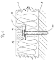
- einen Ausschnitt des Dämmelementes gemäß Figur 1 in geschnittener Seitenansicht;
Figur 3- die Anordnung mehrerer Dämmelemente gemäß Figur 1 im Bereich einer Fassade als Wärmedämmverbundsystem;
Figur 4- eine zweite Ausführungsform eines Dämmelementes in Ansicht;
Figur 5- das
Dämmelement gemäß Figur 4 in geschnitten dargestellter Seitenansicht und - Figur 6
- die Anordnung eines Dämmelementes gemäß
den Figuren 4 und 5 im Bereich einer Fassade als Wärmedämmverbundsystem.
- Figure 1
- an insulation element in view;
- Figure 2
- a section of the insulating element according to Figure 1 in a sectional side view;
- Figure 3
- the arrangement of several insulation elements according to Figure 1 in the area of a facade as a composite thermal insulation system;
- Figure 4
- a second embodiment of an insulation element in view;
- Figure 5
- the insulation element according to Figure 4 in a sectional side view and
- Figure 6
- the arrangement of an insulation element according to Figures 4 and 5 in the region of a facade as a composite thermal insulation system.
Ein in Figur 1 dargestelltes Dämmelement 1 ist als quaderförmige Dämmplatte
ausgebildet und besteht aus Fasermaterial, nämlich Steinwolle. Das Dämmelement
1 ist in an sich bekannter Weise hergestellt und weist zwei parallel zueinander
verlaufende Seitenflächen 2 sowie zwei rechtwinklig zu den Seitenflächen
2 angeordnete Schmalseiten 3 auf. Ferner hat das Dämmelement 1 zwei
große Oberflächen 4, von denen in Figur 1 lediglich eine erkennbar ist und die
beide parallel zueinander ausgerichtet sind.An insulation element 1 shown in FIG. 1 is a cuboid insulation plate
trained and consists of fiber material, namely rock wool. The insulation element
1 is produced in a manner known per se and has two parallel to one another
extending side surfaces 2 and two perpendicular to the side surfaces
2 arranged
Im Bereich der großen Oberfläche 4 weist das Dämmelement 1 vier Markierungen
5 auf, die einerseits als Vertiefungen in der großen Oberfläche 4 ausgebildet
sind und andererseits eine Schablone bilden, die die Anordnung von
Dämmstoffhaltern 6 (Figur 3) vorgeben.In the area of the
In den vertieft ausgebildeten Markierungen ist eine dünne Schicht Baukleber angeordnet. Alternativ kann auch eine dünne Schicht Grundputz vorgesehen sein, wobei der Grundputz bzw. der Baukleber die Vertiefung ganz oder teilweise ausfüllen kann. Gegebenenfalls kann der Baukleber bzw. der Grundputz Zuschläge oder Kunststoffe aufweisen, die einer erhöhten Feuchtespeicherung dienen.There is a thin layer of construction adhesive in the recessed markings arranged. Alternatively, a thin layer of basic plaster can also be provided be, the base plaster or the construction adhesive completely or partially can fill out. If necessary, the construction adhesive or the base plaster Supplements or plastics that have increased moisture retention serve.
In Figur 3 ist die Anordnung mehrerer Dämmelemente 1 an einer Fassade 8
dargestellt. Die Dämmelemente 1 sind im Verband mit dichtgestoßenen Fugen
angeordnet. Bevor die Dämmstoffhalter 6 die Dämmelemente 1 mit dem die
Fassade 8 aufweisenden Bauwerk verbinden, werden die Dämmelemente 1
mittels einer Kleberschicht 9 auf der Fassade 8 aufgeklebt. Anschließend werden
die Dämmstoffhalter 6, welche Dämmstoffteller 10 aufweisen, in die als
Vertiefungen ausgebildeten Markierungen 5 gesetzt, wobei zuvor entsprechende
Bohrungen niedergebracht werden, in denen die Dämmstoffhalter 6 verankert
werden.FIG. 3 shows the arrangement of several insulation elements 1 on a
Abschließend wird eine Putzschicht 11 auf die Dämmelemente 1 aufgetragen. Die Putzschicht 11 besteht in der Regel aus einem Grundputz und einem Oberputz.Finally, a plaster layer 11 is applied to the insulation elements 1. The plaster layer 11 usually consists of a base plaster and a Finishing plaster.
In Figur 3 ist die Kleberschicht 9 vollflächig dargestellt. In der Regel ist es aber
ausreichend, die Dämmelemente 1 mit zumindest ca. 60% ihrer Fläche auf der
Fassade 8 zu verkleben. Es handelt sich hierbei um Dämmelemente 1, die zum
Aufnehmen einer Putzschicht 11 geeignet und somit steif ausgebildet sind.
Hierbei werden insbesondere Mineralwolle-Dämmplatten hoher Rohdichte und
damit ausreichender Schubsteifigkeit eingesetzt. Die Anzahl der Dämmstoffhalter
6 richtet sich nach der Art des Dämmstoffmaterials der Dämmelemente 1
und/oder in Abhängigkeit von der Höhe des Gebäudes mit der damit zu erwartenden
Windsogbelastung sowie der Ausgestaltung der Dämmstoffhalter 6 hinsichtlich
Durchmesser und Anordnung.In Figure 3, the adhesive layer 9 is shown over the entire surface. Usually it is
sufficient, the insulation elements 1 with at least about 60% of their area on the
Die in den Figuren 4 bis 6 dargestellte zweite Ausführungsform des Dämmelements 1 entspricht im wesentliche der Ausführungsform gemäß den Figuren 1 bis 3. Es werden daher nachfolgend für übereinstimmende Konstruktionselemente die in den Figuren 1 bis 3 verwendeten Bezugszeichen verwendet.The second embodiment of the insulating element shown in Figures 4 to 6 1 essentially corresponds to the embodiment according to FIGS. 1 through 3. It will therefore be used below for matching construction elements the reference numerals used in Figures 1 to 3 used.
Ein Unterschied zwischen den beiden Ausführungsformen besteht darin, daß
bei der Ausführungsform gemäß Figuren 4 bis 6 in die Vertiefungen Verschlußkörper
12 eingesetzt sind. Diese Verschlußkörper bestehen aus Mineralfasern
und können im Vergleich zur Rohdichte des Dämmelementes eine erhöhte
Rohdichte aufweisen. Über die nicht näher dargestellte Schicht Baukleber 7 in
den Vertiefungen sind die Verschlußkörper 12 in den Vertiefungen befestigt, so
daß die Putzschicht 11 auch im Bereich der Verschlußkörper 12 eine ebene
Schicht bildet und nicht zum Herausfallen der Verschlußkörper 12 führt.A difference between the two embodiments is that
in the embodiment according to Figures 4 to 6 in the
Alternativ bzw. ergänzend sind die Verschlußkörper 12 auch im Bereich ihrer
Mantelfläche über eine zusätzliche Kleberschicht 13 mit den Wandungen der
Vertiefungen verklebt. Ferner kann der Verschlußkörper 12 beispielsweise
durch Walkarbeit elastifiziert sein.As an alternative or in addition, the
Figur 6 zeigt detailliert die Befestigung der Dämmplatte 1 mittels der Dämmstoffhalter
6 an der Fassade 8. Jeder Dämmstoffhalter 6 besteht aus einem die
Dämmplatte 1 durchgreifenden Dübel 14 und einer den Dübel 14 durchgreifenden
Schraube 15. Der Dübel 14 weist an seinem in der Vertiefung angeordneten
Ende einen Kragen 16 auf, der auf einer Druckplatte 17 aufliegt. Die Druckplatte
17 weist eine Außenkontur auf, die mit der Innenkontur der Vertiefung
übereinstimmt. Die Druckplatte 17 dient der gleichmäßigen Druckeinleitung in
die Dämmplatte 1. Der Durchmesser der Druckplatte 17 ist insbesondere abhängig
von der Festigkeit der Dämmplatte 1.Figure 6 shows in detail the fastening of the insulation board 1 by means of the insulation holder
6 on the
Claims (18)
dadurch gekennzeichnet,
daß die Markierungen (5) als Farbauftrag ausgebildet sind.Insulating element according to claim 1,
characterized,
that the markings (5) are designed as a paint application.
dadurch gekennzeichnet,
daß die Markierungen (5) in die Oberfläche (4) durch lokale Erwärmung eingebracht sind.Insulating element according to claim 1,
characterized,
that the markings (5) are introduced into the surface (4) by local heating.
gekennzeichnet durch
die Ausbildung aus mit Bindemitteln gebundenen Steinwollefasern.Insulating element according to claim 1,
marked by
the formation of rock wool fibers bound with binders.
dadurch gekennzeichnet,
daß die Markierungen (5) regelmäßige, insbesondere punkt- oder achsensymmetrisch angeordnet sind. Insulating element according to claim 1,
characterized,
that the markings (5) are arranged regularly, in particular point or axisymmetrically.
dadurch gekennzeichnet,
daß die Markierungen (5) in Abhängigkeit der Größe und Lage sowie weiterer geometrischer Eigenschaften, insbesondere der Dicke des Dämmelements (1) angeordnet sind.Insulating element according to claim 1,
characterized,
that the markings (5) are arranged depending on the size and position as well as other geometric properties, in particular the thickness of the insulating element (1).
dadurch gekennzeichnet,
daß die Markierungen (5) punkt- und/oder kreuzförmig ausgebildet sind.Insulating element according to claim 1,
characterized,
that the markings (5) are point and / or cross-shaped.
dadurch gekennzeichnet,
daß die Markierungen (5) eine Größe aufweisen, die mit der flächenmäßigen Größe der Dämmstoffhalter (6) übereinstimmt.Insulating element according to claim 1,
characterized,
that the markings (5) have a size that corresponds to the areal size of the insulation holder (6).
dadurch gekennzeichnet,
daß die Markierungen (5) durch linien- und/oder gitterlinienförmige Elemente miteinander verbunden sind.Insulating element according to claim 1,
characterized,
that the markings (5) are connected to one another by line-shaped and / or grid-line-shaped elements.
dadurch gekennzeichnet,
daß die Markierungen (5) in Vertiefungen im Dämmelement (1) angeordnet und/oder als Vertiefungen ausgebildet sind.Insulating element according to claim 1,
characterized,
that the markings (5) are arranged in depressions in the insulating element (1) and / or are designed as depressions.
dadurch gekennzeichnet,
daß die Vertiefungen mechanisch herausgearbeitet sind.Insulating element according to claim 10,
characterized,
that the wells are worked out mechanically.
dadurch gekennzeichnet,
daß in den Vertiefungen dünne Schichten (9) Grundputz, Baukleber oder dergleichen hygrothermische Eigenschaften aufweisende Materialien angeordnet sind.Insulating element according to claim 10,
characterized,
that thin layers (9) of base plaster, construction adhesive or the like materials having hygrothermal properties are arranged.
dadurch gekennzeichnet,
daß die in den Vertiefungen angeordneten Materialien Zuschläge, insbesondere Kunststoffe aufweisen, die Feuchte speichernde Eigenschaften aufweisen.Insulating element according to claim 12,
characterized,
that the materials arranged in the depressions have aggregates, in particular plastics, which have moisture-storing properties.
dadurch gekennzeichnet,
daß die Mineralfasern im Bereich der Vertiefungen zusätzlich, beispielsweise durch eine ein- oder mehrmalige Druckbelastung elastifiziert sind.Insulating element according to claim 10,
characterized,
that the mineral fibers in the area of the depressions are additionally elasticized, for example by a single or repeated pressure load.
dadurch gekennzeichnet,
daß in die Vertiefungen Verschlußkörper (12) aus Mineralfasern oder einem anderen kompressiblen Dämmstoff einsetzbar sind.Insulating element according to claim 10,
characterized,
that closure bodies (12) made of mineral fibers or another compressible insulation material can be used in the depressions.
dadurch gekennzeichnet,
daß die Verschlußkörper (12) in die Vertiefungen einklebbar sind.Insulating element according to claim 15,
characterized,
that the closure body (12) can be glued into the recesses.
dadurch gekennzeichnet,
daß die Materialien zumindest nach ihrer Aushärtung eine steife Schicht bilden.Insulating element according to claim 12,
characterized,
that the materials form a rigid layer at least after they have hardened.
dadurch gekennzeichnet,
daß das Dämmelement (1) eine Kaschierung, insbesondere in Form eines Glasvlieses aufweist, wobei die Markierungen (5) auf der Kaschierung angeordnet sind.Insulating element according to claim 1,
characterized,
that the insulation element (1) has a lamination, in particular in the form of a glass fleece, the markings (5) being arranged on the lamination.
Applications Claiming Priority (2)
| Application Number | Priority Date | Filing Date | Title |
|---|---|---|---|
| DE19946395A DE19946395C2 (en) | 1999-09-28 | 1999-09-28 | Fassadendämmelement |
| DE19946395 | 1999-09-28 |
Publications (3)
| Publication Number | Publication Date |
|---|---|
| EP1088945A2 true EP1088945A2 (en) | 2001-04-04 |
| EP1088945A3 EP1088945A3 (en) | 2003-01-15 |
| EP1088945B1 EP1088945B1 (en) | 2005-01-26 |
Family
ID=7923545
Family Applications (1)
| Application Number | Title | Priority Date | Filing Date |
|---|---|---|---|
| EP00118845A Expired - Lifetime EP1088945B1 (en) | 1999-09-28 | 2000-08-31 | Insulating element for a facade |
Country Status (3)
| Country | Link |
|---|---|
| EP (1) | EP1088945B1 (en) |
| AT (1) | ATE287997T1 (en) |
| DE (2) | DE19946395C2 (en) |
Cited By (13)
| Publication number | Priority date | Publication date | Assignee | Title |
|---|---|---|---|---|
| EP1318250A2 (en) | 2001-12-05 | 2003-06-11 | EJOT Kunststofftechnik GmbH & Co. KG | Dowel and method for mounting insulating panels |
| WO2003076735A1 (en) | 2002-03-11 | 2003-09-18 | Deutsche Rockwool Mineralwoll Gmbh & Co. Ohg | Thermal and/or acoustic insulation system and insulation element |
| DE10241231A1 (en) * | 2002-03-11 | 2003-10-02 | Rockwool Mineralwolle | Easily affixed thermal or acoustic insulation for external facades has openings allowing fixing |
| DE10213490A1 (en) * | 2002-03-26 | 2003-11-13 | Ejot Kunststofftech Gmbh | Dowel, for mounting an insulation board at a support structure, has cutters under the pressure plate and around its circumference, to cut into the board to recess the dowel without environmental damage |
| EP1505218A2 (en) | 2003-08-08 | 2005-02-09 | Saint-Gobain Isover G+H Ag | Thermal insulation compound system |
| EP1624131A2 (en) * | 2004-08-02 | 2006-02-08 | Hasit Trockenmörtel GmbH | Insulating support plate for clinker strips, clinker façade and method for securing clinkers on a wall |
| DE102007018774A1 (en) | 2007-04-20 | 2008-10-23 | Saint-Gobain Isover G+H Ag | Facade insulation board for the insulation of external facades of buildings, thermal insulation composite system with such facade insulation panels and method for producing a facade insulation board |
| WO2008140510A2 (en) * | 2006-05-02 | 2008-11-20 | Huber Engineered Woods Llc | Method and system for installation of diverse exterior sheathing components of buildings |
| US8250823B2 (en) | 2003-08-26 | 2012-08-28 | Ejot Gmbh & Co. Kg | Dowels and methods for the assembly of insulating panels |
| FR2977265A1 (en) * | 2011-07-01 | 2013-01-04 | Isobox Technologies | Thermal insulation panel, useful for frontage of building, comprises first and second layers connected by an interface zone, where a first face and a second face are defined by the first and second layers respectively |
| EP2759650A1 (en) * | 2013-01-25 | 2014-07-30 | Unger-Diffutherm GmbH | Insulating board and method and device for producing the same |
| EP2770130A1 (en) * | 2013-02-26 | 2014-08-27 | Ibercal Morteros, S.L. | Insulation assembly for the external cladding of buildings |
| EP3933134A1 (en) * | 2020-06-29 | 2022-01-05 | Ergazakis, Ioannis | External thermal insulation sheet |
Families Citing this family (3)
| Publication number | Priority date | Publication date | Assignee | Title |
|---|---|---|---|---|
| DE10219504B4 (en) * | 2001-05-02 | 2017-07-06 | Josef Mang Gmbh & Co. Kg | insulating board |
| DE102007053690A1 (en) | 2007-11-10 | 2009-05-14 | Construction Research & Technology Gmbh | Plate-shaped insulating element |
| DE102011005458B4 (en) * | 2011-03-11 | 2016-08-04 | Prototec Gesellschaft für individuelle Industrieplanungen mbH | Scaffold attachment kit and use thereof |
Citations (1)
| Publication number | Priority date | Publication date | Assignee | Title |
|---|---|---|---|---|
| FR2694319A1 (en) | 1992-07-30 | 1994-02-04 | Sicof Ste Indle Cale Facade | Panel for insulating cladding of building walls. |
Family Cites Families (8)
| Publication number | Priority date | Publication date | Assignee | Title |
|---|---|---|---|---|
| FR2358521A2 (en) * | 1976-07-12 | 1978-02-10 | Miplacol | Insulated building panel with bonded insulation board - has plastic pins with radial arms from head as secondary insulation fixing |
| SE430706B (en) * | 1980-09-16 | 1983-12-05 | Byggutveckling Ab | PROCEDURE TO COVER HOUSES AND FACING PREPARATION ELEMENTS FOR PREPARING THE PROCEDURE |
| US4653246A (en) * | 1984-01-05 | 1987-03-31 | Hepler Jacque P | Insulation board for attachment to walls |
| DE4319340C1 (en) * | 1993-06-11 | 1995-03-09 | Rockwool Mineralwolle | Process for producing mineral fibre insulation boards and an apparatus for carrying out the process |
| DE19542403A1 (en) * | 1995-11-14 | 1997-05-15 | Gruenzweig & Hartmann | Mineral wool product with identification mark |
| DE29622196U1 (en) * | 1996-12-20 | 1997-02-20 | Gruenzweig & Hartmann | Molded parts made of mineral wool needle felt |
| DE29705691U1 (en) * | 1997-03-27 | 1997-09-04 | Rockwool Mineralwolle | Mineral wool product |
| DE29822362U1 (en) * | 1998-12-15 | 1999-04-08 | Pfleiderer Daemmstofftechnik | Insulation membrane |
-
1999
- 1999-09-28 DE DE19946395A patent/DE19946395C2/en not_active Expired - Fee Related
-
2000
- 2000-08-31 AT AT00118845T patent/ATE287997T1/en active
- 2000-08-31 EP EP00118845A patent/EP1088945B1/en not_active Expired - Lifetime
- 2000-08-31 DE DE50009338T patent/DE50009338D1/en not_active Expired - Lifetime
Patent Citations (1)
| Publication number | Priority date | Publication date | Assignee | Title |
|---|---|---|---|---|
| FR2694319A1 (en) | 1992-07-30 | 1994-02-04 | Sicof Ste Indle Cale Facade | Panel for insulating cladding of building walls. |
Cited By (26)
| Publication number | Priority date | Publication date | Assignee | Title |
|---|---|---|---|---|
| EP2840201A1 (en) | 2001-12-05 | 2015-02-25 | EJOT GmbH & Co. KG | Device for driving an expansion element into a dowel. |
| EP1318250A2 (en) | 2001-12-05 | 2003-06-11 | EJOT Kunststofftechnik GmbH & Co. KG | Dowel and method for mounting insulating panels |
| EP1318250A3 (en) * | 2001-12-05 | 2003-10-01 | EJOT Kunststofftechnik GmbH & Co. KG | Dowel and method for mounting insulating panels |
| EP2295672A2 (en) | 2001-12-05 | 2011-03-16 | EJOT GmbH & Co. KG | Dowel and method for attaching insulating boards |
| EP1870533A1 (en) | 2001-12-05 | 2007-12-26 | EJOT GmbH & Co. KG | Dowel and method for attaching insulating boards |
| EP2295672A3 (en) * | 2001-12-05 | 2012-12-26 | EJOT GmbH & Co. KG | Dowel and method for attaching insulating boards |
| EP2752533A1 (en) | 2001-12-05 | 2014-07-09 | EJOT GmbH & Co. KG | Device for driving an expansion element into a dowel |
| DE10241231A1 (en) * | 2002-03-11 | 2003-10-02 | Rockwool Mineralwolle | Easily affixed thermal or acoustic insulation for external facades has openings allowing fixing |
| DE10241231B4 (en) * | 2002-03-11 | 2006-02-09 | Deutsche Rockwool Mineralwoll Gmbh + Co Ohg | Easily affixed thermal or acoustic insulation for external facades has openings allowing fixing |
| WO2003076735A1 (en) | 2002-03-11 | 2003-09-18 | Deutsche Rockwool Mineralwoll Gmbh & Co. Ohg | Thermal and/or acoustic insulation system and insulation element |
| DE10213490B4 (en) * | 2002-03-26 | 2005-02-03 | Ejot Kunststofftechnik Gmbh & Co. Kg | Method for mounting insulation boards |
| DE10213490A1 (en) * | 2002-03-26 | 2003-11-13 | Ejot Kunststofftech Gmbh | Dowel, for mounting an insulation board at a support structure, has cutters under the pressure plate and around its circumference, to cut into the board to recess the dowel without environmental damage |
| EP1505218A3 (en) * | 2003-08-08 | 2005-12-14 | Saint-Gobain Isover G+H Ag | Thermal insulation compound system |
| DE10336795A1 (en) * | 2003-08-08 | 2005-03-10 | Saint Gobain Isover G & H Ag | Wärmedämmverbundsystem |
| EP1505218A2 (en) | 2003-08-08 | 2005-02-09 | Saint-Gobain Isover G+H Ag | Thermal insulation compound system |
| US8250823B2 (en) | 2003-08-26 | 2012-08-28 | Ejot Gmbh & Co. Kg | Dowels and methods for the assembly of insulating panels |
| EP1624131A3 (en) * | 2004-08-02 | 2006-11-29 | Hasit Trockenmörtel GmbH | Insulating support plate for clinker strips, clinker façade and method for securing clinkers on a wall |
| DE102004037384A1 (en) * | 2004-08-02 | 2006-03-30 | HASIT Trockenmörtel-GmbH | Clinker strap support insulation panel, clinker facade and method of attaching clinker brick to a wall |
| EP1624131A2 (en) * | 2004-08-02 | 2006-02-08 | Hasit Trockenmörtel GmbH | Insulating support plate for clinker strips, clinker façade and method for securing clinkers on a wall |
| WO2008140510A3 (en) * | 2006-05-02 | 2009-04-30 | Huber Engineered Woods Llc | Method and system for installation of diverse exterior sheathing components of buildings |
| WO2008140510A2 (en) * | 2006-05-02 | 2008-11-20 | Huber Engineered Woods Llc | Method and system for installation of diverse exterior sheathing components of buildings |
| DE102007018774A1 (en) | 2007-04-20 | 2008-10-23 | Saint-Gobain Isover G+H Ag | Facade insulation board for the insulation of external facades of buildings, thermal insulation composite system with such facade insulation panels and method for producing a facade insulation board |
| FR2977265A1 (en) * | 2011-07-01 | 2013-01-04 | Isobox Technologies | Thermal insulation panel, useful for frontage of building, comprises first and second layers connected by an interface zone, where a first face and a second face are defined by the first and second layers respectively |
| EP2759650A1 (en) * | 2013-01-25 | 2014-07-30 | Unger-Diffutherm GmbH | Insulating board and method and device for producing the same |
| EP2770130A1 (en) * | 2013-02-26 | 2014-08-27 | Ibercal Morteros, S.L. | Insulation assembly for the external cladding of buildings |
| EP3933134A1 (en) * | 2020-06-29 | 2022-01-05 | Ergazakis, Ioannis | External thermal insulation sheet |
Also Published As
| Publication number | Publication date |
|---|---|
| DE50009338D1 (en) | 2005-03-03 |
| DE19946395A1 (en) | 2001-04-26 |
| EP1088945A3 (en) | 2003-01-15 |
| DE19946395C2 (en) | 2002-11-28 |
| ATE287997T1 (en) | 2005-02-15 |
| EP1088945B1 (en) | 2005-01-26 |
Similar Documents
| Publication | Publication Date | Title |
|---|---|---|
| EP1088945A2 (en) | Insulating element for a facade | |
| EP1337725B1 (en) | Method for fixing insulating boards and corresponding dowel | |
| EP1408168A1 (en) | Thermal insulation compound system and building fitted with same | |
| DE3519752C2 (en) | Mineral fiber product as an insulation board or insulation sheet | |
| DE102014002154A1 (en) | Building panel, in particular for use as a floor, wall or ceiling panel | |
| WO2003059613A1 (en) | Wall lining or floor covering | |
| DE19951105C2 (en) | Heat and / or sound insulation element | |
| EP2067905B1 (en) | Prefabricated cladding element for an external wall near a window or door embrasure | |
| EP1799926B1 (en) | Building roof, insulating layer structure, and mineral fibre insulating element for a building roof | |
| EP1559844B1 (en) | Insulating element and composite thermal compound system | |
| EP3414406B1 (en) | Composite heat insulation system that can be dismantled and method for the production and removal thereof | |
| EP0964110A2 (en) | Heat and/or sound insulation element for building construction | |
| EP1081301A2 (en) | Insulation element for the heat and/or acoustical insulation of building walls | |
| EP0278584A1 (en) | Ceramic plate to form a floor-covering | |
| DE10066165B4 (en) | Thermal insulation composite system and band-shaped element for the attachment of insulating elements | |
| DE19860993C2 (en) | insulating element | |
| DE19806454C2 (en) | Insulation element | |
| EP1203847A1 (en) | Insulating element | |
| EP1295998B1 (en) | Heat and sound insulation; Insulating element and mineral fibre lamella | |
| DE4238134C2 (en) | Process for the thermal insulation cladding of a building with stone slabs and cladding produced by this process | |
| DE10227736A1 (en) | Heat and/or sound insulation for buildings uses mineral fibre panels adjoining socket strips placed flush with insulation on surface of window reveal or other wall opening | |
| EP1203848A2 (en) | Insulating element and thermal insulation compound system for the insulation of building facades | |
| DE102014119132B4 (en) | Tile and method of laying several such tiles | |
| DE4101133C2 (en) | Process for fastening sheets to lightweight wood wool panels | |
| DE102004035011A1 (en) | Connection unit for interior fittings, has effective area made of artificial stone or work stone and exhibiting carrier plate with recesses, and positive fit connection, where artificial and/or work stone plate unit is arranged at plate |
Legal Events
| Date | Code | Title | Description |
|---|---|---|---|
| PUAI | Public reference made under article 153(3) epc to a published international application that has entered the european phase |
Free format text: ORIGINAL CODE: 0009012 |
|
| AK | Designated contracting states |
Kind code of ref document: A2 Designated state(s): AT BE CH CY DE DK ES FI FR GB GR IE IT LI LU MC NL PT SE |
|
| AX | Request for extension of the european patent |
Free format text: AL;LT;LV;MK;RO;SI |
|
| RAP1 | Party data changed (applicant data changed or rights of an application transferred) |
Owner name: DEUTSCHE ROCKWOOL MINERALWOLL GMBH & CO. OHG |
|
| PUAL | Search report despatched |
Free format text: ORIGINAL CODE: 0009013 |
|
| AK | Designated contracting states |
Kind code of ref document: A3 Designated state(s): AT BE CH CY DE DK ES FI FR GB GR IE IT LI LU MC NL PT SE |
|
| AX | Request for extension of the european patent |
Free format text: AL;LT;LV;MK;RO;SI |
|
| 17P | Request for examination filed |
Effective date: 20030708 |
|
| AKX | Designation fees paid |
Designated state(s): AT DE |
|
| 17Q | First examination report despatched |
Effective date: 20031007 |
|
| GRAP | Despatch of communication of intention to grant a patent |
Free format text: ORIGINAL CODE: EPIDOSNIGR1 |
|
| GRAS | Grant fee paid |
Free format text: ORIGINAL CODE: EPIDOSNIGR3 |
|
| GRAA | (expected) grant |
Free format text: ORIGINAL CODE: 0009210 |
|
| AK | Designated contracting states |
Kind code of ref document: B1 Designated state(s): AT DE |
|
| REG | Reference to a national code |
Ref country code: IE Ref legal event code: FG4D Free format text: GERMAN |
|
| REF | Corresponds to: |
Ref document number: 50009338 Country of ref document: DE Date of ref document: 20050303 Kind code of ref document: P |
|
| PLBE | No opposition filed within time limit |
Free format text: ORIGINAL CODE: 0009261 |
|
| STAA | Information on the status of an ep patent application or granted ep patent |
Free format text: STATUS: NO OPPOSITION FILED WITHIN TIME LIMIT |
|
| 26N | No opposition filed |
Effective date: 20051027 |
|
| PGFP | Annual fee paid to national office [announced via postgrant information from national office to epo] |
Ref country code: AT Payment date: 20100812 Year of fee payment: 11 |
|
| REG | Reference to a national code |
Ref country code: AT Ref legal event code: MM01 Ref document number: 287997 Country of ref document: AT Kind code of ref document: T Effective date: 20110831 |
|
| PG25 | Lapsed in a contracting state [announced via postgrant information from national office to epo] |
Ref country code: AT Free format text: LAPSE BECAUSE OF NON-PAYMENT OF DUE FEES Effective date: 20110831 |
|
| REG | Reference to a national code |
Ref country code: DE Ref legal event code: R082 Ref document number: 50009338 Country of ref document: DE Representative=s name: STENGER WATZKE RING INTELLECTUAL PROPERTY, DE |
|
| REG | Reference to a national code |
Ref country code: DE Ref legal event code: R081 Ref document number: 50009338 Country of ref document: DE Owner name: ROCKWOOL INTERNATIONAL A/S, DK Free format text: FORMER OWNER: DEUTSCHE ROCKWOOL MINERALWOLL GMBH + CO OHG, 45966 GLADBECK, DE Effective date: 20140801 Ref country code: DE Ref legal event code: R082 Ref document number: 50009338 Country of ref document: DE Representative=s name: STENGER WATZKE RING INTELLECTUAL PROPERTY, DE Effective date: 20140801 |
|
| PGFP | Annual fee paid to national office [announced via postgrant information from national office to epo] |
Ref country code: DE Payment date: 20150825 Year of fee payment: 16 |
|
| REG | Reference to a national code |
Ref country code: DE Ref legal event code: R119 Ref document number: 50009338 Country of ref document: DE |
|
| PG25 | Lapsed in a contracting state [announced via postgrant information from national office to epo] |
Ref country code: DE Free format text: LAPSE BECAUSE OF NON-PAYMENT OF DUE FEES Effective date: 20170301 |