EP1088198B1 - Montageeinrichtung zur anbringung eines zielfernrohres an einer schusswaffe - Google Patents
Montageeinrichtung zur anbringung eines zielfernrohres an einer schusswaffe Download PDFInfo
- Publication number
- EP1088198B1 EP1088198B1 EP00920729A EP00920729A EP1088198B1 EP 1088198 B1 EP1088198 B1 EP 1088198B1 EP 00920729 A EP00920729 A EP 00920729A EP 00920729 A EP00920729 A EP 00920729A EP 1088198 B1 EP1088198 B1 EP 1088198B1
- Authority
- EP
- European Patent Office
- Prior art keywords
- mounting base
- rail
- mounting
- longitudinal sectional
- mounting device
- Prior art date
- Legal status (The legal status is an assumption and is not a legal conclusion. Google has not performed a legal analysis and makes no representation as to the accuracy of the status listed.)
- Expired - Lifetime
Links
- 210000003811 finger Anatomy 0.000 claims description 7
- HCHKCACWOHOZIP-UHFFFAOYSA-N Zinc Chemical compound [Zn] HCHKCACWOHOZIP-UHFFFAOYSA-N 0.000 claims description 6
- 229910052725 zinc Inorganic materials 0.000 claims description 6
- 239000011701 zinc Substances 0.000 claims description 6
- 238000003825 pressing Methods 0.000 claims description 3
- 210000003813 thumb Anatomy 0.000 claims description 2
- 230000007246 mechanism Effects 0.000 abstract description 5
- 210000000078 claw Anatomy 0.000 description 7
- 230000006835 compression Effects 0.000 description 5
- 238000007906 compression Methods 0.000 description 5
- 239000000463 material Substances 0.000 description 5
- 230000008901 benefit Effects 0.000 description 3
- 238000009434 installation Methods 0.000 description 3
- 238000004519 manufacturing process Methods 0.000 description 3
- 229910000831 Steel Inorganic materials 0.000 description 2
- 230000000295 complement effect Effects 0.000 description 2
- 230000000694 effects Effects 0.000 description 2
- 210000000245 forearm Anatomy 0.000 description 2
- 230000003287 optical effect Effects 0.000 description 2
- 239000010959 steel Substances 0.000 description 2
- 229910000838 Al alloy Inorganic materials 0.000 description 1
- 238000005299 abrasion Methods 0.000 description 1
- 238000005266 casting Methods 0.000 description 1
- 238000011109 contamination Methods 0.000 description 1
- 239000013078 crystal Substances 0.000 description 1
- 230000000994 depressogenic effect Effects 0.000 description 1
- 238000004512 die casting Methods 0.000 description 1
- 238000006073 displacement reaction Methods 0.000 description 1
- 238000005516 engineering process Methods 0.000 description 1
- 239000003365 glass fiber Substances 0.000 description 1
- 238000001746 injection moulding Methods 0.000 description 1
- 210000000629 knee joint Anatomy 0.000 description 1
- 229910001234 light alloy Inorganic materials 0.000 description 1
- 238000003754 machining Methods 0.000 description 1
- 238000002844 melting Methods 0.000 description 1
- 230000008018 melting Effects 0.000 description 1
- 229910052751 metal Inorganic materials 0.000 description 1
- 239000002184 metal Substances 0.000 description 1
- 238000000034 method Methods 0.000 description 1
- 230000008569 process Effects 0.000 description 1
- 230000002787 reinforcement Effects 0.000 description 1
- 230000008439 repair process Effects 0.000 description 1
- 239000007787 solid Substances 0.000 description 1
- 238000001931 thermography Methods 0.000 description 1
- 230000007704 transition Effects 0.000 description 1
Images
Classifications
-
- F—MECHANICAL ENGINEERING; LIGHTING; HEATING; WEAPONS; BLASTING
- F41—WEAPONS
- F41G—WEAPON SIGHTS; AIMING
- F41G1/00—Sighting devices
- F41G1/38—Telescopic sights specially adapted for smallarms or ordnance; Supports or mountings therefor
- F41G1/387—Mounting telescopic sights on smallarms
-
- F—MECHANICAL ENGINEERING; LIGHTING; HEATING; WEAPONS; BLASTING
- F41—WEAPONS
- F41G—WEAPON SIGHTS; AIMING
- F41G11/00—Details of sighting or aiming apparatus; Accessories
- F41G11/001—Means for mounting tubular or beam shaped sighting or aiming devices on firearms
- F41G11/003—Mountings with a dove tail element, e.g. "Picatinny rail systems"
-
- F—MECHANICAL ENGINEERING; LIGHTING; HEATING; WEAPONS; BLASTING
- F41—WEAPONS
- F41G—WEAPON SIGHTS; AIMING
- F41G11/00—Details of sighting or aiming apparatus; Accessories
- F41G11/001—Means for mounting tubular or beam shaped sighting or aiming devices on firearms
Definitions
- the invention relates to a mounting device for attachment a telescopic sight or the like on one on one Firearm attached or trained longitudinal profile rail, the one on each side pointing outwards longitudinal groove or a longitudinal web each has a removable mounting base engages longitudinally displaceably with a web or a groove, the or each on one of the side edges of the mounting base are formed, as in claim 1 outlined.
- the invention is such an assembly device.
- the longitudinal profile rail can be on the top of the gun be attached so that their surface with normal stop with a horizontal direction of fire. But it can also be attached to the side of the weapon be so that their surface is normal stop runs approximately vertically; or elsewhere and coupled to the weapon, such as on a machine gun mount.
- the length of the longitudinal mounting rail can only be a few centimeters. But it can also be significant be longer.
- a clamping device in the simplest case a clamping screw, penetrates across the mounting base and serves to to clamp this on the dovetail.
- the The shaft of the clamping screw is between the mounting base and the longitudinal mounting rail arranged that the Position of the telescopic sight in the longitudinal direction of the weapon always is reliably reproducible.
- Such an assembly facility can be seen, for example, in US-A-3 887 166 (Ward).
- This known assembly device is advantageous because it has a small size. Your disadvantage lies however in the cumbersome postponing and finding out the correct mounting position, as well as in the necessarily quite high manufacturing accuracy.
- the short end of the swivel lever is with the other part of the Assembly base connected via a knee joint mechanism, which allows this other part with great External force against the longitudinal mounting rail, i.e. in Towards the first part. Because the toggle mechanism is kinked in its rest position he a force in the direction of a backward movement of the movable Part. It is therefore a powerful disc spring package provided that this backward movement compensated and at the same time the swivel lever in the holds the buckled position of the toggle mechanism.
- the latter assembly device is advantageous because it can be put on and taken off quickly, and because the disc spring package manufacturing inaccuracies can compensate.
- their disadvantage lies in the bulky version because of the long swivel lever is required.
- the invention is based on this prior art based on the task, the known assembly facilities to improve in that their benefits are effective remain, but their disadvantages are eliminated as far as possible.
- the invention connects through the mounting base with the longitudinal profile rail Engaging element that only with a limited and by external forces completely releasable spring force engaged is held.
- the relative displacement in the transverse direction is quite possible.
- night aiming device o. Damage occur that requires at least one repair and immediate reuse impossible make: about when a rifle with night aiming device falls two meters on the pavement. Then the night target device then shows no picture more. It therefore does not need to be attached to the rifle to stay. Rather, it is possible that the inertia of the falling night target device the spring arrangement according to the invention consuming energy so loaded that it releases the night target device braked. It is therefore quite conceivable that the inventions. proper installation when the rifle falls mounted accessory this just by being released protected from the weapon from damage by a conventional Assembly would have been inevitable.
- Another advantage is that according to the invention all long Clamping lever and also the great machining accuracy inaccuracies are eliminated since the spring arrangement is able to compensate easily. At most there is one Set screw required to the clamping force of the spring assembly adjust.
- the assembly device according to the invention is preferred the positive connection between the longitudinal profile rail and the mounting base to prevent it from slipping to prevent due to external forces (claim 2).
- the mounting base with such a clamping force clamped on the longitudinal profile rail that this cannot be overcome without damaging the parts.
- US-A-3 877 166 (Ward) Connection shown by a cross bolt, but this only serves to position the assembly base, not its hold against slipping in the longitudinal direction the weapon. This slipping is in the state of the Technology sufficiently prevented by the clamping, so that the present, additional, form-fitting Hold intervention is not required.
- the form-fitting in a transverse groove Longitudinal rail engages because of the clamping effect the spring force is not always sufficient to the mounting base with the rifle he carried To prevent slipping.
- the spring force of the Assembly device according to the invention is usually sufficient around a rifle scope or the like with normal handling to hold the gun firmly on it.
- both sides in the longitudinal mounting rail form a protruding edge in which the engage both parts of the mounting base from the inside, by being pushed apart by the spring force. Extensions of these parts by the fingers of the Users can be taken to need to lose weight of the mounting base only to be compressed. At least a bevel on the two parts can do this ensure that the mounting base is only on the longitudinal profile rail needs to be pushed open.
- the in the Bevels engaging edges of the longitudinal profile rails press the two parts of the mounting base under Overcoming the spring force together. In such a trough-shaped trained longitudinal profile rail can but collect dirt easily, especially when on the Top of the gun is attached horizontally.
- the two side edges of the longitudinal profile rail are therefore preferred encircled from the outside, because then an insufficient Seat due to the contamination of the longitudinal profile rail is rather excluded.
- the spring force causes then that the two parts of the mounting base on top of each other to be charged.
- the part that is equipped with the handle is referred to as an indentable part while the other part is called the non-indentable part becomes.
- the guidance of the pushable part in the non-pushable Part ensures that the two parts assembled mounting base is sufficiently longitudinally stable.
- a particularly simple training on the mounting base is a cross pin, preferably a round cross pin, which at the mounting base is parallel to a transverse groove extends and engages in these. It is possible arrange the cross pin in the push-in part. It is but more appropriate, the cross pin in the non-depressible Arrange part of the mounting base, since then there is no danger there is movement of the depressible part hindered by the abrasion of the cross pin on the transverse groove will (claim 3).
- the cross pin is preferably next to the push-in Partly arranged, i.e. in the longitudinal direction of the longitudinal profile rail seen, in front of or behind the impressible Part so that the cross pin is not the pushable part enforce needs (claim 4).
- the mounting base with the cross pin in each most suitable transverse groove are used. It It is possible to use a riflescope in the best possible way Arrange eye relief when the shooter has a thick shatterproof vest and winter clothing. It can also any other facilities for one and the same rifle is intended, such as a night target, a red dot sight, a sight for special ammunition, about a grenade launcher visor or the like. These can, depending according to length and weight, one or more mounting bases have and with the cross pin of or each mounting base each inserted in a suitable transverse groove become.
- the longitudinal profile rail is particularly advantageous to extend forward, approximately to the end of the fore-end or even to the mouth.
- An optical or illuminated one Grain (marked with "eagle's eye” for marksmen) can be put on as well as a combination from optical riflescope and image intensifier or Image converter to make a high performance night target device at night or a thermal imaging night target to have.
- These often long devices can then be used two or even with several mounting bases become. It is put on by means of a bevel relieved at the lower edge of the push-in part, that of the engaging edge of the longitudinal profile rail is facing.
- the target device then only needs this Splint to be pushed open. However, losing weight a hand is required for each base, which is the push-in Part. But it is also possible that part of a catch device or locking device that can be pushed in assign to keep it depressed. In this case the mentioned bevel is not necessary.
- a plastic rail would be special for a rifle then an advantage if the longitudinal profile rail is at least about the length of the fore-end would have to extend at the front, for example around an equipment rack for to form a universal use.
- a plastic rail could be even easier than one Be light alloy rail.
- the Dimensions are of course not too small and are in generally be larger than with previous assembly facilities.
- the width of a longitudinal profile rail Plastic measured transversely to the longitudinal direction of the rifle, So the distance between the two engagement edges has a measure proven from 20 to 25 mm.
- the engagement length of the mounting base is about the same measure.
- the material of the mounting base is preferably light metal, such as an aluminum alloy, since the support of the spring device can give higher surface pressures than they permissible for plastic or zinc.
- top assuming the normal position of a rifle, where the shot direction is horizontal.
- Front points in the direction of the shot.
- the mounting device comprises a longitudinal profile rail 1 made of plastic, which is preferably made by injection molding, about a reinforcement made of glass fibers or the like. sprayed and has: a solid lower part 2, the has an approximately flat rectangular cross section and on the Top of a rifle is mountable; an additional two Upper parts 4 on the two sides of the lower part 2 sit and each have a square cross-section, that in the form of an isosceles triangle is extended on the outside, in such a way that the free tips these cross-sectional triangles each have longitudinal engagement edges 3, 5 form, each over the lower part 2 survive to the outside. Between the two tops 4 an upwardly open longitudinal groove 7 is recessed.
- transverse grooves 9 which are extend through the upper parts 4 of the rail profile and do not reach all the way down to the bottom of the longitudinal groove 7.
- the cross section of these transverse grooves 9 has the shape of a squat, lying rectangle.
- the rail 1 extends from one point above the front end of the piston neck up to one point the front end of the forearm of a rifle and is only attached in two places. On one of these The rail 1 is set in all three coordinate directions fixed on the other only in two coordinate directions, similar to a road bridge with a fixed one and a loose support to relative thermal expansion to be able to carry on to the rifle without warping.
- a mounting base 11 On the rail 1 is a mounting base 11, which consists of a pushable part 15 and a non-pushable Part 13 is formed.
- the non-crushable part 13 has a claw 17, 19 on each side, which are complementary to the engaging edge 5 of the rail 1 and encompasses this edge 5.
- the a 17 of the claws 17, 19 in the longitudinal direction (direction of Extension of the rail 1) is shorter than the other Claw 19.
- the area of claw 19 penetrates Embossed cross pin 21, which is attached to the mounting base 11 in a transverse groove 9 with little or no Game intervenes.
- the depressible part 15 is movable in the transverse direction guided part 13. It sticks out of one Long side of the non-crushable part 13 out - here on the side of the engaging edge 5 - and there has one Handle 23 on the side of the mounting base 11 protrudes and can be pressed inside by hand.
- a limit pin 27 which is hammered into the non-depressible part 13, engages in the push-in part 15 in its end position and limits its movement.
- the push-in part 15 becomes one Pressed the rest position, in which the handle 23 from the non-depressible Part 13 protrudes sideways.
- On the opposite Side is on the push-in part 15 downward, lateral longitudinal web formed, in the side facing the rail 1, an engagement groove 29 is formed, which is complementary to the engaging edge 3 is formed and encompasses them.
- the engagement groove 29 can be seen with the force of the compression springs 25 against the Engagement edge 3 pressed so that the mounting base 11th then held essentially immovable on the rail 1 becomes.
- the mounting base 11 is clamped on the rail 1 only with the spring force of the compression springs 25. So far the frictional force resulting from the clamping is not sufficient to hold the mounting base 11 in the longitudinal direction, the cross pin 21 provides this hold, which in a the transverse grooves 9 engages.
- the length of the two claws 17, 19 is approximately equal to that Length of the engagement groove 29. From the shorter of these lengths, the spring force of the compression springs 25 and the geometry the engaging edges 3, 5 and the claws 17, 19 results the maximum surface pressure on the rail 1. This is dimensioned so that the plastic of the rail 1 through the engagement of the claws 17, 19 and the engagement groove 29 undergoes no permanent deformation.
Landscapes
- Engineering & Computer Science (AREA)
- General Engineering & Computer Science (AREA)
- Physics & Mathematics (AREA)
- Optics & Photonics (AREA)
- Aiming, Guidance, Guns With A Light Source, Armor, Camouflage, And Targets (AREA)
- Telescopes (AREA)
- Clamps And Clips (AREA)
- Connection Of Plates (AREA)
- Joining Of Building Structures In Genera (AREA)
- Mutual Connection Of Rods And Tubes (AREA)
- Prostheses (AREA)
Description
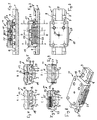
- Fig. 1
- einen Längsschnitt durch eine Montageeinrichtung der Erfindung, wobei das vom Montagesockel zu tragende Zielfernrohr o. dgl. der besseren Deutlichkeit halber weggelassen ist,
- Fig. 2
- eine Seitenansicht der Montageeinrichtung der Fig. 1, gesehen aus der Richtung Z (siehe Fig. 6),
- Fig. 3
- eine Draufsicht auf die Montageeinrichtung der Fig. 1,
- Fig. 4
- den Schnitt A-A in Fig. 2,
- Fig. 5
- den Schnitt B-B in Fig. 2,
- Fig. 6
- den Schnitt C-C in Fig. 2,
- Fig. 7
- den Schnitt D-D in Fig. 2, und
- Fig. 8
- die Montageeinrichtung der Fig. 1, schräg von oben gesehen.
Claims (8)
- Montageeinrichtung zur Anbringung eines Zielfernrohres o. dgl. auf einer an einer Schußwaffe angebrachten oder ausgebildeten Längs-Profilschiene (1), die beiderseits nach außen weisend je eine längsverlaufende Nut oder je einen längsverlaufenden Steg (3, 5) aufweist, in die bzw. den ein abnehmbarer Montagesockel (11) mit einem Steg oder einer Nut (17, 19, 29) längsverschieblich eingreift, der bzw. die jeweils an einer der Seitenkanten des Montagesockels (11) ausgebildet sind, wobeider Montagesockel (11) wenigstens zwei zueinander querverschiebliche Teile (13, 15) aufweist, die durch eine Federanordnung (25) so gegeneinander beweglich belastet sind, daß alleine deren Belastung infolge der Federanordnung (25) deren Eingriff zwischen Längs-Profilschiene (1) und Montagesockel (11) herstellt, unddie Federanordnung (25) eine Federkraft ausübt, die durch Zusammendrücken der beiden Teile (13, 15) mit Daumen und Zeigefinger einer Hand zum Aufheben des Eingriffs überwindbar ist.
- Montageeinrichtung nach Anspruch 1, dadurch gekennzeichnet, daß die Längs-Profilschiene (1) mindestens eine Vertiefung (9) aufweist, in die eine Ausbildung (21) an der zugewandten Seite des Montagesockels (11) bei dessen Aufsetzen eingreift.
- Montageeinrichtung nach einem der vorgenannten Ansprüche 1 oder 2, dadurch gekennzeichnet, daß der Montagesockel (11) die Längs-Profilschiene (1) von deren Außenseiten her umgreift, und daß der eine Teil (15) des Montagesockels (11) innerhalb des anderen Teils (13) geführt und in diesen unter Überwindung der Federkraft eindrückbar ist.
- Montageeinrichtung nach Anspruch 2 oder 3, dadurch gekennzeichnet, daß die Vertiefung als Quernut (9) ausgebildet ist, und daß die Ausbildung des Montagesockels (11), die zum Eingriff in die Quernut (9) der Längs-Profilschiene (1) eingerichtet ist, als Querstift (21) ausgebildet ist, der bevorzugt im nicht-eindrückbaren Teil (13) des Montagesockels (11) befestigt ist.
- Montageeinrichtung nach Anspruch 4, dadurch gekennzeichnet, daß der Querstift (21) neben dem eindrückbaren Teil (15) angeordnet ist.
- Montageeinrichtung nach einem der vorhergehenden Ansprüche, dadurch, daß die Längs-Profilschiene (1) mehrere Quernuten (21) aufweist.
- Montageeinrichtung nach Anspruch 6, dadurch gekennzeichnet, daß sich die Längs-Profilschiene (1) über einen beträchtlichen Teil der Schußwaffe, und bei einem Gewehr als Schußwaffe bevorzugt bis etwa zum vorderen Ende des Vorderschaftes erstreckt.
- Montageeinrichtung nach Anspruch 6 oder 7, dadurch gekennzeichnet, daß die Längs-Profilschiene (1) aus Zink oder aus Kunststoff besteht.
Applications Claiming Priority (3)
| Application Number | Priority Date | Filing Date | Title |
|---|---|---|---|
| DE19918635A DE19918635C1 (de) | 1999-04-23 | 1999-04-23 | Montageeinrichtung |
| DE19918635 | 1999-04-23 | ||
| PCT/EP2000/003601 WO2000065296A1 (de) | 1999-04-23 | 2000-04-20 | Montageeinrichtung zur anbringung eines zielfernrohres an einer schusswaffe |
Publications (2)
| Publication Number | Publication Date |
|---|---|
| EP1088198A1 EP1088198A1 (de) | 2001-04-04 |
| EP1088198B1 true EP1088198B1 (de) | 2002-09-25 |
Family
ID=7905719
Family Applications (1)
| Application Number | Title | Priority Date | Filing Date |
|---|---|---|---|
| EP00920729A Expired - Lifetime EP1088198B1 (de) | 1999-04-23 | 2000-04-20 | Montageeinrichtung zur anbringung eines zielfernrohres an einer schusswaffe |
Country Status (10)
| Country | Link |
|---|---|
| US (1) | US6449893B2 (de) |
| EP (1) | EP1088198B1 (de) |
| KR (1) | KR100445921B1 (de) |
| AT (1) | ATE225026T1 (de) |
| CA (1) | CA2336076C (de) |
| DE (2) | DE19918635C1 (de) |
| DK (1) | DK1088198T3 (de) |
| ES (1) | ES2182798T3 (de) |
| PT (1) | PT1088198E (de) |
| WO (1) | WO2000065296A1 (de) |
Families Citing this family (88)
| Publication number | Priority date | Publication date | Assignee | Title |
|---|---|---|---|---|
| FI110285B (fi) * | 2001-03-05 | 2002-12-31 | Sako Oy | Kiikaritähtäimen pikakiinnitysjalka |
| US6755384B2 (en) * | 2001-04-18 | 2004-06-29 | Hitachi Chemical Co., Ltd. | Flexible platform for liquid handling robots |
| US20030074824A1 (en) * | 2001-10-18 | 2003-04-24 | Sarl Patrick Arachequesne | Mount for a sighting device on a firearm |
| US6705038B2 (en) * | 2001-10-24 | 2004-03-16 | Insight Technology Inc. | Mounting assembly for a weapon accessory |
| US6725594B2 (en) * | 2001-11-04 | 2004-04-27 | Stephen Charles Hines | Rail cover for firearm rail systems |
| USD507619S1 (en) * | 2002-11-04 | 2005-07-19 | First Samco Inc. | Hand guard for a rifle |
| US6874269B2 (en) * | 2003-01-03 | 2005-04-05 | Quarton, Inc. | Connecting device for weapon accessory |
| CA2458412A1 (fr) * | 2003-03-05 | 2004-09-05 | Sarl Patrick Arachequesne | Montage d'un dispositif de visee holographique sur une arme |
| US6931779B1 (en) | 2003-06-05 | 2005-08-23 | Daniel Galuppo, Jr. | Mounting device for attaching an auxiliary sight to a firearm |
| US7222451B2 (en) * | 2004-02-12 | 2007-05-29 | Da Keng | Quick disconnect bipod mount and clamp assembly |
| US7458179B2 (en) * | 2004-03-26 | 2008-12-02 | Swan Richard E | Modular panel system for attaching accessories to a firearm rail system |
| US7325352B2 (en) | 2004-04-06 | 2008-02-05 | Surefire, Llc | Accessory devices for firearms |
| US7117624B2 (en) | 2004-04-06 | 2006-10-10 | Surefire, Llc | Accessory devices for firearms |
| US7591098B2 (en) | 2004-04-06 | 2009-09-22 | Surefire, Llc | Accessory devices for firearms |
| US7332682B2 (en) * | 2004-04-29 | 2008-02-19 | Surefire, Llc | Switches for electrical accessories |
| US7273292B2 (en) * | 2004-04-29 | 2007-09-25 | Surefire, Llc | Switches for firearm electrical accessories |
| USD507620S1 (en) | 2004-05-05 | 2005-07-19 | Richard E. Swan | Pair of interface adapter panels |
| US7481016B2 (en) * | 2004-05-13 | 2009-01-27 | Global Defense Initiatives, Inc. | Optical sight mounting apparatus for firearms |
| US20050268519A1 (en) * | 2004-06-07 | 2005-12-08 | Dov Pikielny | Optical accessory with mounting rail |
| US7552558B1 (en) * | 2004-06-26 | 2009-06-30 | Marlin Daniel Ballard | Mirror sight apparatus with integral rear sight |
| US20070234623A1 (en) * | 2004-12-22 | 2007-10-11 | Carney Sean R | Apparatus for securing a device to a weapon |
| US7334365B2 (en) * | 2005-01-20 | 2008-02-26 | Surefire, Llc | Accessory mount for a firearm |
| US7260912B2 (en) * | 2005-04-29 | 2007-08-28 | Philip Liu | Gun barrel and trigger flashlight and/or laser mount structure |
| US8220445B2 (en) * | 2005-07-20 | 2012-07-17 | Hunter's Maunfacturing Company, Inc. | Crossbow grip guard |
| US7661418B2 (en) | 2005-07-20 | 2010-02-16 | Bednar Richard L | Crossbow grip guard |
| US7444776B2 (en) * | 2005-08-10 | 2008-11-04 | Steve Adams | Vertical lift mount apparatus for firearm accessories |
| US20070068058A1 (en) * | 2005-09-29 | 2007-03-29 | Michael Remo | Night vision monocular housing and universal system for using same in various applications |
| US7305789B2 (en) * | 2006-01-26 | 2007-12-11 | Michael Frost | Reversible weapon telescope mount |
| DE102006024508B4 (de) * | 2006-05-23 | 2014-03-27 | Rheinmetall Soldier Electronics Gmbh | Halterung für Zusatzgeräte an Feuerwaffen |
| US7886476B1 (en) | 2006-07-28 | 2011-02-15 | Swan Richard E | Buffered mounting assembly with magnetic foot |
| US20090282720A1 (en) * | 2006-07-28 | 2009-11-19 | Swan Richard E | Buffered mounting assembly with magnetic foot |
| US7905045B1 (en) | 2006-11-02 | 2011-03-15 | Swan Richard E | Mounting assembly with adjustable spring tension |
| US7757422B1 (en) | 2006-11-02 | 2010-07-20 | Swan Richard E | Mounting assembly with adjustable spring tension |
| US7757423B1 (en) | 2006-11-02 | 2010-07-20 | Swan Richard E | Mounting assembly with adjustable spring tension |
| US8112933B1 (en) | 2006-11-02 | 2012-02-14 | Swan Richard E | Mounting assembly with adjustable spring tension and pivoting lock lever |
| US7493721B2 (en) * | 2006-12-10 | 2009-02-24 | Swan Richard E | Mounting assembly with positive stop for actuator arm |
| US7802395B1 (en) | 2006-12-11 | 2010-09-28 | Swan Richard E | Mounting assembly with positive stop for actuator arm |
| DE102007005142B4 (de) * | 2007-02-01 | 2008-11-20 | Heckler & Koch Gmbh | Anschlussstück |
| DE102007063611A1 (de) | 2007-02-01 | 2008-10-02 | Heckler & Koch Gmbh | Visierelement |
| US7739824B1 (en) | 2007-04-04 | 2010-06-22 | Swan Richard E | Quick detach mount with latching assembly |
| US20090025267A1 (en) * | 2007-07-26 | 2009-01-29 | Alliant Techsystems Inc. | Firearm Rest |
| USD584789S1 (en) | 2007-12-03 | 2009-01-13 | Swan Richard E | Mount |
| USD576327S1 (en) | 2008-01-21 | 2008-09-02 | Eveready Battery Company, Inc. | Lighting device |
| USD619189S1 (en) | 2008-04-18 | 2010-07-06 | Swan Richard E | Buffer pad |
| USD588672S1 (en) | 2008-04-18 | 2009-03-17 | Swan Richard E | Accessory mount |
| USD586875S1 (en) | 2008-04-18 | 2009-02-17 | Swan Richard E | Accessory riser mount |
| USD600311S1 (en) | 2008-06-11 | 2009-09-15 | Swan Richard E | Accessory mount having a buffer pad |
| USD598593S1 (en) | 2008-07-09 | 2009-08-18 | Eveready Battery Co., Inc. | Lighting device |
| USD600108S1 (en) | 2008-11-14 | 2009-09-15 | Swan Richard E | Adjustment nut |
| USD602556S1 (en) | 2008-11-14 | 2009-10-20 | Swan Richard E | Lever arm |
| US20100229450A1 (en) * | 2009-01-12 | 2010-09-16 | Novatac, Inc. | Quick release weapon mount and accessories for use therewith |
| US8156679B1 (en) | 2009-01-14 | 2012-04-17 | Swan Richard E | Accessory module with integrated electronic devices |
| US8156678B2 (en) * | 2009-01-14 | 2012-04-17 | Thomas Trail Hoel | Adaptive rail system |
| US8707606B2 (en) | 2009-01-14 | 2014-04-29 | Thomas Trail Hoel | Rail adaptive platform system |
| DE202009001264U1 (de) | 2009-02-03 | 2009-08-06 | Kilic, Michael Ali | Vorrichtung zur Befestigung einer Zusatzeinrichtung an einer Waffe |
| USD606158S1 (en) | 2009-04-29 | 2009-12-15 | Swan Richard E | Adjustment nut |
| USD604382S1 (en) | 2009-04-29 | 2009-11-17 | Swan Richard E | Quick detach lever assembly |
| USD604383S1 (en) | 2009-04-29 | 2009-11-17 | Swan Richard E | Lever arm |
| US8276307B2 (en) * | 2009-09-30 | 2012-10-02 | Deros Mark A | Mount adapter device utilizing a push system |
| US8499485B2 (en) * | 2009-12-15 | 2013-08-06 | Mark A. Deros | Sliding mount adapter device |
| DE202009017398U1 (de) * | 2009-12-22 | 2010-04-01 | G. Recknagel E.K. Precision Tradition Technology | Klemmsystem für Zusatzgeräte auf einer Picatinny-Schiene |
| USD637260S1 (en) | 2010-01-15 | 2011-05-03 | Swan Richard E | Accessory mount |
| US8322066B2 (en) * | 2010-01-18 | 2012-12-04 | Christopher Westra | Rail attachment mechanism |
| US8490313B2 (en) * | 2011-01-18 | 2013-07-23 | Prototype Productions Incorporated Ventures Two, Llc | Apparatus for mounting accessories on the accessory rail of a weapon |
| US8898949B1 (en) * | 2011-08-04 | 2014-12-02 | Timothy L. Greenwood | Firearm tactical rail mounting bracket |
| US8752325B2 (en) | 2011-08-25 | 2014-06-17 | Leapers, Inc. | Adapter |
| USD683809S1 (en) * | 2012-02-01 | 2013-06-04 | Zackary KasanJian-King | Scope mount for mini-red dot system |
| US8813412B2 (en) | 2012-05-22 | 2014-08-26 | Steven M. Rorick | Quick detachable firearm accessory mount |
| US8857097B2 (en) * | 2012-05-22 | 2014-10-14 | Steven M. Rorick | Quick detachable firearm accessory mount |
| US9068801B1 (en) | 2012-09-11 | 2015-06-30 | Frederick William James Stecher, Jr. | Optics assembly with a base with a platform and removable and interchangeable modules |
| KR101353092B1 (ko) * | 2012-09-28 | 2014-01-20 | 정보선 | 권총용 도트사이트 고정장치 |
| US20140215888A1 (en) * | 2012-10-17 | 2014-08-07 | Eberlestock USA, LLC | Shooting rest including an inclined rail assembly |
| USD709582S1 (en) | 2012-11-12 | 2014-07-22 | WHG Properties, LLC | Firearm handguard |
| US8819980B2 (en) | 2012-11-12 | 2014-09-02 | WHG Properties, LLC | Modular rifle handguard |
| US8973296B1 (en) * | 2014-08-18 | 2015-03-10 | Edward Kocmich, IV | Accessory rail adaptor |
| DE102015108258A1 (de) | 2015-05-26 | 2016-12-01 | Rheinmetall Soldier Electronics Gmbh | Halterung für Zusatzgeräte an Handwaffen |
| US10036613B2 (en) * | 2015-09-09 | 2018-07-31 | Stephen Huff | Systems, devices, and/or methods for managing gun sights |
| US10415932B1 (en) * | 2016-07-22 | 2019-09-17 | Knight Vision LLLP | Adjustable weapon-based mount for a monocular night-vision goggle |
| AT519569B1 (de) * | 2017-04-05 | 2018-08-15 | ISSC Handels GmbH | Schusswaffe mit Adapter für Visiereinrichtung |
| US10578404B2 (en) | 2017-06-05 | 2020-03-03 | Richard E. Swan | Mounting assembly with metal injection molded lever and selective threaded governor post |
| US12038256B2 (en) * | 2019-09-25 | 2024-07-16 | Crimson Trace Corporation | Low profile rail mount for firearm |
| US10969201B1 (en) | 2020-02-13 | 2021-04-06 | Sellmark Corporation | Firearm accessory mount |
| US11473872B2 (en) | 2020-02-13 | 2022-10-18 | Sellmark Corporation | Firearm accessory mount |
| US11460274B2 (en) | 2020-03-02 | 2022-10-04 | David J. Dawson, JR. | Sighting systems, components, and methods |
| US11585620B2 (en) * | 2020-08-09 | 2023-02-21 | Zrodelta, Llc | Mount for a firearm |
| DE102020130869A1 (de) | 2020-11-23 | 2022-05-25 | Michael Ali Kilic | Vorrichtung zur Befestigung einer Zieleinrichtung an einer Faustfeuerwaffe |
| US12281876B2 (en) * | 2021-12-20 | 2025-04-22 | Troy Industries, Inc. | Modular firearm sight mounting system |
| CN217303741U (zh) * | 2022-05-19 | 2022-08-26 | 武汉高明兰光电科技有限公司 | 一种枪用光电仪器的减震装置 |
Family Cites Families (22)
| Publication number | Priority date | Publication date | Assignee | Title |
|---|---|---|---|---|
| DE199957C (de) | 1907-06-29 | 1908-07-02 | Befestigung für Visierfernrohre | |
| DE1008615B (de) | 1953-09-28 | 1957-05-16 | Paul Werner | Befestigungs- und Justiervorrichtung fuer ein Zielfernrohr |
| US3107450A (en) | 1961-05-19 | 1963-10-22 | Olin Mathieson | Glass fiber sight rib for firearm barrels having an outer jacket of glass fibers |
| DE1256113B (de) | 1963-11-13 | 1967-12-07 | Heckler & Koch Gmbh | Traeger fuer ein optisches Zielgeraet |
| US3612462A (en) * | 1969-08-26 | 1971-10-12 | Quick Set Inc | Instrument mount assembly |
| US3835565A (en) | 1973-02-20 | 1974-09-17 | Clear View Mfg Co | Telescopic sight mounting |
| US3877166A (en) * | 1974-01-14 | 1975-04-15 | William A Ward | Gunsight mount with spring biased jaw |
| US3986285A (en) | 1975-05-16 | 1976-10-19 | Krisay Robert J | Detachable top side mount |
| US4383371A (en) * | 1982-01-29 | 1983-05-17 | Coffey Fred W | Scope mount for handgun |
| DE3429925A1 (de) * | 1984-08-14 | 1986-02-27 | Kürbi & Niggeloh, 5608 Radevormwald | Stativkopf mit abnehmbarer kamera-auflageplatte |
| DE8510245U1 (de) | 1985-04-06 | 1985-07-18 | Ernst Apel, Feinmechanische Erzeugnisse, 8708 Gerbrunn | Zielfernrohrhalterung |
| SE455439B (sv) * | 1987-03-09 | 1988-07-11 | Swedemount Ab | Snabbfeste for ett kikarsikte |
| USD308089S (en) * | 1987-12-04 | 1990-05-22 | Sanders Ronald J | Sight aiming instrument for weaponry |
| US4905396A (en) * | 1989-01-11 | 1990-03-06 | Bechtel Daniel L | Method and apparatus for mounting an auxiliary sighting aid on a firearm |
| EP0444300A3 (en) * | 1990-02-24 | 1992-08-12 | Otto Repa | Telescopic sight mounting |
| DE9006133U1 (de) * | 1990-05-30 | 1990-08-23 | Fa. Carl Zeiss, 7920 Heidenheim | Gesteck zur lösbaren Befestigung eines Zielfernrohres auf einem Gewehr |
| DE4133932C2 (de) * | 1991-10-14 | 1999-12-02 | Georg Recknagel | Haltevorrichtung für Zieleinrichtungen auf Jagd- und Sportwaffen |
| DE4444677C1 (de) | 1994-12-15 | 1996-02-08 | Apel Ernst Gmbh | Lösbare Zielfernrohrhalterung |
| US5680725A (en) * | 1997-01-02 | 1997-10-28 | Burris Company, Inc. | Positive-aligning quick mount |
| US6026580A (en) * | 1997-01-24 | 2000-02-22 | Larue; Mark C. | Aiming sight mount |
| US5926964A (en) * | 1997-12-22 | 1999-07-27 | Korapaty; Bob | Reliable scope mount |
| US6295754B1 (en) * | 1998-10-21 | 2001-10-02 | Rodney H. Otteman | Aiming Device with adjustable height mount and auxiliary equipment mounting features |
-
1999
- 1999-04-23 DE DE19918635A patent/DE19918635C1/de not_active Expired - Fee Related
-
2000
- 2000-04-20 KR KR10-2000-7014575A patent/KR100445921B1/ko not_active Expired - Fee Related
- 2000-04-20 EP EP00920729A patent/EP1088198B1/de not_active Expired - Lifetime
- 2000-04-20 PT PT00920729T patent/PT1088198E/pt unknown
- 2000-04-20 AT AT00920729T patent/ATE225026T1/de not_active IP Right Cessation
- 2000-04-20 ES ES00920729T patent/ES2182798T3/es not_active Expired - Lifetime
- 2000-04-20 DE DE50000549T patent/DE50000549D1/de not_active Expired - Fee Related
- 2000-04-20 DK DK00920729T patent/DK1088198T3/da active
- 2000-04-20 WO PCT/EP2000/003601 patent/WO2000065296A1/de not_active Ceased
- 2000-04-20 CA CA002336076A patent/CA2336076C/en not_active Expired - Fee Related
- 2000-12-22 US US09/747,587 patent/US6449893B2/en not_active Expired - Fee Related
Also Published As
| Publication number | Publication date |
|---|---|
| US6449893B2 (en) | 2002-09-17 |
| EP1088198A1 (de) | 2001-04-04 |
| WO2000065296A1 (de) | 2000-11-02 |
| DE50000549D1 (de) | 2002-10-31 |
| DK1088198T3 (da) | 2003-01-06 |
| CA2336076A1 (en) | 2000-11-02 |
| PT1088198E (pt) | 2003-01-31 |
| US20010022044A1 (en) | 2001-09-20 |
| KR20010072634A (ko) | 2001-07-31 |
| ES2182798T3 (es) | 2003-03-16 |
| KR100445921B1 (ko) | 2004-08-25 |
| ATE225026T1 (de) | 2002-10-15 |
| CA2336076C (en) | 2004-06-22 |
| DE19918635C1 (de) | 2000-07-20 |
Similar Documents
| Publication | Publication Date | Title |
|---|---|---|
| EP1088198B1 (de) | Montageeinrichtung zur anbringung eines zielfernrohres an einer schusswaffe | |
| DE102011013575B4 (de) | Vorrichtung zum Befestigen eines Zusatzgerätes an einer Schusswaffe | |
| EP1716384A1 (de) | Waffe mit montageschiene | |
| EP4001825B1 (de) | Vorrichtung zur befestigung einer zieleinrichtung an einer faustfeuerwaffe | |
| EP0444300A2 (de) | Zielfernrohrmontage | |
| EP2956732B1 (de) | Universelle zielfernrohrmontage für handfeuerwaffen | |
| DE10036728B4 (de) | Waffensystem | |
| DE102012012917A1 (de) | Aufkippmontage mit zusätzlichem Anschlag | |
| DE2023270A1 (de) | Handfeuerwaffe mit Tragegriff | |
| EP1478897A1 (de) | Halterung zur anbringung eines geräts, wie ein zielfernrohr, an einer waffe | |
| EP2615408B1 (de) | Montagevorrichtung für ein Zielfernrohr bei einer Jagd- oder Sportwaffe | |
| DE102010010673B4 (de) | Schnellwechselmontagesystem | |
| EP2570762B1 (de) | Jagd- und Sportwaffe mit Halterung für ein Zielfernrohr | |
| DE19538006C1 (de) | Justiereinrichtung für eine zumindest zweiläufige Waffe | |
| DE102006024508B4 (de) | Halterung für Zusatzgeräte an Feuerwaffen | |
| DE102007005142A1 (de) | Anschlussstück | |
| DE102006001658B4 (de) | Adapter für ein Gewehr | |
| DE102009011743A1 (de) | Aufschubmontage | |
| EP1703246B1 (de) | Mehrläufige Handfeuerwaffe | |
| AT18345U1 (de) | Pistole mit Kimme und Korn und Kimme und Korn für eine solche | |
| DE202024100979U1 (de) | Vorrichtung zur Befestigung einer Zieleinrichtung an einer Schusswaffe | |
| DE20012672U1 (de) | Visierung mit variabler Erhöhung und seitlicher Verschiebung der Visierlinien | |
| DE9316132U1 (de) | Montage zur Befestigung von Zielfernrohren an Handfeuerwaffen | |
| DE29803164U1 (de) | Gewehrstütze | |
| DE1453885A1 (de) | Vorrichtung zur Anbringung von Zielgeraeten |
Legal Events
| Date | Code | Title | Description |
|---|---|---|---|
| PUAI | Public reference made under article 153(3) epc to a published international application that has entered the european phase |
Free format text: ORIGINAL CODE: 0009012 |
|
| 17P | Request for examination filed |
Effective date: 20001130 |
|
| AK | Designated contracting states |
Kind code of ref document: A1 Designated state(s): AT BE CH CY DE DK ES FI FR GB GR IE IT LI LU MC NL PT SE |
|
| GRAG | Despatch of communication of intention to grant |
Free format text: ORIGINAL CODE: EPIDOS AGRA |
|
| GRAG | Despatch of communication of intention to grant |
Free format text: ORIGINAL CODE: EPIDOS AGRA |
|
| GRAH | Despatch of communication of intention to grant a patent |
Free format text: ORIGINAL CODE: EPIDOS IGRA |
|
| 17Q | First examination report despatched |
Effective date: 20020301 |
|
| GRAH | Despatch of communication of intention to grant a patent |
Free format text: ORIGINAL CODE: EPIDOS IGRA |
|
| GRAA | (expected) grant |
Free format text: ORIGINAL CODE: 0009210 |
|
| AK | Designated contracting states |
Kind code of ref document: B1 Designated state(s): AT BE CH CY DE DK ES FI FR GB GR IE IT LI LU MC NL PT SE |
|
| PG25 | Lapsed in a contracting state [announced via postgrant information from national office to epo] |
Ref country code: GR Free format text: LAPSE BECAUSE OF FAILURE TO SUBMIT A TRANSLATION OF THE DESCRIPTION OR TO PAY THE FEE WITHIN THE PRESCRIBED TIME-LIMIT Effective date: 20020925 Ref country code: FI Free format text: LAPSE BECAUSE OF FAILURE TO SUBMIT A TRANSLATION OF THE DESCRIPTION OR TO PAY THE FEE WITHIN THE PRESCRIBED TIME-LIMIT Effective date: 20020925 Ref country code: IE Free format text: LAPSE BECAUSE OF FAILURE TO SUBMIT A TRANSLATION OF THE DESCRIPTION OR TO PAY THE FEE WITHIN THE PRESCRIBED TIME-LIMIT Effective date: 20020925 |
|
| REF | Corresponds to: |
Ref document number: 225026 Country of ref document: AT Date of ref document: 20021015 Kind code of ref document: T |
|
| REG | Reference to a national code |
Ref country code: GB Ref legal event code: FG4D Free format text: NOT ENGLISH |
|
| REG | Reference to a national code |
Ref country code: CH Ref legal event code: EP |
|
| REG | Reference to a national code |
Ref country code: CH Ref legal event code: NV Representative=s name: E. BLUM & CO. PATENTANWAELTE |
|
| REG | Reference to a national code |
Ref country code: IE Ref legal event code: FG4D Free format text: GERMAN |
|
| REF | Corresponds to: |
Ref document number: 50000549 Country of ref document: DE Date of ref document: 20021031 |
|
| GBT | Gb: translation of ep patent filed (gb section 77(6)(a)/1977) |
Effective date: 20021205 |
|
| REG | Reference to a national code |
Ref country code: DK Ref legal event code: T3 |
|
| REG | Reference to a national code |
Ref country code: PT Ref legal event code: SC4A Free format text: AVAILABILITY OF NATIONAL TRANSLATION Effective date: 20021125 |
|
| ET | Fr: translation filed | ||
| REG | Reference to a national code |
Ref country code: ES Ref legal event code: FG2A Ref document number: 2182798 Country of ref document: ES Kind code of ref document: T3 |
|
| PG25 | Lapsed in a contracting state [announced via postgrant information from national office to epo] |
Ref country code: LU Free format text: LAPSE BECAUSE OF NON-PAYMENT OF DUE FEES Effective date: 20030420 Ref country code: CY Free format text: LAPSE BECAUSE OF FAILURE TO SUBMIT A TRANSLATION OF THE DESCRIPTION OR TO PAY THE FEE WITHIN THE PRESCRIBED TIME-LIMIT Effective date: 20030420 |
|
| PG25 | Lapsed in a contracting state [announced via postgrant information from national office to epo] |
Ref country code: MC Free format text: LAPSE BECAUSE OF NON-PAYMENT OF DUE FEES Effective date: 20030430 |
|
| REG | Reference to a national code |
Ref country code: IE Ref legal event code: FD4D Ref document number: 1088198E Country of ref document: IE |
|
| PLBE | No opposition filed within time limit |
Free format text: ORIGINAL CODE: 0009261 |
|
| STAA | Information on the status of an ep patent application or granted ep patent |
Free format text: STATUS: NO OPPOSITION FILED WITHIN TIME LIMIT |
|
| 26N | No opposition filed |
Effective date: 20030626 |
|
| PGFP | Annual fee paid to national office [announced via postgrant information from national office to epo] |
Ref country code: PT Payment date: 20070416 Year of fee payment: 8 |
|
| PGFP | Annual fee paid to national office [announced via postgrant information from national office to epo] |
Ref country code: NL Payment date: 20070417 Year of fee payment: 8 |
|
| PGFP | Annual fee paid to national office [announced via postgrant information from national office to epo] |
Ref country code: AT Payment date: 20070423 Year of fee payment: 8 |
|
| PGFP | Annual fee paid to national office [announced via postgrant information from national office to epo] |
Ref country code: CH Payment date: 20070424 Year of fee payment: 8 Ref country code: SE Payment date: 20070424 Year of fee payment: 8 |
|
| PGFP | Annual fee paid to national office [announced via postgrant information from national office to epo] |
Ref country code: DK Payment date: 20070425 Year of fee payment: 8 Ref country code: ES Payment date: 20070425 Year of fee payment: 8 |
|
| PGFP | Annual fee paid to national office [announced via postgrant information from national office to epo] |
Ref country code: DE Payment date: 20070430 Year of fee payment: 8 |
|
| REG | Reference to a national code |
Ref country code: CH Ref legal event code: PFA Owner name: HECKLER & KOCH GMBH Free format text: HECKLER & KOCH GMBH#ALTE STEIGE 7#78727 OBERNDORF/NECKAR (DE) -TRANSFER TO- HECKLER & KOCH GMBH#ALTE STEIGE 7#78727 OBERNDORF/NECKAR (DE) |
|
| PGFP | Annual fee paid to national office [announced via postgrant information from national office to epo] |
Ref country code: GB Payment date: 20070425 Year of fee payment: 8 |
|
| PGFP | Annual fee paid to national office [announced via postgrant information from national office to epo] |
Ref country code: BE Payment date: 20070419 Year of fee payment: 8 |
|
| PGFP | Annual fee paid to national office [announced via postgrant information from national office to epo] |
Ref country code: FR Payment date: 20070418 Year of fee payment: 8 |
|
| BERE | Be: lapsed |
Owner name: *HECKLER & KOCH G.M.B.H. Effective date: 20080430 |
|
| REG | Reference to a national code |
Ref country code: PT Ref legal event code: MM4A Free format text: LAPSE DUE TO NON-PAYMENT OF FEES Effective date: 20081020 |
|
| REG | Reference to a national code |
Ref country code: CH Ref legal event code: PL |
|
| REG | Reference to a national code |
Ref country code: DK Ref legal event code: EBP |
|
| EUG | Se: european patent has lapsed | ||
| GBPC | Gb: european patent ceased through non-payment of renewal fee |
Effective date: 20080420 |
|
| NLV4 | Nl: lapsed or anulled due to non-payment of the annual fee |
Effective date: 20081101 |
|
| PG25 | Lapsed in a contracting state [announced via postgrant information from national office to epo] |
Ref country code: NL Free format text: LAPSE BECAUSE OF NON-PAYMENT OF DUE FEES Effective date: 20081101 Ref country code: CH Free format text: LAPSE BECAUSE OF NON-PAYMENT OF DUE FEES Effective date: 20080430 Ref country code: LI Free format text: LAPSE BECAUSE OF NON-PAYMENT OF DUE FEES Effective date: 20080430 Ref country code: PT Free format text: LAPSE BECAUSE OF NON-PAYMENT OF DUE FEES Effective date: 20081020 Ref country code: DE Free format text: LAPSE BECAUSE OF NON-PAYMENT OF DUE FEES Effective date: 20081101 |
|
| REG | Reference to a national code |
Ref country code: FR Ref legal event code: ST Effective date: 20081231 |
|
| PG25 | Lapsed in a contracting state [announced via postgrant information from national office to epo] |
Ref country code: AT Free format text: LAPSE BECAUSE OF NON-PAYMENT OF DUE FEES Effective date: 20080420 |
|
| PG25 | Lapsed in a contracting state [announced via postgrant information from national office to epo] |
Ref country code: BE Free format text: LAPSE BECAUSE OF NON-PAYMENT OF DUE FEES Effective date: 20080430 |
|
| PG25 | Lapsed in a contracting state [announced via postgrant information from national office to epo] |
Ref country code: FR Free format text: LAPSE BECAUSE OF NON-PAYMENT OF DUE FEES Effective date: 20080430 Ref country code: DK Free format text: LAPSE BECAUSE OF NON-PAYMENT OF DUE FEES Effective date: 20080430 |
|
| REG | Reference to a national code |
Ref country code: ES Ref legal event code: FD2A Effective date: 20080421 |
|
| PG25 | Lapsed in a contracting state [announced via postgrant information from national office to epo] |
Ref country code: GB Free format text: LAPSE BECAUSE OF NON-PAYMENT OF DUE FEES Effective date: 20080420 |
|
| PG25 | Lapsed in a contracting state [announced via postgrant information from national office to epo] |
Ref country code: ES Free format text: LAPSE BECAUSE OF NON-PAYMENT OF DUE FEES Effective date: 20080421 |
|
| PGFP | Annual fee paid to national office [announced via postgrant information from national office to epo] |
Ref country code: IT Payment date: 20070609 Year of fee payment: 8 |
|
| PGRI | Patent reinstated in contracting state [announced from national office to epo] |
Ref country code: IT Effective date: 20090601 |
|
| PG25 | Lapsed in a contracting state [announced via postgrant information from national office to epo] |
Ref country code: SE Free format text: LAPSE BECAUSE OF NON-PAYMENT OF DUE FEES Effective date: 20080421 |
|
| PGRI | Patent reinstated in contracting state [announced from national office to epo] |
Ref country code: IT Effective date: 20090601 |