EP1088198B1 - Mounting device for fitting a telescopic sight to a fire arm - Google Patents
Mounting device for fitting a telescopic sight to a fire arm Download PDFInfo
- Publication number
- EP1088198B1 EP1088198B1 EP00920729A EP00920729A EP1088198B1 EP 1088198 B1 EP1088198 B1 EP 1088198B1 EP 00920729 A EP00920729 A EP 00920729A EP 00920729 A EP00920729 A EP 00920729A EP 1088198 B1 EP1088198 B1 EP 1088198B1
- Authority
- EP
- European Patent Office
- Prior art keywords
- mounting base
- rail
- mounting
- longitudinal sectional
- mounting device
- Prior art date
- Legal status (The legal status is an assumption and is not a legal conclusion. Google has not performed a legal analysis and makes no representation as to the accuracy of the status listed.)
- Expired - Lifetime
Links
- 210000003811 finger Anatomy 0.000 claims description 7
- HCHKCACWOHOZIP-UHFFFAOYSA-N Zinc Chemical compound [Zn] HCHKCACWOHOZIP-UHFFFAOYSA-N 0.000 claims description 6
- 229910052725 zinc Inorganic materials 0.000 claims description 6
- 239000011701 zinc Substances 0.000 claims description 6
- 238000003825 pressing Methods 0.000 claims description 3
- 210000003813 thumb Anatomy 0.000 claims description 2
- 230000007246 mechanism Effects 0.000 abstract description 5
- 210000000078 claw Anatomy 0.000 description 7
- 230000006835 compression Effects 0.000 description 5
- 238000007906 compression Methods 0.000 description 5
- 239000000463 material Substances 0.000 description 5
- 230000008901 benefit Effects 0.000 description 3
- 238000009434 installation Methods 0.000 description 3
- 238000004519 manufacturing process Methods 0.000 description 3
- 229910000831 Steel Inorganic materials 0.000 description 2
- 230000000295 complement effect Effects 0.000 description 2
- 230000000694 effects Effects 0.000 description 2
- 210000000245 forearm Anatomy 0.000 description 2
- 230000003287 optical effect Effects 0.000 description 2
- 239000010959 steel Substances 0.000 description 2
- 229910000838 Al alloy Inorganic materials 0.000 description 1
- 238000005299 abrasion Methods 0.000 description 1
- 238000005266 casting Methods 0.000 description 1
- 238000011109 contamination Methods 0.000 description 1
- 239000013078 crystal Substances 0.000 description 1
- 230000000994 depressogenic effect Effects 0.000 description 1
- 238000004512 die casting Methods 0.000 description 1
- 238000006073 displacement reaction Methods 0.000 description 1
- 238000005516 engineering process Methods 0.000 description 1
- 239000003365 glass fiber Substances 0.000 description 1
- 238000001746 injection moulding Methods 0.000 description 1
- 210000000629 knee joint Anatomy 0.000 description 1
- 229910001234 light alloy Inorganic materials 0.000 description 1
- 238000003754 machining Methods 0.000 description 1
- 238000002844 melting Methods 0.000 description 1
- 230000008018 melting Effects 0.000 description 1
- 229910052751 metal Inorganic materials 0.000 description 1
- 239000002184 metal Substances 0.000 description 1
- 238000000034 method Methods 0.000 description 1
- 230000008569 process Effects 0.000 description 1
- 230000002787 reinforcement Effects 0.000 description 1
- 230000008439 repair process Effects 0.000 description 1
- 239000007787 solid Substances 0.000 description 1
- 238000001931 thermography Methods 0.000 description 1
- 230000007704 transition Effects 0.000 description 1
Images
Classifications
-
- F—MECHANICAL ENGINEERING; LIGHTING; HEATING; WEAPONS; BLASTING
- F41—WEAPONS
- F41G—WEAPON SIGHTS; AIMING
- F41G1/00—Sighting devices
- F41G1/38—Telescopic sights specially adapted for smallarms or ordnance; Supports or mountings therefor
- F41G1/387—Mounting telescopic sights on smallarms
-
- F—MECHANICAL ENGINEERING; LIGHTING; HEATING; WEAPONS; BLASTING
- F41—WEAPONS
- F41G—WEAPON SIGHTS; AIMING
- F41G11/00—Details of sighting or aiming apparatus; Accessories
- F41G11/001—Means for mounting tubular or beam shaped sighting or aiming devices on firearms
- F41G11/003—Mountings with a dove tail element, e.g. "Picatinny rail systems"
-
- F—MECHANICAL ENGINEERING; LIGHTING; HEATING; WEAPONS; BLASTING
- F41—WEAPONS
- F41G—WEAPON SIGHTS; AIMING
- F41G11/00—Details of sighting or aiming apparatus; Accessories
- F41G11/001—Means for mounting tubular or beam shaped sighting or aiming devices on firearms
Definitions
- the invention relates to a mounting device for attachment a telescopic sight or the like on one on one Firearm attached or trained longitudinal profile rail, the one on each side pointing outwards longitudinal groove or a longitudinal web each has a removable mounting base engages longitudinally displaceably with a web or a groove, the or each on one of the side edges of the mounting base are formed, as in claim 1 outlined.
- the invention is such an assembly device.
- the longitudinal profile rail can be on the top of the gun be attached so that their surface with normal stop with a horizontal direction of fire. But it can also be attached to the side of the weapon be so that their surface is normal stop runs approximately vertically; or elsewhere and coupled to the weapon, such as on a machine gun mount.
- the length of the longitudinal mounting rail can only be a few centimeters. But it can also be significant be longer.
- a clamping device in the simplest case a clamping screw, penetrates across the mounting base and serves to to clamp this on the dovetail.
- the The shaft of the clamping screw is between the mounting base and the longitudinal mounting rail arranged that the Position of the telescopic sight in the longitudinal direction of the weapon always is reliably reproducible.
- Such an assembly facility can be seen, for example, in US-A-3 887 166 (Ward).
- This known assembly device is advantageous because it has a small size. Your disadvantage lies however in the cumbersome postponing and finding out the correct mounting position, as well as in the necessarily quite high manufacturing accuracy.
- the short end of the swivel lever is with the other part of the Assembly base connected via a knee joint mechanism, which allows this other part with great External force against the longitudinal mounting rail, i.e. in Towards the first part. Because the toggle mechanism is kinked in its rest position he a force in the direction of a backward movement of the movable Part. It is therefore a powerful disc spring package provided that this backward movement compensated and at the same time the swivel lever in the holds the buckled position of the toggle mechanism.
- the latter assembly device is advantageous because it can be put on and taken off quickly, and because the disc spring package manufacturing inaccuracies can compensate.
- their disadvantage lies in the bulky version because of the long swivel lever is required.
- the invention is based on this prior art based on the task, the known assembly facilities to improve in that their benefits are effective remain, but their disadvantages are eliminated as far as possible.
- the invention connects through the mounting base with the longitudinal profile rail Engaging element that only with a limited and by external forces completely releasable spring force engaged is held.
- the relative displacement in the transverse direction is quite possible.
- night aiming device o. Damage occur that requires at least one repair and immediate reuse impossible make: about when a rifle with night aiming device falls two meters on the pavement. Then the night target device then shows no picture more. It therefore does not need to be attached to the rifle to stay. Rather, it is possible that the inertia of the falling night target device the spring arrangement according to the invention consuming energy so loaded that it releases the night target device braked. It is therefore quite conceivable that the inventions. proper installation when the rifle falls mounted accessory this just by being released protected from the weapon from damage by a conventional Assembly would have been inevitable.
- Another advantage is that according to the invention all long Clamping lever and also the great machining accuracy inaccuracies are eliminated since the spring arrangement is able to compensate easily. At most there is one Set screw required to the clamping force of the spring assembly adjust.
- the assembly device according to the invention is preferred the positive connection between the longitudinal profile rail and the mounting base to prevent it from slipping to prevent due to external forces (claim 2).
- the mounting base with such a clamping force clamped on the longitudinal profile rail that this cannot be overcome without damaging the parts.
- US-A-3 877 166 (Ward) Connection shown by a cross bolt, but this only serves to position the assembly base, not its hold against slipping in the longitudinal direction the weapon. This slipping is in the state of the Technology sufficiently prevented by the clamping, so that the present, additional, form-fitting Hold intervention is not required.
- the form-fitting in a transverse groove Longitudinal rail engages because of the clamping effect the spring force is not always sufficient to the mounting base with the rifle he carried To prevent slipping.
- the spring force of the Assembly device according to the invention is usually sufficient around a rifle scope or the like with normal handling to hold the gun firmly on it.
- both sides in the longitudinal mounting rail form a protruding edge in which the engage both parts of the mounting base from the inside, by being pushed apart by the spring force. Extensions of these parts by the fingers of the Users can be taken to need to lose weight of the mounting base only to be compressed. At least a bevel on the two parts can do this ensure that the mounting base is only on the longitudinal profile rail needs to be pushed open.
- the in the Bevels engaging edges of the longitudinal profile rails press the two parts of the mounting base under Overcoming the spring force together. In such a trough-shaped trained longitudinal profile rail can but collect dirt easily, especially when on the Top of the gun is attached horizontally.
- the two side edges of the longitudinal profile rail are therefore preferred encircled from the outside, because then an insufficient Seat due to the contamination of the longitudinal profile rail is rather excluded.
- the spring force causes then that the two parts of the mounting base on top of each other to be charged.
- the part that is equipped with the handle is referred to as an indentable part while the other part is called the non-indentable part becomes.
- the guidance of the pushable part in the non-pushable Part ensures that the two parts assembled mounting base is sufficiently longitudinally stable.
- a particularly simple training on the mounting base is a cross pin, preferably a round cross pin, which at the mounting base is parallel to a transverse groove extends and engages in these. It is possible arrange the cross pin in the push-in part. It is but more appropriate, the cross pin in the non-depressible Arrange part of the mounting base, since then there is no danger there is movement of the depressible part hindered by the abrasion of the cross pin on the transverse groove will (claim 3).
- the cross pin is preferably next to the push-in Partly arranged, i.e. in the longitudinal direction of the longitudinal profile rail seen, in front of or behind the impressible Part so that the cross pin is not the pushable part enforce needs (claim 4).
- the mounting base with the cross pin in each most suitable transverse groove are used. It It is possible to use a riflescope in the best possible way Arrange eye relief when the shooter has a thick shatterproof vest and winter clothing. It can also any other facilities for one and the same rifle is intended, such as a night target, a red dot sight, a sight for special ammunition, about a grenade launcher visor or the like. These can, depending according to length and weight, one or more mounting bases have and with the cross pin of or each mounting base each inserted in a suitable transverse groove become.
- the longitudinal profile rail is particularly advantageous to extend forward, approximately to the end of the fore-end or even to the mouth.
- An optical or illuminated one Grain (marked with "eagle's eye” for marksmen) can be put on as well as a combination from optical riflescope and image intensifier or Image converter to make a high performance night target device at night or a thermal imaging night target to have.
- These often long devices can then be used two or even with several mounting bases become. It is put on by means of a bevel relieved at the lower edge of the push-in part, that of the engaging edge of the longitudinal profile rail is facing.
- the target device then only needs this Splint to be pushed open. However, losing weight a hand is required for each base, which is the push-in Part. But it is also possible that part of a catch device or locking device that can be pushed in assign to keep it depressed. In this case the mentioned bevel is not necessary.
- a plastic rail would be special for a rifle then an advantage if the longitudinal profile rail is at least about the length of the fore-end would have to extend at the front, for example around an equipment rack for to form a universal use.
- a plastic rail could be even easier than one Be light alloy rail.
- the Dimensions are of course not too small and are in generally be larger than with previous assembly facilities.
- the width of a longitudinal profile rail Plastic measured transversely to the longitudinal direction of the rifle, So the distance between the two engagement edges has a measure proven from 20 to 25 mm.
- the engagement length of the mounting base is about the same measure.
- the material of the mounting base is preferably light metal, such as an aluminum alloy, since the support of the spring device can give higher surface pressures than they permissible for plastic or zinc.
- top assuming the normal position of a rifle, where the shot direction is horizontal.
- Front points in the direction of the shot.
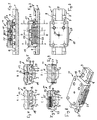
- the mounting device comprises a longitudinal profile rail 1 made of plastic, which is preferably made by injection molding, about a reinforcement made of glass fibers or the like. sprayed and has: a solid lower part 2, the has an approximately flat rectangular cross section and on the Top of a rifle is mountable; an additional two Upper parts 4 on the two sides of the lower part 2 sit and each have a square cross-section, that in the form of an isosceles triangle is extended on the outside, in such a way that the free tips these cross-sectional triangles each have longitudinal engagement edges 3, 5 form, each over the lower part 2 survive to the outside. Between the two tops 4 an upwardly open longitudinal groove 7 is recessed.
- transverse grooves 9 which are extend through the upper parts 4 of the rail profile and do not reach all the way down to the bottom of the longitudinal groove 7.
- the cross section of these transverse grooves 9 has the shape of a squat, lying rectangle.
- the rail 1 extends from one point above the front end of the piston neck up to one point the front end of the forearm of a rifle and is only attached in two places. On one of these The rail 1 is set in all three coordinate directions fixed on the other only in two coordinate directions, similar to a road bridge with a fixed one and a loose support to relative thermal expansion to be able to carry on to the rifle without warping.
- a mounting base 11 On the rail 1 is a mounting base 11, which consists of a pushable part 15 and a non-pushable Part 13 is formed.
- the non-crushable part 13 has a claw 17, 19 on each side, which are complementary to the engaging edge 5 of the rail 1 and encompasses this edge 5.
- the a 17 of the claws 17, 19 in the longitudinal direction (direction of Extension of the rail 1) is shorter than the other Claw 19.
- the area of claw 19 penetrates Embossed cross pin 21, which is attached to the mounting base 11 in a transverse groove 9 with little or no Game intervenes.
- the depressible part 15 is movable in the transverse direction guided part 13. It sticks out of one Long side of the non-crushable part 13 out - here on the side of the engaging edge 5 - and there has one Handle 23 on the side of the mounting base 11 protrudes and can be pressed inside by hand.
- a limit pin 27 which is hammered into the non-depressible part 13, engages in the push-in part 15 in its end position and limits its movement.
- the push-in part 15 becomes one Pressed the rest position, in which the handle 23 from the non-depressible Part 13 protrudes sideways.
- On the opposite Side is on the push-in part 15 downward, lateral longitudinal web formed, in the side facing the rail 1, an engagement groove 29 is formed, which is complementary to the engaging edge 3 is formed and encompasses them.
- the engagement groove 29 can be seen with the force of the compression springs 25 against the Engagement edge 3 pressed so that the mounting base 11th then held essentially immovable on the rail 1 becomes.
- the mounting base 11 is clamped on the rail 1 only with the spring force of the compression springs 25. So far the frictional force resulting from the clamping is not sufficient to hold the mounting base 11 in the longitudinal direction, the cross pin 21 provides this hold, which in a the transverse grooves 9 engages.
- the length of the two claws 17, 19 is approximately equal to that Length of the engagement groove 29. From the shorter of these lengths, the spring force of the compression springs 25 and the geometry the engaging edges 3, 5 and the claws 17, 19 results the maximum surface pressure on the rail 1. This is dimensioned so that the plastic of the rail 1 through the engagement of the claws 17, 19 and the engagement groove 29 undergoes no permanent deformation.
Landscapes
- Engineering & Computer Science (AREA)
- General Engineering & Computer Science (AREA)
- Physics & Mathematics (AREA)
- Optics & Photonics (AREA)
- Aiming, Guidance, Guns With A Light Source, Armor, Camouflage, And Targets (AREA)
- Telescopes (AREA)
- Clamps And Clips (AREA)
- Connection Of Plates (AREA)
- Joining Of Building Structures In Genera (AREA)
- Mutual Connection Of Rods And Tubes (AREA)
- Prostheses (AREA)
Abstract
Description
Die Erfindung betrifft eine Montageeinrichtung zur Anbringung eines Zielfernrohres o. dgl. auf einer an einer Schußwaffe angebrachten oder ausgebildeten Längs-Profilschiene, die beiderseits nach außen weisend je eine längsverlaufende Nut oder je einen längsverlaufenden Steg aufweist, in die bzw. den ein abnehmbarer Montagesockel mit einem Steg oder einer Nut längsverschieblich eingreift, der bzw. die jeweils an einer der Seitenkanten des Montagesockels ausgebildet sind, wie im Anspruch 1 umrissen.The invention relates to a mounting device for attachment a telescopic sight or the like on one on one Firearm attached or trained longitudinal profile rail, the one on each side pointing outwards longitudinal groove or a longitudinal web each has a removable mounting base engages longitudinally displaceably with a web or a groove, the or each on one of the side edges of the mounting base are formed, as in claim 1 outlined.
Zum Stand der Technik werden die US 3 877 166 und EP
0 444 300 A2 benannt.US 3 877 166 and EP become
Zur justierten Halterung von Zielfernrohren o. dgl. auf Waffen gibt es recht unterschiedliche Arten von Montageeinrichtungen. Allen ist das grundlegende Bestreben gemeinsam, das montierte Zielfernrohr so unverrückbar wie nur irgend möglich auf der Waffe zu befestigen, damit es seine Relativlage zur Waffe niemals ändert.For the adjusted mounting of riflescopes or the like Weapons have quite different types of assembly facilities. Common to all is the fundamental endeavor the mounted riflescope as immovable as only possible to attach to the weapon so it never changes its position relative to the weapon.
Bei aufwendigen Jagdwaffen werden meist handwerklich gearbeitete Montageeinrichtungen verwendet, die aufs genaueste hergestellte, komplizierte Flächen aufweisen. Bei Sportwaffen und Militärgewehren hingegen zieht man meist einfachere und robustere Montageeinrichtungen vor, die auf die Grundform der sog. Aufschubmontage zurückgehen. Bei der Erfindung handelt es sich um eine solche Montageeinrichtung.In the case of elaborate hunting weapons, mostly handcrafted ones are used Assembly facilities used, the most accurate have manufactured, complicated surfaces. at Sporting weapons and military rifles, on the other hand, are usually drawn simpler and more robust assembly facilities that go back to the basic form of so-called slide-on installation. The invention is such an assembly device.
Bei einer solchen Aufschubmontage ist an der Waffe eine schwalbenschwanzartige Längs-Profilschiene angebracht oder ausgebildet; und am Zielfernrohr oder dergleichen ein abnehmbarer Fuß oder Montagesockel mit einem Mutterprofil, das auf die Längs-Profilschiene der Waffe mit geringem Spiel aufschiebbar ist.With such a slide-on installation, there is one on the weapon dovetail-like longitudinal profile rail attached or trained; and on the scope or the like a removable foot or mounting base with a nut profile, that on the longitudinal rail of the weapon with little Game is postponed.
Die Längs-Profilschiene kann auf der Oberseite der Waffe angebracht sein, so daß ihre Oberfläche bei normalem Anschlag mit horizontaler Schußrichtung horizontal verläuft. Sie kann aber auch seitlich an der Waffe angebracht sein, so daß ihre Oberfläche bei normalem Anschlag etwa vertikal verläuft; oder an einer sonstigen Stelle und an die Waffe angekoppelt, wie etwa auf einer MG-Fahrzeuglafette. Die Länge der Längs-Profilschiene kann nur wenige Zentimeter betragen. Sie kann aber auch bedeutend länger sein.The longitudinal profile rail can be on the top of the gun be attached so that their surface with normal stop with a horizontal direction of fire. But it can also be attached to the side of the weapon be so that their surface is normal stop runs approximately vertically; or elsewhere and coupled to the weapon, such as on a machine gun mount. The length of the longitudinal mounting rail can only be a few centimeters. But it can also be significant be longer.
Eine Klemmeinrichtung, im einfachsten Falle eine Klemmschraube, durchsetzt quer den Montagesockel und dient dazu, diesen auf dem Schwalbenschwanz festzuklemmen. Der Schaft der Klemmschraube ist dabei so zwischen dem Montagesockel und der Längs-Profilschiene angeordnet, daß die Lage des Zielfernrohres in Längsrichtung der Waffe stets zuverlässig reproduzierbar ist. Eine solche Montageeinrichtung ist etwa in der US-A-3 887 166 (Ward) zu sehen. Diese bekannte Montageeinrichtung ist vorteilhaft, weil sie eine geringe Baugröße aufweist. Ihr Nachteil liegt allerdings im umständlichen Aufschieben und Herausfinden der richtigen Befestigungslage, sowie in der notwendigerweise recht hohen Herstellungsgenauigkeit.A clamping device, in the simplest case a clamping screw, penetrates across the mounting base and serves to to clamp this on the dovetail. The The shaft of the clamping screw is between the mounting base and the longitudinal mounting rail arranged that the Position of the telescopic sight in the longitudinal direction of the weapon always is reliably reproducible. Such an assembly facility can be seen, for example, in US-A-3 887 166 (Ward). This known assembly device is advantageous because it has a small size. Your disadvantage lies however in the cumbersome postponing and finding out the correct mounting position, as well as in the necessarily quite high manufacturing accuracy.
Es ist auch möglich, den Montagesockel längszuteilen und
den einen Teil relativ zum anderen aus dem Eingriff mit
der Längs-Profilschiene herauszubewegen. In diesem Falle
muß der Montagesockel nicht in Längsrichtung auf die
Längs-Profilschiene aufgeschoben werden, sondern kann mit
versetzten Teilen an beliebiger Stelle auf diese aufgesetzt
werden. Wenn die Teile in ihre Ausgangslage zurückkehren,
dann greifen sie in die Längs-Profilschiene ein
und klemmen sich auf dieser fest. Eine solche Montageeinrichtung
ist in der EP 0 444 300 A2 (Repa) zu sehen. In
dieser Druckschrift ist ein langer außermittig gelagerter
Schwenkhebel gezeigt, der nahe seinem einen Ende schwenkbar
am einen Teil des Montagesockels gelagert ist. Das
kurze Ende des Schwenkhebels ist mit dem anderen Teil des
Montagesockels über einen Kniegelenkmechanismus verbunden,
der es gestattet, diesen anderen Teil mit großer
Kraft von außen gegen die Längs-Profilschiene, also in
Richtung gegen den ersten Teil, anzudrücken. Da der Kniehebelmechanismus
in seiner Ruhelage überknickt ist, übt
er eine Kraft in Richtung einer Rückwärtsbewegung des beweglichen
Teiles aus. Es ist deshalb ein kräftiges Tellerfederpaket
vorgesehen, das diese Rückwärtsbewegung
kompensiert und gleichzeitig den Schwenkhebel in der
überknickten Lage des Kniehebelmechanismus festhält.It is also possible to split the mounting base lengthways and
one part relative to the other from the engagement with
the longitudinal profile rail to move out. In this case
the mounting base does not have to be on the
Longitudinal profile rail can be pushed on, but can with
staggered parts placed anywhere on this
become. When the parts return to their original position,
then they engage in the longitudinal profile rail
and get stuck on this Such an assembly facility
can be seen in
Die letztgenannte Montageeinrichtung ist vorteilhaft, weil sie rasch aufgesetzt und abgenommen werden kann, und weil das Tellerfederpaket Herstellungsungenauigkeiten kompensieren kann. Ihr Nachteil liegt allerdings in der sperrigen Ausführung, die wegen des langen Schwenkhebels erforderlich ist.The latter assembly device is advantageous because it can be put on and taken off quickly, and because the disc spring package manufacturing inaccuracies can compensate. However, their disadvantage lies in the bulky version because of the long swivel lever is required.
Ausgehend von diesem Stand der Technik liegt der Erfindung die Aufgabe zugrunde, die bekannten Montageeinrichtungen dahingehend zu verbessern, daß ihre Vorteile wirksam bleiben, ihre Nachteile aber möglichst entfallen.The invention is based on this prior art based on the task, the known assembly facilities to improve in that their benefits are effective remain, but their disadvantages are eliminated as far as possible.
Diese Aufgabe wird erfindungsgemäß durch den Gegenstand
des Anspruchs 1 gelöst, also dadurch, daß bei einer Montageeinrichtung,
die der der EP 0 444 300 A2 (Repa) ähnelt,
auf jeglichen Mechanismus zum Festspannen verzichtet
wird und stattdessen die Klemmkraft zum Festklemmen
der beiden Teile des Montagesockels auf der Längs-Profilschiene
von einer Federanordnung geliefert wird,
deren Federkraft zum Abnehmen und Aufsetzen des Montagesockels
von der bzw. auf die Längs-Profilschiene von der
Fingern des Benutzers überwindbar ist, also etwa 5 kg
nicht wesentlich übersteigt (Anspruch 1).This object is achieved by the subject
of claim 1 solved, so that in an assembly device,
which is similar to that of
Hier wird mit einer mehr als einhundert Jahre alten Tradition gebrochen, nach der eine dem Montagesockel entsprechende Halterung mit dem Gewehr in Querrichtung unbedingt formschlüssig verbunden sein muß, um relative Verlagerungen von Halterung und Waffe im Querrichtung unter allen Umständen auszuschließen. Die Erfindung verbindet den Montagesockel mit der Längs-Profilschiene durch ein Eingriffselement, das nur mit einer begrenzten und durch äußere Kräfte durchaus lösbaren Federkraft in Eingriff gehalten wird. Die relative Verlagerung in Querrichtung ist durchaus möglich.Here comes with a tradition going back more than a hundred years broken, according to the one corresponding to the mounting base Mount with the rifle in the transverse direction must be positively connected to relative shifts of mount and weapon in the transverse direction below exclude all circumstances. The invention connects through the mounting base with the longitudinal profile rail Engaging element that only with a limited and by external forces completely releasable spring force engaged is held. The relative displacement in the transverse direction is quite possible.
Bisher war es Vorbedingung einer jeden Montageeinrichtung, unter allen Umständen den Halt des Zielfernrohres an der Waffe zu bewahren. Wenn etwa die Waffe vom Hochsitz herunterfiel, dann durfte beispielsweise der Hinterschaft abbrechen, aber das Zielfernrohr mußte sitzenbleiben. Erfindungsgemäß wurde nun erkannt, daß ab einer bestimmten Aufprallwucht am Zielfernrohr, Nachtzielgerät o. dgl. Schäden auftreten, die zumindest eine Reparatur erforderlich und die unmittelbare Weiterverwendung unmöglich machen: etwa wenn ein Gewehr mit Nachtzielgerät aus zwei Metern Höhe aufs Straßenpflaster herunterfällt. Dann zeigt nämlich das Nachtzielgerät anschließend kein Bild mehr. Es braucht deshalb auch nicht auf dem Gewehr befestigt zu bleiben. Vielmehr ist es möglich, daß die Massenträgheitskraft des herunterfallenden Nachtzielgerätes die erfindungsgemäße Federanordnung energieverbrauchend so belastet, daß sie das Nachtzielgerät abgebremst freigibt. Es ist demnach durchaus denkbar, daß die erfin- . dungsgemäße Montage beim Herunterfallen des Gewehres mit montiertem Zusatzgerät dieses gerade durch sein Freikommen von der Waffe vor Schäden bewahrt, die bei einer herkömmlichen Montage unvermeidbar gewesen wären.So far it was a prerequisite for every assembly facility, the scope of the scope under all circumstances to keep on the gun. If the gun from the high seat fell down, then for example the buttstock cancel, but the riflescope had to stay put. According to the invention it has now been recognized that from a certain Impact balance on the riflescope, night aiming device o. Damage occur that requires at least one repair and immediate reuse impossible make: about when a rifle with night aiming device falls two meters on the pavement. Then the night target device then shows no picture more. It therefore does not need to be attached to the rifle to stay. Rather, it is possible that the inertia of the falling night target device the spring arrangement according to the invention consuming energy so loaded that it releases the night target device braked. It is therefore quite conceivable that the inventions. proper installation when the rifle falls mounted accessory this just by being released protected from the weapon from damage by a conventional Assembly would have been inevitable.
Von Vorteil ist ferner, daß nach der Erfindung alle langen Klemmhebel und auch die große Bearbeitungsgenauigkeit entfallen, da die Federanordnung imstande ist, Ungenauigkeiten ohne weiteres auszugleichen. Allenfalls ist eine Stellschraube erforderlich, um die Klemmkraft der Federanordnung einzustellen.Another advantage is that according to the invention all long Clamping lever and also the great machining accuracy inaccuracies are eliminated since the spring arrangement is able to compensate easily. At most there is one Set screw required to the clamping force of the spring assembly adjust.
Die erfindungsgemäße Montageeinrichtung bevorzugt aber die formschlüssige Verbindung zwischen der Längs-Profilschiene und dem Montagesockel, um dessen Verrutschen infolge äußerer Kräfte zu verhindern (Anspruch 2). Bei den beiden eingangs genannten, bekannten Montageeinrichtungen ist der Montagesockel mit einer solchen Klemmkraft auf der Längs-Profilschiene festgeklemmt, daß diese ohne Beschädigung der Teile nicht überwindbar ist. Zwar ist in der US-A-3 877 166 (Ward) ebenfalls eine formschlüssige Verbindung durch einen Querbolzen gezeigt, aber dieser dient nur dem Positionieren des Montagesokkels, nicht seinem Halt gegenüber Verrutschen in Längsrichtung der Waffe. Dieses Verrutschen wird im Stand der Technik ausreichend durch die Festklemmung verhindert, so daß der hier vorliegende, zusätzliche, formschlüssige Halteeingriff nicht erforderlich ist.However, the assembly device according to the invention is preferred the positive connection between the longitudinal profile rail and the mounting base to prevent it from slipping to prevent due to external forces (claim 2). With the two known assembly devices mentioned at the beginning is the mounting base with such a clamping force clamped on the longitudinal profile rail that this cannot be overcome without damaging the parts. Though is also a positive fit in US-A-3 877 166 (Ward) Connection shown by a cross bolt, but this only serves to position the assembly base, not its hold against slipping in the longitudinal direction the weapon. This slipping is in the state of the Technology sufficiently prevented by the clamping, so that the present, additional, form-fitting Hold intervention is not required.
Bei der Erfindung ist dagegen eine Ausbildung am Montagesockel bevorzugt, die formschlüssig in eine Quernut der Längs-Profilschiene eingreift, weil die Klemmwirkung infolge der Federkraft nicht in jedem Falle ausreicht, um den Montagesockel mit dem von ihm getragenen Gewehr an Verrutschen zu hindern.In contrast, in the invention there is training on the mounting base preferred, the form-fitting in a transverse groove Longitudinal rail engages because of the clamping effect the spring force is not always sufficient to the mounting base with the rifle he carried To prevent slipping.
Es wird jedoch darauf hingewiesen, daß die Federkraft der erfindungsgemäßen Montageeinrichtung in der Regel ausreicht, um ein Zielfernrohr o. dgl. bei normaler Handhabung der Waffe unverrückbar auf dieser festzuhalten. Der Benutzer wird daher in aller Regel keinen Unterschied zwischen der erfindungsgemäßen Montage und einer der eingangs genannten Montage aus dem Stand der Technik feststellen, ausgenommen, daß der Montagesockel deutlich kleiner ist, und daß der Klemmhebel fehlt und somit die Handhabung vereinfacht ist.However, it should be noted that the spring force of the Assembly device according to the invention is usually sufficient around a rifle scope or the like with normal handling to hold the gun firmly on it. The As a rule, user will not make a difference between the assembly according to the invention and one of the beginning determine the mentioned assembly from the state of the art, except that the mounting base is clear is smaller, and that the clamping lever is missing and thus the Handling is simplified.
Es ist möglich, in der Längs-Profilschiene beiderseits einen überstehenden Rand auszubilden, in den dann die beiden Teile des Montagesockels von innen her eingreifen, indem sie durch die Federkraft auseinandergedrückt werden. Verlängerungen dieser Teile, die von den Fingern des Benutzers ergriffen werden können, brauchen zum Abnehmen des Montagesockels nur zusammengedrückt zu werden. Mindestens eine Abschrägung an den beiden Teilen kann dafür sorgen, daß der Montagesockel nur auf die Längs-Profilschiene aufgedrückt zu werden braucht. Die in die Kanten der Längs-Profilschienen eingreifenden Abschrägungen pressen die beiden Teile des Montagesockels unter Überwindung der Federkraft zusammen. In einer derart muldenförmig ausgebildeten Längs-Profilschiene kann sich aber leicht Schmutz sammeln, besonders, wenn sie an der Oberseite der Waffe horizontal angebracht ist.It is possible on both sides in the longitudinal mounting rail form a protruding edge in which the engage both parts of the mounting base from the inside, by being pushed apart by the spring force. Extensions of these parts by the fingers of the Users can be taken to need to lose weight of the mounting base only to be compressed. At least a bevel on the two parts can do this ensure that the mounting base is only on the longitudinal profile rail needs to be pushed open. The in the Bevels engaging edges of the longitudinal profile rails press the two parts of the mounting base under Overcoming the spring force together. In such a trough-shaped trained longitudinal profile rail can but collect dirt easily, especially when on the Top of the gun is attached horizontally.
Bevorzugt werden daher die beiden Seitenkanten der Längs-Profilschiene von außen her umgriffen, da dann ein ungenügender Sitz wegen der Verschmutzung der Längs-Profilschiene eher ausgeschlossen ist. Die Federkraft bewirkt dann, daß die beiden Teile des Montagesockels aufeinander zu belastet werden. Zusätzlich ist dabei der eine Teil im anderen geführt und steht über diesen seitlich unter Bildung einer Handhabe über. Wird mit einem Finger auf diese Handhabe gedrückt, während ein anderer Finger den anderen Teil abstützt, dann werden unter Überwindung der Federkraft die beiden Eingriffskanten (mit je einer Nut oder einem Steg) von den Seitenkanten der Längs-Profilschiene (mit je einem Steg oder einer Nut) wegbewegt. The two side edges of the longitudinal profile rail are therefore preferred encircled from the outside, because then an insufficient Seat due to the contamination of the longitudinal profile rail is rather excluded. The spring force causes then that the two parts of the mounting base on top of each other to be charged. In addition, there is one Part guided in the other and stands laterally above this forming a handle over. Will with one finger pressed on this handle while another finger supports the other part, then be overcome the two engagement edges (with one each Groove or a web) from the side edges of the longitudinal profile rail (each with a web or a groove) moved away.
Im weiteren wird der Teil, der mit der Handhabe ausgestattet ist, als eindrückbarer Teil bezeichnet, während der andere Teil als nicht-eindrückbarer Teil bezeichnet wird. Die Führung des eindrückbaren Teils im nicht-eindrückbaren Teil sorgt dafür, daß der aus beiden Teilen aufgebaute Montagesockel ausreichend längsstabil ist.Furthermore, the part that is equipped with the handle is referred to as an indentable part while the other part is called the non-indentable part becomes. The guidance of the pushable part in the non-pushable Part ensures that the two parts assembled mounting base is sufficiently longitudinally stable.
Eine besonders einfache Ausbildung am Montagesockel ist ein Querstift, vorzugsweise ein runder Querstift, der bei aufgesetztem Montagesockel sich parallel zu einer Quernut erstreckt und in diese eingreift. Dabei ist es möglich, den Querstift im eindrückbaren Teil anzuordnen. Es ist aber zweckmäßiger, den Querstift im nicht-eindrückbaren Teil des Montagesockels anzuordnen, da dann nicht die Gefahr besteht, daß die Bewegung des eindrückbaren Teils durch das Scheuern des Querstiftes an der Quernut behindert wird (Anspruch 3).A particularly simple training on the mounting base is a cross pin, preferably a round cross pin, which at the mounting base is parallel to a transverse groove extends and engages in these. It is possible arrange the cross pin in the push-in part. It is but more appropriate, the cross pin in the non-depressible Arrange part of the mounting base, since then there is no danger there is movement of the depressible part hindered by the abrasion of the cross pin on the transverse groove will (claim 3).
Dabei ist der Querstift bevorzugt neben dem eindrückbaren Teil angeordnet, also in Längsrichtung der Längs-Profilschiene gesehen, vor oder hinter dem eindrückbaren Teil, so daß der Querstift nicht das eindrückbare Teil zu durchsetzen braucht (Anspruch 4).The cross pin is preferably next to the push-in Partly arranged, i.e. in the longitudinal direction of the longitudinal profile rail seen, in front of or behind the impressible Part so that the cross pin is not the pushable part enforce needs (claim 4).
Bei einem Jagdgewehr, das nur von einem einzigen Schützen und mit nur einem einzigen Zielfernrohr benutzt wird, ist es ausreichend, in der Längs-Profilschiene nur eine einzige Quernut anzuordnen, wie dies in der US-A-3 877 166 (Ward) gezeigt ist. Bei der erfindungsgemäßen Montageeinrichtung sind jedoch bevorzugt mehrere Quernuten in der Längs-Profilschiene ausgebildet (Anspruch 5).For a hunting rifle that was used by only one shooter and is used with a single scope it is sufficient, only one in the longitudinal profile rail Arrange the transverse groove, as in US-A-3 877 166 (Ward) is shown. In the assembly device according to the invention However, are preferably several transverse grooves in the Longitudinal profile rail formed (claim 5).
So kann der Montagesockel mit dem Querstift in die jeweils am besten geeignete Quernut eingesetzt werden. Es ist somit etwa möglich, ein Zielfernrohr auch dann im optimalen Augenabstand anzuordnen, wenn der Schütze eine dicke Splitterschutzweste und Winterkleidung trägt. Es können auch beliebige andere Einrichtungen für ein und dasselbe Gewehr bestimmt sein, etwa ein Nachtzielgerät, ein Leuchtpunkt-Zielgerät, ein Visier für Sondermunition, etwa ein Granatwerfervisier, o. dgl. Diese können, je nach Länge und Gewicht, einen oder mehrere Montagesockel aufweisen und mit dem Querstift des oder eines jeden Montagesockels jeweils in eine geeignete Quernut eingesetzt werden.So the mounting base with the cross pin in each most suitable transverse groove are used. It It is possible to use a riflescope in the best possible way Arrange eye relief when the shooter has a thick shatterproof vest and winter clothing. It can also any other facilities for one and the same rifle is intended, such as a night target, a red dot sight, a sight for special ammunition, about a grenade launcher visor or the like. These can, depending according to length and weight, one or more mounting bases have and with the cross pin of or each mounting base each inserted in a suitable transverse groove become.
Hierbei ist es nach einer weiteren Ausgestaltung der Erfindung von besonderem Vorteil, die Längs-Profilschiene nach vorne zu verlängern, etwa bis zum Ende des Vorderschaftes oder gar bis zur Mündung. Ein optisches oder beleuchtetes Korn (bei Sportschützen mit "Adlerauge" bezeichnet) kann ebenso aufgesetzt werden wie eine Kombination aus optischem Zielfernrohr und Bildverstärker oder Bildwandler, um bei Nacht ein Hochleistungs- Nachtzielgerät oder ein Wärmebild-Nachtzielgerät zur Verfügung zu haben. Diese oftmals langbauenden Geräte können dann mit zwei oder sogar mit noch mehreren Montagesockeln aufgesetzt werden. Dabei wird das Aufsetzen mittels einer Abschrägung an der Unterkante des eindrückbaren Teils erleichtert, das der Eingriffskante der Längs-Profilschiene zugewandt ist. Das Zielgerät braucht dann nur auf diese Schiene aufgedrückt zu werden. Allerdings ist zum Abnehmen für jeden Sockel eine Hand erforderlich, die das eindrückbare Teil eindrückt. Es ist aber auch möglich, dem eindrückbaren Teil eine Fangeinrichtung oder Feststelleinrichtung zuzuordnen, um es eingedrückt zu halten. In diesem Fall ist die genannte Abschrägung nicht erforderlich.It is according to a further embodiment of the invention The longitudinal profile rail is particularly advantageous to extend forward, approximately to the end of the fore-end or even to the mouth. An optical or illuminated one Grain (marked with "eagle's eye" for marksmen) can be put on as well as a combination from optical riflescope and image intensifier or Image converter to make a high performance night target device at night or a thermal imaging night target to have. These often long devices can then be used two or even with several mounting bases become. It is put on by means of a bevel relieved at the lower edge of the push-in part, that of the engaging edge of the longitudinal profile rail is facing. The target device then only needs this Splint to be pushed open. However, losing weight a hand is required for each base, which is the push-in Part. But it is also possible that part of a catch device or locking device that can be pushed in assign to keep it depressed. In In this case the mentioned bevel is not necessary.
Seit einigen Jahrzehnten stellt man auch im Waffenbau Präzisionsteile in einem Druckgußverfahren her. Dabei verwendet man entweder Zink (wegen des niedrigen Schmelzpunktes bei ausreichender Festigkeit) oder Kunststoff. Es bietet sich an, mindestens die Längs-Profilschiene ebenfalls aus einem solchen Material kostengünstig herzustellen (Anspruch 6). Weapons have also been used for a few decades Precision parts in a die casting process. there either zinc is used (because of the low melting point with sufficient strength) or plastic. It offers itself, at least the longitudinal profile rail also inexpensive to manufacture from such a material (Claim 6).
An sich haben diese Materialien den Nachteil, daß sie unter einer zu hohen Flächenpressung nachgeben: wenn man etwa in die Bohrung eines Werkstückes aus Zink einen Stahlstift mit Preßsitz einschlägt, so kann man diesen Stahlstift einen Tag später mühelos aus der Bohrung herausziehen, weil er dann nur noch in einer leichten Übergangspassung in der Bohrung sitzt. Das Material hat sich insoweit umkristallisiert, als die durch Spannungen verzogenen Kristallgefüge sich neu orientiert haben. Bekannte Montageeinrichtungen mit einer Längs-Profilschiene aus Kunststoff oder Zink sind daher kaum verwendbar. Bei ihnen ist es nämlich praktisch unvermeidlich, daß eine sehr hohe Klemmkraft auf das Material der Schiene einwirkt und diese zum Nachgeben veranlaßt.As such, these materials have the disadvantage that they are under give way to a too high surface pressure: if one for example, into the bore of a zinc workpiece Steel pin with a press fit, so you can Pull the steel pin out of the hole effortlessly a day later, because it is only in a slight transition fit sits in the hole. The material has recrystallized to the extent that those warped by tensions Crystal structures have reoriented themselves. Known Mounting devices with a longitudinal profile rail Plastic or zinc can therefore hardly be used. With you it is practically inevitable that a very high clamping force acts on the material of the rail and this causes them to give way.
Dabei wäre bei einem Gewehr eine Kunststoffschiene besonders dann von Vorteil, wenn die Längs-Profilschiene sich mindestens über etwa die Länge des Vorderschaftes nach vorne erstrecken müßte, etwa um einen Geräteträger für einen universellen Einsatz zu bilden. Eine Kunststoffschiene könnte nämlich selbst noch leichter als eine Leichtmetallschiene sein.A plastic rail would be special for a rifle then an advantage if the longitudinal profile rail is at least about the length of the fore-end would have to extend at the front, for example around an equipment rack for to form a universal use. A plastic rail could be even easier than one Be light alloy rail.
Erst die erfindungsgemäße Montageeinrichtung ermöglicht in überraschender Weise die Verwendung von Zink oder Kunststoff für die Längs-Profilschiene. Denn die Federkraft, mit der die Teile des Montagesockels in Eingriff mit dieser Schiene gedrückt werden, ist streng definiert. Auch im Falle ungünstiger Toleranzen und ungünstiger Einstellung verbleibt die Federkraft, welche die Klemmwirkung veranlaßt, in etwa der selben Größenordnung. Eine Gewindeklemmung hingegen kann im Falle ungünstiger Einstellung eine ganz erhebliche Zunahme der Klemmkraft verursachen, die sogar bis zum Abreißen der Klemmschraube führen kann. Voraussetzung ist eine Federeinrichtung, die ihre Federkraft etwa linear zum Federweg ändert, und dies in nur geringem Maße; nicht etwa ein Tellerfederpaket wie in der EP 444 300 A2 (Repa). Eine Federeinrichtung aus einer oder zwei vorgespannten Druck-Schraubenfedern aus Draht haben sich bewährt.Only the assembly device according to the invention enables surprisingly the use of zinc or Plastic for the longitudinal profile rail. Because the spring force, with which the parts of the mounting base engage pressing with this rail is strictly defined. Even in the case of unfavorable tolerances and unfavorable settings remains the spring force, which is the clamping effect causes about the same order of magnitude. A Thread clamping, on the other hand, can occur in the event of an unfavorable setting cause a very significant increase in the clamping force, that even until the clamping screw is torn off can lead. A spring device is required their spring force changes approximately linearly to the spring travel, and this to a small extent; not a disc spring package like in EP 444 300 A2 (Repa). A spring device one or two preloaded compression coil springs Wire has proven itself.
Um schädliche Flächenpressungen zu vermeiden, dürfen die Abmessungen natürlich nicht zu gering sein und werden in aller Regel größer sein als bei bisherigen Montageeinrichtungen. Als Breite einer Längs-Profilschiene aus Kunststoff, quer zur Längsrichtung des Gewehres gemessen, also als Abstand beider Eingriffskanten, hat sich ein Maß von 20 bis 25 mm bewährt. Die Eingriffslänge des Montagesockels beträgt etwa dasselbe Maß. Das Material des Montagesockels ist bevorzugt Leichtmetall, etwa eine Aluminiumlegierung, da sich bei der Abstützung der Federeinrichtung höhere Flächenpressungen ergeben können, als sie für Kunststoff oder Zink zulässig sind.In order to avoid harmful surface pressures, the Dimensions are of course not too small and are in generally be larger than with previous assembly facilities. As the width of a longitudinal profile rail Plastic, measured transversely to the longitudinal direction of the rifle, So the distance between the two engagement edges has a measure proven from 20 to 25 mm. The engagement length of the mounting base is about the same measure. The material of the mounting base is preferably light metal, such as an aluminum alloy, since the support of the spring device can give higher surface pressures than they permissible for plastic or zinc.
Die Erfindung wird anhand eines Ausführungsbeispiels und der beigefügten, schematischen Zeichnung noch näher erläutert. In der Zeichnung zeigen:
- Fig. 1
- einen Längsschnitt durch eine Montageeinrichtung der Erfindung, wobei das vom Montagesockel zu tragende Zielfernrohr o. dgl. der besseren Deutlichkeit halber weggelassen ist,
- Fig. 2
- eine Seitenansicht der Montageeinrichtung der Fig. 1, gesehen aus der Richtung Z (siehe Fig. 6),
- Fig. 3
- eine Draufsicht auf die Montageeinrichtung der Fig. 1,
- Fig. 4
- den Schnitt A-A in Fig. 2,
- Fig. 5
- den Schnitt B-B in Fig. 2,
- Fig. 6
- den Schnitt C-C in Fig. 2,
- Fig. 7
- den Schnitt D-D in Fig. 2, und
- Fig. 8
- die Montageeinrichtung der Fig. 1, schräg von oben gesehen.
- Fig. 1
- 2 shows a longitudinal section through a mounting device of the invention, the riflescope or the like to be carried by the mounting base being omitted for the sake of clarity,
- Fig. 2
- 2 shows a side view of the assembly device of FIG. 1, seen from the direction Z (see FIG. 6),
- Fig. 3
- 2 shows a plan view of the assembly device of FIG. 1,
- Fig. 4
- the section AA in Fig. 2,
- Fig. 5
- the section BB in Fig. 2,
- Fig. 6
- the section CC in Fig. 2,
- Fig. 7
- the section DD in Fig. 2, and
- Fig. 8
- 1, seen obliquely from above.
Alle Figuren zeigen dieselbe Montageeinrichtung, die in etwa 1,5-facher Vergrößerung abgebildet ist. Alle Bezugszeichen bezeichnen durchgehend in allen Figuren jeweils gleiche Teile.All figures show the same assembly device that in about 1.5 times magnification is shown. All reference numbers denote throughout in all figures same parts.
Im übrigen wird mit Begriffen wie "oben", "vorne" u. dgl. von der normalen Anschlaglage eines Gewehres ausgegangen, bei dem die Schußrichtung horizontal verläuft. "Vorne" weist in Schußrichtung.Incidentally, terms such as "top", "front" u. like. assuming the normal position of a rifle, where the shot direction is horizontal. "Front" points in the direction of the shot.
Die Montageeinrichtung umfaßt eine Längs-Profilschiene 1
aus Kunststoff, die bevorzugt im Spritzguß hergestellt,
etwa auf eine Armierung aus Glasfasern o.dgl. aufgespritzt
ist, und aufweist: ein massives Unterteil 2, das
einen etwa flach rechteckigen Querschnitt hat und auf der
Oberseite eines Gewehres montierbar ist; zusätzlich zwei
Oberteile 4, die auf den beiden Seiten des Unterteils 2
sitzen und jeweils einen quadratischen Querschnitt aufweisen,
der in Form eines gleichschenkligen Dreiecks nach
außen verlängert ist, und zwar so, daß die freien Spitzen
dieser Querschnitts-Dreiecke jeweils Eingriffs-Längskanten
3, 5 bilden, die über das Unterteil 2 jeweils
nach außen überstehen. Zwischen den beiden Oberteilen 4
ist eine nach oben offene Längsnut 7 ausgespart. Diese
dient der Gewichtsersparnis und trägt außerdem dazu bei,
eine einigermaßen gleichmäßige Wandstärke in der Längs-Profilschiene
1 beizubehalten, so daß Gußfehler vermieden
werden. In die Schiene 1 sind quer zu ihrer Längserstrekkung
eine Vielzahl von Quernuten 9 eingebracht, die sich
durch die Oberteile 4 des Schienenprofils erstrecken und
nicht ganz bis auf den Grund der Längsnut 7 herunterreichen.
Der Querschnitt dieser Quernuten 9 hat die Form eines
gedrungenen, liegenden Rechtecks. The mounting device comprises a longitudinal profile rail 1
made of plastic, which is preferably made by injection molding,
about a reinforcement made of glass fibers or the like. sprayed
and has: a solid
Die Schiene 1 erstreckt sich von einer Stelle über dem vorderen Ende des Kolbenhalses bis zu einer Stelle über dem vorderen Ende des Vorderschaftes eines Gewehres und ist dabei nur an zwei Stellen befestigt. An einer dieser Stellen ist die Schiene 1 in allen drei Koordinatenrichtungen festgelegt, an der anderen nur in zwei Koordinatenrichtungen, ähnlich einer Straßenbrücke mit einem festen und einem losen Auflager, um Wärmedehnungen relativ zum Gewehr durchführen zu können, ohne sich dabei zu verwerfen.The rail 1 extends from one point above the front end of the piston neck up to one point the front end of the forearm of a rifle and is only attached in two places. On one of these The rail 1 is set in all three coordinate directions fixed on the other only in two coordinate directions, similar to a road bridge with a fixed one and a loose support to relative thermal expansion to be able to carry on to the rifle without warping.
Auf der Schiene 1 sitzt ein Montagesockel 11, der aus einem
eindrückbaren Teil 15 und einem nicht-eindrückbaren
Teil 13 gebildet ist. Der nicht-eindrückbare Teil 13
weist an beiden Enden seitlich je eine Kralle 17, 19 auf,
die komplementär zur Eingriffskante 5 der Schiene 1 ausgebildet
ist und diese Kante 5 umgreift. Dabei ist die
eine 17 der Krallen 17, 19 in Längsrichtung (Richtung der
Erstreckung der Schiene 1) kürzer ausgebildet als die andere
Kralle 19. Den Bereich der Kralle 19 durchsetzt ein
eingeschlagener Querstift 21, der bei aufgesetztem Montagesockel
11 in einer Quernut 9 mit geringem oder keinem
Spiel eingreift.On the rail 1 is a mounting
Der eindrückbare Teil 15 ist in Querrichtung beweglich im
nicht-eindrückbaren Teil 13 geführt. Er ragt aus einer
Längsseite des nicht-eindrückbaren Teils 13 heraus - hier
auf des Seite der Eingriffskante 5 - und weist dort eine
Handhabe 23 auf, die seitlich aus dem Montagesockel 11
vorsteht und von Hand in dessen Inneres eindrückbar ist.The
Innerhalb des Montagesockels 11 liegen sich zwei Flächen
der beiden Teile 13, 15 gegenüber, zwischen denen zwei
Druckfedern 25 angeordnet sind. Ein Begrenzungsstift 27,
der in das nicht-eindrückbare Teil 13 eingeschlagen ist,
greift in das eindrückbare Teil 15 in dessen Endlage ein
und begrenzt dessen Bewegung. There are two surfaces within the mounting
Wir ersichtlich, wird das eindrückbare Teil 15 in eine
Ruhelage gedrückt, in der die Handhabe 23 aus dem nicht-eindrückbaren
Teil 13 seitlich heraussteht. Auf der gegenüberliegenden
Seite ist am eindrückbaren Teil 15 ein
nach unten stehender, seitlicher Längssteg ausgebildet,
in dessen der Schiene 1 zugewandter Seite eine Eingriffsnut
29 ausgebildet ist, die komplementär zur Eingriffskante
3 ausgebildet ist und diese umgreift. In der Ruhelage
des eindrückbaren Teils 15 wird die Eingriffsnut 29
ersichtlich mit der Kraft der Druckfedern 25 gegen die
Eingriffskante 3 angedrückt, so daß der Montagesockel 11
dann im wesentlichen unverrückbar auf der Schiene 1 gehalten
wird. Durch Eindrücken der Handhabe 23 mit dem
Finger einer Hand, die mit einem anderen Finger auf dem
nicht-eindrückbaren Teil 13 oder dem darauf montierten
Zielfernrohr o. dgl. entgegenhält, kann die Eingriffsnut
29 aus dem Eingriff mit der Eingriffskante 3 bewegt und
dann der Montagesockel 11 von der Schiene abgenommen werden.
Entsprechendes gilt für das Aufsetzen des Montagesockels
11 auf die Schiene 1.As can be seen, the push-in
Auf der flachen, oberen Fläche des Montagesockels 11 kann
das zu montierende Zielfernrohr bzw. Gerät angebracht
werden.On the flat, upper surface of the mounting
Die Klemmung des Montagesockels 11 auf der Schiene 1 erfolgt
nur mit der Federkraft der Druckfedern 25. Soweit
die aus der Klemmung resultierende Reibungskraft nicht
zum Halt des Montagesockels 11 in Längsrichtung ausreicht,
liefert der Querstift 21 diesen Halt, der in eine
der Quernuten 9 eingreift.The mounting
Die Länge der beiden Krallen 17, 19 ist etwa gleich der
Länge der Eingriffsnut 29. Aus der kürzeren dieser Längen,
der Federkraft der Druckfedern 25 und der Geometrie
der Eingriffskanten 3, 5 sowie der Krallen 17, 19 ergibt
sich die maximale Flächenpressung an der Schiene 1. Diese
ist so bemessen, daß der Kunststoff der Schiene 1 durch
den Eingriff der Krallen 17, 19 und der Eingriffsnut 29
keine bleibende Verformung erfährt.The length of the two
Bei dem gezeigten Montagesockel 11 ist dessen Lage oder
Ausrichtung jeweils so gewählt, daß die Handhabe 23 bei
einem Rechtshänder als Schützen links und bei einem
Linkshänder als Schützen rechts liegt, so daß diese Handhabe
23 mit dem Daumen der Gebrauchshand eingedrückt werden
kann, wenn die andere Hand das Gewehr unter dem Vorderschaft
hält.In the mounting
Claims (8)
- Mounting device for mounting a telescopic sight or the like on a longitudinal sectional rail (1), which is mounted or formed on a firearm and, on both sides, has respective longitudinally extending grooves or respective longitudinally extending webs (3, 5) facing outwards, into which a removable mounting base (11) engages in a longitudinally displaceable manner by means of a web or a groove (17, 19, 29), which are each formed on one of the lateral edges of the mounting base (11),the mounting base (11) having at least two parts (13, 15), which can be displaced transversely relative to one another and are loaded by a spring arrangement (25), in such a way as to be able to move relative to one another, such that the load imposed upon them by the spring arrangement (25) is sufficient on its own to establish engagement between the longitudinal sectional rail (1) and the mounting base (11), andthe spring arrangement (25) exerting a spring force which can be overcome by pressing the two parts (13, 15) together with the thumb and index finger of one hand to cancel the engagement.
- Mounting device according to Claim 1, characterised in that the longitudinal sectional rail (1) has at least one depression (9), into which a feature (21) on the facing side of the mounting base (11) engages when the latter is mounted.
- Mounting device according to either of preceding Claims 1 or 2, characterised in that the mounting base (11) reaches around the longitudinal sectional rail (1) from the outer sides of the latter, and in that one part (15) of the mounting base (11) is guided within the other part (13) and can be pressed into the latter by overcoming the spring force.
- Mounting device according to Claim 2 or 3, characterised in that the depression is designed as a transverse groove (9) and in that the feature on the mounting base (11) which is designed to engage in the transverse groove (9) in the longitudinal sectional rail (1) is designed as a transverse pin (21), which is preferably secured in that part (13) of the mounting base (11) which cannot be pressed in.
- Mounting device according to Claim 4, characterised in that the transverse pin (21) is arranged next to the part (15) which can be pressed in.
- Mounting device according to one of the preceding claims, characterised in that the longitudinal sectional rail (1) has a plurality of transverse grooves (21).
- Mounting device according to Claim 6, characterised in that the longitudinal sectional rail (1) extends over a considerable part of the firearm and, where the firearm is a rifle, preferably extends approximately as far as the front end of the front stock.
- Mounting device according to Claim 6 or 7, characterised in that the longitudinal sectional rail (1) is composed of zinc or plastic.
Applications Claiming Priority (3)
| Application Number | Priority Date | Filing Date | Title |
|---|---|---|---|
| DE19918635A DE19918635C1 (en) | 1999-04-23 | 1999-04-23 | Mounting for a telescopic sight at a hunting weapon has a longitudinal profile rail to take the mounting pedestal which has sprung side components to lock into place with easy release against the spring |
| DE19918635 | 1999-04-23 | ||
| PCT/EP2000/003601 WO2000065296A1 (en) | 1999-04-23 | 2000-04-20 | Mounting device for fitting a telescopic sight to a fire arm |
Publications (2)
| Publication Number | Publication Date |
|---|---|
| EP1088198A1 EP1088198A1 (en) | 2001-04-04 |
| EP1088198B1 true EP1088198B1 (en) | 2002-09-25 |
Family
ID=7905719
Family Applications (1)
| Application Number | Title | Priority Date | Filing Date |
|---|---|---|---|
| EP00920729A Expired - Lifetime EP1088198B1 (en) | 1999-04-23 | 2000-04-20 | Mounting device for fitting a telescopic sight to a fire arm |
Country Status (10)
| Country | Link |
|---|---|
| US (1) | US6449893B2 (en) |
| EP (1) | EP1088198B1 (en) |
| KR (1) | KR100445921B1 (en) |
| AT (1) | ATE225026T1 (en) |
| CA (1) | CA2336076C (en) |
| DE (2) | DE19918635C1 (en) |
| DK (1) | DK1088198T3 (en) |
| ES (1) | ES2182798T3 (en) |
| PT (1) | PT1088198E (en) |
| WO (1) | WO2000065296A1 (en) |
Families Citing this family (88)
| Publication number | Priority date | Publication date | Assignee | Title |
|---|---|---|---|---|
| FI110285B (en) * | 2001-03-05 | 2002-12-31 | Sako Oy | Quick clamping foot for binoculars view |
| US6755384B2 (en) * | 2001-04-18 | 2004-06-29 | Hitachi Chemical Co., Ltd. | Flexible platform for liquid handling robots |
| US20030074824A1 (en) * | 2001-10-18 | 2003-04-24 | Sarl Patrick Arachequesne | Mount for a sighting device on a firearm |
| US6705038B2 (en) * | 2001-10-24 | 2004-03-16 | Insight Technology Inc. | Mounting assembly for a weapon accessory |
| US6725594B2 (en) * | 2001-11-04 | 2004-04-27 | Stephen Charles Hines | Rail cover for firearm rail systems |
| USD507619S1 (en) * | 2002-11-04 | 2005-07-19 | First Samco Inc. | Hand guard for a rifle |
| US6874269B2 (en) * | 2003-01-03 | 2005-04-05 | Quarton, Inc. | Connecting device for weapon accessory |
| CA2458412A1 (en) * | 2003-03-05 | 2004-09-05 | Sarl Patrick Arachequesne | Mounting of a holographic sighting device on a weapon |
| US6931779B1 (en) | 2003-06-05 | 2005-08-23 | Daniel Galuppo, Jr. | Mounting device for attaching an auxiliary sight to a firearm |
| US7222451B2 (en) * | 2004-02-12 | 2007-05-29 | Da Keng | Quick disconnect bipod mount and clamp assembly |
| US7458179B2 (en) * | 2004-03-26 | 2008-12-02 | Swan Richard E | Modular panel system for attaching accessories to a firearm rail system |
| US7325352B2 (en) | 2004-04-06 | 2008-02-05 | Surefire, Llc | Accessory devices for firearms |
| US7117624B2 (en) | 2004-04-06 | 2006-10-10 | Surefire, Llc | Accessory devices for firearms |
| US7591098B2 (en) | 2004-04-06 | 2009-09-22 | Surefire, Llc | Accessory devices for firearms |
| US7332682B2 (en) * | 2004-04-29 | 2008-02-19 | Surefire, Llc | Switches for electrical accessories |
| US7273292B2 (en) * | 2004-04-29 | 2007-09-25 | Surefire, Llc | Switches for firearm electrical accessories |
| USD507620S1 (en) | 2004-05-05 | 2005-07-19 | Richard E. Swan | Pair of interface adapter panels |
| US7481016B2 (en) * | 2004-05-13 | 2009-01-27 | Global Defense Initiatives, Inc. | Optical sight mounting apparatus for firearms |
| US20050268519A1 (en) * | 2004-06-07 | 2005-12-08 | Dov Pikielny | Optical accessory with mounting rail |
| US7552558B1 (en) * | 2004-06-26 | 2009-06-30 | Marlin Daniel Ballard | Mirror sight apparatus with integral rear sight |
| US20070234623A1 (en) * | 2004-12-22 | 2007-10-11 | Carney Sean R | Apparatus for securing a device to a weapon |
| US7334365B2 (en) * | 2005-01-20 | 2008-02-26 | Surefire, Llc | Accessory mount for a firearm |
| US7260912B2 (en) * | 2005-04-29 | 2007-08-28 | Philip Liu | Gun barrel and trigger flashlight and/or laser mount structure |
| US8220445B2 (en) * | 2005-07-20 | 2012-07-17 | Hunter's Maunfacturing Company, Inc. | Crossbow grip guard |
| US7661418B2 (en) | 2005-07-20 | 2010-02-16 | Bednar Richard L | Crossbow grip guard |
| US7444776B2 (en) * | 2005-08-10 | 2008-11-04 | Steve Adams | Vertical lift mount apparatus for firearm accessories |
| US20070068058A1 (en) * | 2005-09-29 | 2007-03-29 | Michael Remo | Night vision monocular housing and universal system for using same in various applications |
| US7305789B2 (en) * | 2006-01-26 | 2007-12-11 | Michael Frost | Reversible weapon telescope mount |
| DE102006024508B4 (en) * | 2006-05-23 | 2014-03-27 | Rheinmetall Soldier Electronics Gmbh | Mount for attaching equipment to firearms |
| US7886476B1 (en) | 2006-07-28 | 2011-02-15 | Swan Richard E | Buffered mounting assembly with magnetic foot |
| US20090282720A1 (en) * | 2006-07-28 | 2009-11-19 | Swan Richard E | Buffered mounting assembly with magnetic foot |
| US7905045B1 (en) | 2006-11-02 | 2011-03-15 | Swan Richard E | Mounting assembly with adjustable spring tension |
| US7757422B1 (en) | 2006-11-02 | 2010-07-20 | Swan Richard E | Mounting assembly with adjustable spring tension |
| US7757423B1 (en) | 2006-11-02 | 2010-07-20 | Swan Richard E | Mounting assembly with adjustable spring tension |
| US8112933B1 (en) | 2006-11-02 | 2012-02-14 | Swan Richard E | Mounting assembly with adjustable spring tension and pivoting lock lever |
| US7493721B2 (en) * | 2006-12-10 | 2009-02-24 | Swan Richard E | Mounting assembly with positive stop for actuator arm |
| US7802395B1 (en) | 2006-12-11 | 2010-09-28 | Swan Richard E | Mounting assembly with positive stop for actuator arm |
| DE102007005142B4 (en) * | 2007-02-01 | 2008-11-20 | Heckler & Koch Gmbh | connector |
| DE102007063611A1 (en) | 2007-02-01 | 2008-10-02 | Heckler & Koch Gmbh | visor element |
| US7739824B1 (en) | 2007-04-04 | 2010-06-22 | Swan Richard E | Quick detach mount with latching assembly |
| US20090025267A1 (en) * | 2007-07-26 | 2009-01-29 | Alliant Techsystems Inc. | Firearm Rest |
| USD584789S1 (en) | 2007-12-03 | 2009-01-13 | Swan Richard E | Mount |
| USD576327S1 (en) | 2008-01-21 | 2008-09-02 | Eveready Battery Company, Inc. | Lighting device |
| USD619189S1 (en) | 2008-04-18 | 2010-07-06 | Swan Richard E | Buffer pad |
| USD588672S1 (en) | 2008-04-18 | 2009-03-17 | Swan Richard E | Accessory mount |
| USD586875S1 (en) | 2008-04-18 | 2009-02-17 | Swan Richard E | Accessory riser mount |
| USD600311S1 (en) | 2008-06-11 | 2009-09-15 | Swan Richard E | Accessory mount having a buffer pad |
| USD598593S1 (en) | 2008-07-09 | 2009-08-18 | Eveready Battery Co., Inc. | Lighting device |
| USD600108S1 (en) | 2008-11-14 | 2009-09-15 | Swan Richard E | Adjustment nut |
| USD602556S1 (en) | 2008-11-14 | 2009-10-20 | Swan Richard E | Lever arm |
| US20100229450A1 (en) * | 2009-01-12 | 2010-09-16 | Novatac, Inc. | Quick release weapon mount and accessories for use therewith |
| US8156679B1 (en) | 2009-01-14 | 2012-04-17 | Swan Richard E | Accessory module with integrated electronic devices |
| US8156678B2 (en) * | 2009-01-14 | 2012-04-17 | Thomas Trail Hoel | Adaptive rail system |
| US8707606B2 (en) | 2009-01-14 | 2014-04-29 | Thomas Trail Hoel | Rail adaptive platform system |
| DE202009001264U1 (en) | 2009-02-03 | 2009-08-06 | Kilic, Michael Ali | Device for attaching an accessory to a weapon |
| USD606158S1 (en) | 2009-04-29 | 2009-12-15 | Swan Richard E | Adjustment nut |
| USD604382S1 (en) | 2009-04-29 | 2009-11-17 | Swan Richard E | Quick detach lever assembly |
| USD604383S1 (en) | 2009-04-29 | 2009-11-17 | Swan Richard E | Lever arm |
| US8276307B2 (en) * | 2009-09-30 | 2012-10-02 | Deros Mark A | Mount adapter device utilizing a push system |
| US8499485B2 (en) * | 2009-12-15 | 2013-08-06 | Mark A. Deros | Sliding mount adapter device |
| DE202009017398U1 (en) * | 2009-12-22 | 2010-04-01 | G. Recknagel E.K. Precision Tradition Technology | Clamping system for accessories on a Picatinny rail |
| USD637260S1 (en) | 2010-01-15 | 2011-05-03 | Swan Richard E | Accessory mount |
| US8322066B2 (en) * | 2010-01-18 | 2012-12-04 | Christopher Westra | Rail attachment mechanism |
| US8490313B2 (en) * | 2011-01-18 | 2013-07-23 | Prototype Productions Incorporated Ventures Two, Llc | Apparatus for mounting accessories on the accessory rail of a weapon |
| US8898949B1 (en) * | 2011-08-04 | 2014-12-02 | Timothy L. Greenwood | Firearm tactical rail mounting bracket |
| US8752325B2 (en) | 2011-08-25 | 2014-06-17 | Leapers, Inc. | Adapter |
| USD683809S1 (en) * | 2012-02-01 | 2013-06-04 | Zackary KasanJian-King | Scope mount for mini-red dot system |
| US8813412B2 (en) | 2012-05-22 | 2014-08-26 | Steven M. Rorick | Quick detachable firearm accessory mount |
| US8857097B2 (en) * | 2012-05-22 | 2014-10-14 | Steven M. Rorick | Quick detachable firearm accessory mount |
| US9068801B1 (en) | 2012-09-11 | 2015-06-30 | Frederick William James Stecher, Jr. | Optics assembly with a base with a platform and removable and interchangeable modules |
| KR101353092B1 (en) * | 2012-09-28 | 2014-01-20 | 정보선 | Fixing device of dot-sight for a handgun |
| US20140215888A1 (en) * | 2012-10-17 | 2014-08-07 | Eberlestock USA, LLC | Shooting rest including an inclined rail assembly |
| USD709582S1 (en) | 2012-11-12 | 2014-07-22 | WHG Properties, LLC | Firearm handguard |
| US8819980B2 (en) | 2012-11-12 | 2014-09-02 | WHG Properties, LLC | Modular rifle handguard |
| US8973296B1 (en) * | 2014-08-18 | 2015-03-10 | Edward Kocmich, IV | Accessory rail adaptor |
| DE102015108258A1 (en) | 2015-05-26 | 2016-12-01 | Rheinmetall Soldier Electronics Gmbh | Mount for attachments to handguns |
| US10036613B2 (en) * | 2015-09-09 | 2018-07-31 | Stephen Huff | Systems, devices, and/or methods for managing gun sights |
| US10415932B1 (en) * | 2016-07-22 | 2019-09-17 | Knight Vision LLLP | Adjustable weapon-based mount for a monocular night-vision goggle |
| AT519569B1 (en) * | 2017-04-05 | 2018-08-15 | ISSC Handels GmbH | Firearm with adapter for sighting device |
| US10578404B2 (en) | 2017-06-05 | 2020-03-03 | Richard E. Swan | Mounting assembly with metal injection molded lever and selective threaded governor post |
| US12038256B2 (en) * | 2019-09-25 | 2024-07-16 | Crimson Trace Corporation | Low profile rail mount for firearm |
| US10969201B1 (en) | 2020-02-13 | 2021-04-06 | Sellmark Corporation | Firearm accessory mount |
| US11473872B2 (en) | 2020-02-13 | 2022-10-18 | Sellmark Corporation | Firearm accessory mount |
| US11460274B2 (en) | 2020-03-02 | 2022-10-04 | David J. Dawson, JR. | Sighting systems, components, and methods |
| US11585620B2 (en) * | 2020-08-09 | 2023-02-21 | Zrodelta, Llc | Mount for a firearm |
| DE102020130869A1 (en) | 2020-11-23 | 2022-05-25 | Michael Ali Kilic | Device for attaching a sight to a handgun |
| US12281876B2 (en) * | 2021-12-20 | 2025-04-22 | Troy Industries, Inc. | Modular firearm sight mounting system |
| CN217303741U (en) * | 2022-05-19 | 2022-08-26 | 武汉高明兰光电科技有限公司 | Damping device of photoelectric instrument for gun |
Family Cites Families (22)
| Publication number | Priority date | Publication date | Assignee | Title |
|---|---|---|---|---|
| DE199957C (en) | 1907-06-29 | 1908-07-02 | Mount for sighting telescopes | |
| DE1008615B (en) | 1953-09-28 | 1957-05-16 | Paul Werner | Fastening and adjusting device for a telescopic sight |
| US3107450A (en) | 1961-05-19 | 1963-10-22 | Olin Mathieson | Glass fiber sight rib for firearm barrels having an outer jacket of glass fibers |
| DE1256113B (en) | 1963-11-13 | 1967-12-07 | Heckler & Koch Gmbh | Carrier for an optical target device |
| US3612462A (en) * | 1969-08-26 | 1971-10-12 | Quick Set Inc | Instrument mount assembly |
| US3835565A (en) | 1973-02-20 | 1974-09-17 | Clear View Mfg Co | Telescopic sight mounting |
| US3877166A (en) * | 1974-01-14 | 1975-04-15 | William A Ward | Gunsight mount with spring biased jaw |
| US3986285A (en) | 1975-05-16 | 1976-10-19 | Krisay Robert J | Detachable top side mount |
| US4383371A (en) * | 1982-01-29 | 1983-05-17 | Coffey Fred W | Scope mount for handgun |
| DE3429925A1 (en) * | 1984-08-14 | 1986-02-27 | Kürbi & Niggeloh, 5608 Radevormwald | Stand head having a removable camera mounting plate |
| DE8510245U1 (en) | 1985-04-06 | 1985-07-18 | Ernst Apel, Feinmechanische Erzeugnisse, 8708 Gerbrunn | Scope mount |
| SE455439B (en) * | 1987-03-09 | 1988-07-11 | Swedemount Ab | QUICK FIX FOR A PICKER VIEW |
| USD308089S (en) * | 1987-12-04 | 1990-05-22 | Sanders Ronald J | Sight aiming instrument for weaponry |
| US4905396A (en) * | 1989-01-11 | 1990-03-06 | Bechtel Daniel L | Method and apparatus for mounting an auxiliary sighting aid on a firearm |
| EP0444300A3 (en) * | 1990-02-24 | 1992-08-12 | Otto Repa | Telescopic sight mounting |
| DE9006133U1 (en) * | 1990-05-30 | 1990-08-23 | Fa. Carl Zeiss, 7920 Heidenheim | Arrangement for detachable attachment of a rifle scope on a rifle |
| DE4133932C2 (en) * | 1991-10-14 | 1999-12-02 | Georg Recknagel | Holding device for target devices on hunting and sporting weapons |
| DE4444677C1 (en) | 1994-12-15 | 1996-02-08 | Apel Ernst Gmbh | Releasable target telescope retainer |
| US5680725A (en) * | 1997-01-02 | 1997-10-28 | Burris Company, Inc. | Positive-aligning quick mount |
| US6026580A (en) * | 1997-01-24 | 2000-02-22 | Larue; Mark C. | Aiming sight mount |
| US5926964A (en) * | 1997-12-22 | 1999-07-27 | Korapaty; Bob | Reliable scope mount |
| US6295754B1 (en) * | 1998-10-21 | 2001-10-02 | Rodney H. Otteman | Aiming Device with adjustable height mount and auxiliary equipment mounting features |
-
1999
- 1999-04-23 DE DE19918635A patent/DE19918635C1/en not_active Expired - Fee Related
-
2000
- 2000-04-20 KR KR10-2000-7014575A patent/KR100445921B1/en not_active Expired - Fee Related
- 2000-04-20 EP EP00920729A patent/EP1088198B1/en not_active Expired - Lifetime
- 2000-04-20 PT PT00920729T patent/PT1088198E/en unknown
- 2000-04-20 AT AT00920729T patent/ATE225026T1/en not_active IP Right Cessation
- 2000-04-20 ES ES00920729T patent/ES2182798T3/en not_active Expired - Lifetime
- 2000-04-20 DE DE50000549T patent/DE50000549D1/en not_active Expired - Fee Related
- 2000-04-20 DK DK00920729T patent/DK1088198T3/en active
- 2000-04-20 WO PCT/EP2000/003601 patent/WO2000065296A1/en not_active Ceased
- 2000-04-20 CA CA002336076A patent/CA2336076C/en not_active Expired - Fee Related
- 2000-12-22 US US09/747,587 patent/US6449893B2/en not_active Expired - Fee Related
Also Published As
| Publication number | Publication date |
|---|---|
| US6449893B2 (en) | 2002-09-17 |
| EP1088198A1 (en) | 2001-04-04 |
| WO2000065296A1 (en) | 2000-11-02 |
| DE50000549D1 (en) | 2002-10-31 |
| DK1088198T3 (en) | 2003-01-06 |
| CA2336076A1 (en) | 2000-11-02 |
| PT1088198E (en) | 2003-01-31 |
| US20010022044A1 (en) | 2001-09-20 |
| KR20010072634A (en) | 2001-07-31 |
| ES2182798T3 (en) | 2003-03-16 |
| KR100445921B1 (en) | 2004-08-25 |
| ATE225026T1 (en) | 2002-10-15 |
| CA2336076C (en) | 2004-06-22 |
| DE19918635C1 (en) | 2000-07-20 |
Similar Documents
| Publication | Publication Date | Title |
|---|---|---|
| EP1088198B1 (en) | Mounting device for fitting a telescopic sight to a fire arm | |
| DE102011013575B4 (en) | Device for attaching an attachment to a firearm | |
| EP1716384A1 (en) | Weapon with a mounting rail | |
| EP4001825B1 (en) | Device for attaching a targeting device to a handgun | |
| EP0444300A2 (en) | Telescopic sight mounting | |
| EP2956732B1 (en) | Universal riflescope mount for hand-held weapons | |
| DE10036728B4 (en) | weapon system | |
| DE102012012917A1 (en) | Tilting mounting with additional stop | |
| DE2023270A1 (en) | Handgun with handle | |
| EP1478897A1 (en) | Holder for placing a device such as a telescopic sight on a weapon | |
| EP2615408B1 (en) | Mounting device for a telescopic sight in a hunting or sport weapon | |
| DE102010010673B4 (en) | Quick-change mounting system | |
| EP2570762B1 (en) | Hunting and sports weapon with mounting for a telescopic sight | |
| DE19538006C1 (en) | Adjustment device for at least double-barrelled weapon | |
| DE102006024508B4 (en) | Mount for attaching equipment to firearms | |
| DE102007005142A1 (en) | Connecting piece for fixing on profiled rail, has retaining elements that are moved between working and release position, and retaining elements are engaged with corresponding receiving regions of profiled rail releasing connecting piece | |
| DE102006001658B4 (en) | Adapter for a rifle | |
| DE102009011743A1 (en) | Extension assembly for assembling sighting telescope on e.g. automatic gun used by e.g. police, has link section arranged on mounting sockets with rest sections, and retainers fixed to link section for retaining telescope | |
| EP1703246B1 (en) | Multiple-barrel firearm | |
| AT18345U1 (en) | Pistol with rear sight and front sight and rear sight for such | |
| DE202024100979U1 (en) | Device for attaching an aiming device to a firearm | |
| DE20012672U1 (en) | Sighting with variable elevation and lateral displacement of the sighting lines | |
| DE9316132U1 (en) | Mounting for attaching riflescopes to handguns | |
| DE29803164U1 (en) | Rifle support | |
| DE1453885A1 (en) | Device for attaching target devices |
Legal Events
| Date | Code | Title | Description |
|---|---|---|---|
| PUAI | Public reference made under article 153(3) epc to a published international application that has entered the european phase |
Free format text: ORIGINAL CODE: 0009012 |
|
| 17P | Request for examination filed |
Effective date: 20001130 |
|
| AK | Designated contracting states |
Kind code of ref document: A1 Designated state(s): AT BE CH CY DE DK ES FI FR GB GR IE IT LI LU MC NL PT SE |
|
| GRAG | Despatch of communication of intention to grant |
Free format text: ORIGINAL CODE: EPIDOS AGRA |
|
| GRAG | Despatch of communication of intention to grant |
Free format text: ORIGINAL CODE: EPIDOS AGRA |
|
| GRAH | Despatch of communication of intention to grant a patent |
Free format text: ORIGINAL CODE: EPIDOS IGRA |
|
| 17Q | First examination report despatched |
Effective date: 20020301 |
|
| GRAH | Despatch of communication of intention to grant a patent |
Free format text: ORIGINAL CODE: EPIDOS IGRA |
|
| GRAA | (expected) grant |
Free format text: ORIGINAL CODE: 0009210 |
|
| AK | Designated contracting states |
Kind code of ref document: B1 Designated state(s): AT BE CH CY DE DK ES FI FR GB GR IE IT LI LU MC NL PT SE |
|
| PG25 | Lapsed in a contracting state [announced via postgrant information from national office to epo] |
Ref country code: GR Free format text: LAPSE BECAUSE OF FAILURE TO SUBMIT A TRANSLATION OF THE DESCRIPTION OR TO PAY THE FEE WITHIN THE PRESCRIBED TIME-LIMIT Effective date: 20020925 Ref country code: FI Free format text: LAPSE BECAUSE OF FAILURE TO SUBMIT A TRANSLATION OF THE DESCRIPTION OR TO PAY THE FEE WITHIN THE PRESCRIBED TIME-LIMIT Effective date: 20020925 Ref country code: IE Free format text: LAPSE BECAUSE OF FAILURE TO SUBMIT A TRANSLATION OF THE DESCRIPTION OR TO PAY THE FEE WITHIN THE PRESCRIBED TIME-LIMIT Effective date: 20020925 |
|
| REF | Corresponds to: |
Ref document number: 225026 Country of ref document: AT Date of ref document: 20021015 Kind code of ref document: T |
|
| REG | Reference to a national code |
Ref country code: GB Ref legal event code: FG4D Free format text: NOT ENGLISH |
|
| REG | Reference to a national code |
Ref country code: CH Ref legal event code: EP |
|
| REG | Reference to a national code |
Ref country code: CH Ref legal event code: NV Representative=s name: E. BLUM & CO. PATENTANWAELTE |
|
| REG | Reference to a national code |
Ref country code: IE Ref legal event code: FG4D Free format text: GERMAN |
|
| REF | Corresponds to: |
Ref document number: 50000549 Country of ref document: DE Date of ref document: 20021031 |
|
| GBT | Gb: translation of ep patent filed (gb section 77(6)(a)/1977) |
Effective date: 20021205 |
|
| REG | Reference to a national code |
Ref country code: DK Ref legal event code: T3 |
|
| REG | Reference to a national code |
Ref country code: PT Ref legal event code: SC4A Free format text: AVAILABILITY OF NATIONAL TRANSLATION Effective date: 20021125 |
|
| ET | Fr: translation filed | ||
| REG | Reference to a national code |
Ref country code: ES Ref legal event code: FG2A Ref document number: 2182798 Country of ref document: ES Kind code of ref document: T3 |
|
| PG25 | Lapsed in a contracting state [announced via postgrant information from national office to epo] |
Ref country code: LU Free format text: LAPSE BECAUSE OF NON-PAYMENT OF DUE FEES Effective date: 20030420 Ref country code: CY Free format text: LAPSE BECAUSE OF FAILURE TO SUBMIT A TRANSLATION OF THE DESCRIPTION OR TO PAY THE FEE WITHIN THE PRESCRIBED TIME-LIMIT Effective date: 20030420 |
|
| PG25 | Lapsed in a contracting state [announced via postgrant information from national office to epo] |
Ref country code: MC Free format text: LAPSE BECAUSE OF NON-PAYMENT OF DUE FEES Effective date: 20030430 |
|
| REG | Reference to a national code |
Ref country code: IE Ref legal event code: FD4D Ref document number: 1088198E Country of ref document: IE |
|
| PLBE | No opposition filed within time limit |
Free format text: ORIGINAL CODE: 0009261 |
|
| STAA | Information on the status of an ep patent application or granted ep patent |
Free format text: STATUS: NO OPPOSITION FILED WITHIN TIME LIMIT |
|
| 26N | No opposition filed |
Effective date: 20030626 |
|
| PGFP | Annual fee paid to national office [announced via postgrant information from national office to epo] |
Ref country code: PT Payment date: 20070416 Year of fee payment: 8 |
|
| PGFP | Annual fee paid to national office [announced via postgrant information from national office to epo] |
Ref country code: NL Payment date: 20070417 Year of fee payment: 8 |
|
| PGFP | Annual fee paid to national office [announced via postgrant information from national office to epo] |
Ref country code: AT Payment date: 20070423 Year of fee payment: 8 |
|
| PGFP | Annual fee paid to national office [announced via postgrant information from national office to epo] |
Ref country code: CH Payment date: 20070424 Year of fee payment: 8 Ref country code: SE Payment date: 20070424 Year of fee payment: 8 |
|
| PGFP | Annual fee paid to national office [announced via postgrant information from national office to epo] |
Ref country code: DK Payment date: 20070425 Year of fee payment: 8 Ref country code: ES Payment date: 20070425 Year of fee payment: 8 |
|
| PGFP | Annual fee paid to national office [announced via postgrant information from national office to epo] |
Ref country code: DE Payment date: 20070430 Year of fee payment: 8 |
|
| REG | Reference to a national code |
Ref country code: CH Ref legal event code: PFA Owner name: HECKLER & KOCH GMBH Free format text: HECKLER & KOCH GMBH#ALTE STEIGE 7#78727 OBERNDORF/NECKAR (DE) -TRANSFER TO- HECKLER & KOCH GMBH#ALTE STEIGE 7#78727 OBERNDORF/NECKAR (DE) |
|
| PGFP | Annual fee paid to national office [announced via postgrant information from national office to epo] |
Ref country code: GB Payment date: 20070425 Year of fee payment: 8 |
|
| PGFP | Annual fee paid to national office [announced via postgrant information from national office to epo] |
Ref country code: BE Payment date: 20070419 Year of fee payment: 8 |
|
| PGFP | Annual fee paid to national office [announced via postgrant information from national office to epo] |
Ref country code: FR Payment date: 20070418 Year of fee payment: 8 |
|
| BERE | Be: lapsed |
Owner name: *HECKLER & KOCH G.M.B.H. Effective date: 20080430 |
|
| REG | Reference to a national code |
Ref country code: PT Ref legal event code: MM4A Free format text: LAPSE DUE TO NON-PAYMENT OF FEES Effective date: 20081020 |
|
| REG | Reference to a national code |
Ref country code: CH Ref legal event code: PL |
|
| REG | Reference to a national code |
Ref country code: DK Ref legal event code: EBP |
|
| EUG | Se: european patent has lapsed | ||
| GBPC | Gb: european patent ceased through non-payment of renewal fee |
Effective date: 20080420 |
|
| NLV4 | Nl: lapsed or anulled due to non-payment of the annual fee |
Effective date: 20081101 |
|
| PG25 | Lapsed in a contracting state [announced via postgrant information from national office to epo] |
Ref country code: NL Free format text: LAPSE BECAUSE OF NON-PAYMENT OF DUE FEES Effective date: 20081101 Ref country code: CH Free format text: LAPSE BECAUSE OF NON-PAYMENT OF DUE FEES Effective date: 20080430 Ref country code: LI Free format text: LAPSE BECAUSE OF NON-PAYMENT OF DUE FEES Effective date: 20080430 Ref country code: PT Free format text: LAPSE BECAUSE OF NON-PAYMENT OF DUE FEES Effective date: 20081020 Ref country code: DE Free format text: LAPSE BECAUSE OF NON-PAYMENT OF DUE FEES Effective date: 20081101 |
|
| REG | Reference to a national code |
Ref country code: FR Ref legal event code: ST Effective date: 20081231 |
|
| PG25 | Lapsed in a contracting state [announced via postgrant information from national office to epo] |
Ref country code: AT Free format text: LAPSE BECAUSE OF NON-PAYMENT OF DUE FEES Effective date: 20080420 |
|
| PG25 | Lapsed in a contracting state [announced via postgrant information from national office to epo] |
Ref country code: BE Free format text: LAPSE BECAUSE OF NON-PAYMENT OF DUE FEES Effective date: 20080430 |
|
| PG25 | Lapsed in a contracting state [announced via postgrant information from national office to epo] |
Ref country code: FR Free format text: LAPSE BECAUSE OF NON-PAYMENT OF DUE FEES Effective date: 20080430 Ref country code: DK Free format text: LAPSE BECAUSE OF NON-PAYMENT OF DUE FEES Effective date: 20080430 |
|
| REG | Reference to a national code |
Ref country code: ES Ref legal event code: FD2A Effective date: 20080421 |
|
| PG25 | Lapsed in a contracting state [announced via postgrant information from national office to epo] |
Ref country code: GB Free format text: LAPSE BECAUSE OF NON-PAYMENT OF DUE FEES Effective date: 20080420 |
|
| PG25 | Lapsed in a contracting state [announced via postgrant information from national office to epo] |
Ref country code: ES Free format text: LAPSE BECAUSE OF NON-PAYMENT OF DUE FEES Effective date: 20080421 |
|
| PGFP | Annual fee paid to national office [announced via postgrant information from national office to epo] |
Ref country code: IT Payment date: 20070609 Year of fee payment: 8 |
|
| PGRI | Patent reinstated in contracting state [announced from national office to epo] |
Ref country code: IT Effective date: 20090601 |
|
| PG25 | Lapsed in a contracting state [announced via postgrant information from national office to epo] |
Ref country code: SE Free format text: LAPSE BECAUSE OF NON-PAYMENT OF DUE FEES Effective date: 20080421 |
|
| PGRI | Patent reinstated in contracting state [announced from national office to epo] |
Ref country code: IT Effective date: 20090601 |