EP1084657A1 - Befestigungsanordnung - Google Patents
Befestigungsanordnung Download PDFInfo
- Publication number
- EP1084657A1 EP1084657A1 EP00117578A EP00117578A EP1084657A1 EP 1084657 A1 EP1084657 A1 EP 1084657A1 EP 00117578 A EP00117578 A EP 00117578A EP 00117578 A EP00117578 A EP 00117578A EP 1084657 A1 EP1084657 A1 EP 1084657A1
- Authority
- EP
- European Patent Office
- Prior art keywords
- fastening
- arrangement according
- fastening arrangement
- pull
- rail
- Prior art date
- Legal status (The legal status is an assumption and is not a legal conclusion. Google has not performed a legal analysis and makes no representation as to the accuracy of the status listed.)
- Granted
Links
Images


Classifications
-
- A—HUMAN NECESSITIES
- A47—FURNITURE; DOMESTIC ARTICLES OR APPLIANCES; COFFEE MILLS; SPICE MILLS; SUCTION CLEANERS IN GENERAL
- A47B—TABLES; DESKS; OFFICE FURNITURE; CABINETS; DRAWERS; GENERAL DETAILS OF FURNITURE
- A47B88/00—Drawers for tables, cabinets or like furniture; Guides for drawers
- A47B88/40—Sliding drawers; Slides or guides therefor
- A47B88/423—Fastening devices for slides or guides
- A47B88/427—Fastening devices for slides or guides at drawer side
-
- A—HUMAN NECESSITIES
- A47—FURNITURE; DOMESTIC ARTICLES OR APPLIANCES; COFFEE MILLS; SPICE MILLS; SUCTION CLEANERS IN GENERAL
- A47B—TABLES; DESKS; OFFICE FURNITURE; CABINETS; DRAWERS; GENERAL DETAILS OF FURNITURE
- A47B2210/00—General construction of drawers, guides and guide devices
- A47B2210/02—Drawers with hollow lateral walls in two parts
Definitions
- the invention relates to a fastening arrangement according to the upper handle of the claim 1.
- Such mounting arrangements are mostly for drawers, moving floors or other slidably mounted components are used, which have a pull-out guide slidably mounted on a fixed part, such as a furniture body are.
- the mounting arrangement is at least two separate from has connecting parts which can be fitted to one another on a rail of a pull-out guide, each with first and second fasteners for connecting are provided with the rail and a moving floor, both the length of the Sliding floor and the height of the drawer regardless of the mounting arrangement to get voted.
- the mounting arrangement can thus be universal for use different types of drawers, drawers etc. For example can handle more than two fasteners for high mechanical loads can be provided along the rail of the extension guide to the necessary To maintain stability.
- the mounting arrangement can be stacked flat in the pre-assembled state become.
- the term moving floor contained in the claim is intended to include both configurations include, in which only one floor is provided, as well as configurations, where in addition to the floor side walls, racks or the like Components for forming a drawer are provided.
- each connecting part has a first contact surface on which the push floor partially rests, and a second contact surface is provided which rests on a rail of the pull-out guide.
- the connecting part can have an approximately Z-shaped section, the bearing surfaces on the two horizontal legs of the Z "are formed.
- the first fastening elements provided with a locking device that the connecting part in a Can pre-fix the mounting position.
- This facilitates assembly since the unit is made Sliding floor and connecting parts in the pre-fixed state with side walls a drawer or similar components can be provided.
- An easy one Training of the locking devices is obtained when a locking device on a pin is integrally formed in a recess in a side wall of the connecting part can intervene.
- the first fastening element therefore comprises a pivotable on Connecting part mounted pin that can be inserted into the moving floor.
- This kind The attachment is easy and quick to assemble and can be done by drilling a corresponding recess in the moving floor can be produced cheaply.
- a tilt-proof reception of the pin in the moving floor is guaranteed if a holding surface is formed on the pin, on which the moving floor rests.
- the holding surface on the pin must be guaranteed to have an even support and the contact surface on the connecting part in the assembled state at one level arranged.
- the pin is preferably designed as a hollow profile, so that it has a certain elasticity retains and can also be fitted into the moving floor as a press connection can.
- each Connecting part has a section made of metal, which has a rail of the pull-out guide engages at least partially, and the first fastening element Plastic is molded onto the section of metal. Overmolding of the connecting part with plastic can be easily done in just one manufacturing step carry out.
- the fastening arrangement shown in sections in FIGS. 1 to 3 has a connecting part 5, which is provided with a first fastening element 2, that can be connected to a moving floor 1.
- the connecting part 5 has one Body made of metal, which is provided with second fastening elements 4, one Connect the rail 3 of a pull-out guide to the connecting part 5.
- the second fasteners 4 can be welding, riveting, screwing, adhesive or Rest connections.
- second Fasteners not shown rivet connections 4 provided to connect the connecting part 5 firmly to the rail 3.
- the connecting element 5 is provided with a support surface 6 on which a side edge of the moving floor 1 can rest.
- additional profiles 16 are provided, which are exactly the height of the contact surface pretend.
- the connecting part 5 has a bearing surface 7, which on a horizontal surface of the rail 3 of the pull-out guide rests.
- the contact surface 6 is connected to the support surface 7 via a side wall 11.
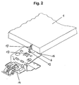
- a pin is used to fasten the connecting element 5 to the sliding floor 1 8 provided, which engages in an opening in the moving floor 1.
- the pin 8 forms a integrally formed with the pin 8 holding surface 9 a stop, so that the Moving floor 1 receives the pin 8 only to a certain depth ( Figure 2).
- the holding surface 9 and the upper surface are for a uniform force absorption the profiles 16 are arranged at a height with parallel alignment of the surfaces. It is also possible to bring the support surface 6 to a level with the holding surface 9 align and then to do without the profiles 16.
- a locking device 10 arranged on the pin 8 thus engages through a lateral one Slit in the moving floor 1 through that two elastic snap over protrude the side edge of the moving floor 1.
- the locking device 10 with the Snapping is in a recess 12 in the side wall 11 of the connecting part 5 insertable, so that the connecting part 5 after engaging the locking device 10 is pre-fixed in an assembly position.
- the connecting part 5 is provided on the side wall 11 with an exhibition 13, which can be used to attach a side wall of a drawer. It is also possible to use the exhibition 13 as a stop against the moving floor 1. Further the connecting part 5 is provided with an attachment 14 for attachment serves other components and, for example, engage in a hollow side wall can.
- the pin is in each case 8 of a connecting part 5 inserted into an opening until the underside of the moving floor 1 rests on the holding surface 9.
- the pin 8 can be provided with grooves on the circumference.
- the pin 8th be designed to be slightly elastic through the cavity 18 with a press fit in the Moving floor to be inserted.
- the push floor 1 is along at least two opposite sides provided two connecting parts 5.
- the connecting parts 5 are initially with the side walls 11 arranged parallel to the moving floor 1, so the unit consisting of moving floor 1 and connecting parts 5 without taking up much space can be transported.
- the connecting parts 5 are each folded up to the locking device 10 snaps into the recess 12 so that the connecting parts 5 are pre-fixed in an assembly position. Then one Rail 3 of a pull-out guide with the connecting parts 5 along one Side of the moving floor 1 connected. It is also possible to attach the rail 3 before attaching it the connecting parts 5 on the moving floor 1 with the connecting parts 5 connect to. Finally, the remaining components, such as side walls, front and Rear walls are mounted on the mounting arrangement.
- the fastening arrangement according to the invention is in the assembled state shown.
- To the Attachments 14 of the fastening elements 4 can be an outer side wall element 20 and mount an inner side wall element 21.
- To get out of the mounting arrangement To make a complete drawer is still on the back a foldable rear wall 22 is provided.
Landscapes
- Drawers Of Furniture (AREA)
- Connection Of Plates (AREA)
- Coupling Device And Connection With Printed Circuit (AREA)
- Light Guides In General And Applications Therefor (AREA)
- Vehicle Step Arrangements And Article Storage (AREA)
- Fittings On The Vehicle Exterior For Carrying Loads, And Devices For Holding Or Mounting Articles (AREA)
Abstract
Description
- Fig. 1
- eine perspektivische Ansicht eines Ausführungsbeispieles eines Verbindungsteiles einer erfindungsgemäßen Befestigungsanordnung;
- Fig. 2
- eine perspektivische Ansicht des Verbindungsteiles der Figur 1 in Verbindung mit einem Schubboden im vormontierten Zustand;
- Fig. 3
- eine perspektivische Ansicht des Verbindungsteiles der Figur 1 in einer vorfixierten Montageposition, und
- Fig. 4
- eine perspektivische Ansicht der Befestigungsanordnung im montierten Zustand.
Claims (10)
- Befestigungsanordnung zum Befestigen einer Schublade oder eines Schubbodens (1) an einer Ausziehführung, wobei erste Befestigungselemente (2) mit dem Schubboden (1) verbindbar sind und zweite Befestigungselemente (4) mit einer Schiene (3) der Ausziehführung verbindbar sind, und die ersten Befestigungselemente (2) zu den zweiten Befestigungselementen (4) verschwenkbar gelagert sind, dadurch gekennzeichnet, daß die Befestigungsanordnung mindestens zwei getrennt voneinander an einer Schiene (3) einer Ausziehführung montierbare Verbindungsteile (5) aufweist, die jeweils mit mindestens einem ersten und einem zweiten Befestigungselement (2, 4) versehen sind.
- Befestigungsanordnung nach Anspruch 1, dadurch gekennzeichnet, daß jedes Verbindungsteil (5) eine erste Auflagefläche (6, 16) aufweist, auf der der Schubboden (1) teilweise aufliegt, und eine zweite Auflagefläche (7) vorgesehen ist, die auf einer Schiene (3) der Ausziehführung aufliegt.
- Befestigungsanordnung nach Anspruch 1 oder 2, dadurch gekennzeichnet, daß an den ersten Befestigungselementen (2) eine Rasteinrichtung (10) vorgesehen ist, die das Verbindungsteil (5) in einer Montageposition vorfixieren kann.
- Befestigungsanordnung nach einem der Ansprüche 1 bis 3, dadurch gekennzeichnet, daß ein erstes Befestigungselement (2) einen verschwenkbar am Verbindungsteil (5) gelagerten Zapfen (8) aufweist, der in den Schubboden (1) einfügbar ist.
- Befestigungsanordnung nach einem der Ansprüche 1 bis 4, dadurch gekennzeichnet, daß an dem Zapfen (8) eine Haltefläche (9) angeformt ist, auf der der Schubboden (1) teilweise aufliegt.
- Befestigungsanordnung nach Anspruch 5, dadurch gekennzeichnet, daß die Haltefläche (9) am Zapfen (8) und die erste Auflagefläche (6, 16) bei paralleler Ausrichtung auf einer Höhe angeordnet sind.
- Befestigungsanordnung nach einem der Ansprüche 3 bis 5, dadurch gekennzeichnet, daß die Schwenkachse am Zapfen (8) etwa auf Höhe der ersten Auflagefläche (6) gebildet ist.
- Befestigungsanordnung nach einem der Ansprüche 2 bis 7, dadurch gekennzeichnet, daß zwischen der ersten Auflagefläche (6) und der zweiten Auflagefläche (7) sich eine Seitenwand (11) erstreckt, in, der eine Aussparung (12) vorgesehen ist, die mit der Rasteinrichtung (10) zusammenwirkt.
- Befestigungsanordnung nach einem der Ansprüche 1 bis 8, dadurch gekennzeichnet, daß der Zapfen (8) als Hohlprofil ausgebildet ist.
- Befestigungsanordnung nach einem der Ansprüche 1 bis 9, dadurch gekennzeichnet, daß jedes Verbindungsteil (5) einen Abschnitt aus Metall aufweist, der eine Schiene (3) der Ausziehführung zumindest teilweise umgreift, und mindestens ein erstes Befestigungselement (2) aus Kunststoff an dem Abschnitt aus Metall angeformt ist.
Applications Claiming Priority (2)
| Application Number | Priority Date | Filing Date | Title |
|---|---|---|---|
| DE19944643A DE19944643A1 (de) | 1999-09-17 | 1999-09-17 | Befestigungsanordnung |
| DE19944643 | 1999-09-17 |
Publications (2)
| Publication Number | Publication Date |
|---|---|
| EP1084657A1 true EP1084657A1 (de) | 2001-03-21 |
| EP1084657B1 EP1084657B1 (de) | 2004-02-18 |
Family
ID=7922403
Family Applications (1)
| Application Number | Title | Priority Date | Filing Date |
|---|---|---|---|
| EP00117578A Expired - Lifetime EP1084657B1 (de) | 1999-09-17 | 2000-08-16 | Befestigungsanordnung |
Country Status (6)
| Country | Link |
|---|---|
| US (1) | US6485121B1 (de) |
| EP (1) | EP1084657B1 (de) |
| AT (1) | ATE259612T1 (de) |
| BR (1) | BR0004226A (de) |
| DE (2) | DE19944643A1 (de) |
| ES (1) | ES2212948T3 (de) |
Cited By (1)
| Publication number | Priority date | Publication date | Assignee | Title |
|---|---|---|---|---|
| EP1788313A2 (de) * | 2005-11-16 | 2007-05-23 | Electrolux Home Products Corporation N.V. | Auszugsvorrichtung für ein Haushaltsgerät |
Families Citing this family (5)
| Publication number | Priority date | Publication date | Assignee | Title |
|---|---|---|---|---|
| DE20108388U1 (de) * | 2001-05-18 | 2002-09-26 | Vauth Sagel Gmbh & Co | Korbträger eines Auszugsbeschlages |
| DE20305467U1 (de) * | 2003-04-04 | 2004-08-12 | Alfit Ag | Sicherungsbeschlag |
| DE202008004100U1 (de) * | 2008-03-25 | 2009-08-06 | Paul Hettich Gmbh & Co. Kg | Teleskopierbare Auszugsführung |
| AT511417B1 (de) * | 2011-04-27 | 2018-08-15 | Blum Gmbh Julius | Schubladenseitenwand mit einer innenwand und einer aussenwand |
| DE202014104923U1 (de) * | 2014-10-16 | 2016-01-19 | Grass Gmbh | Wandelement für eine Zarge sowie Zarge, Schublade und Möbel |
Citations (5)
| Publication number | Priority date | Publication date | Assignee | Title |
|---|---|---|---|---|
| DE7317344U (de) | 1973-05-09 | 1973-08-16 | Bauknecht G Gmbh | Fuhrungsvorricntung fur Schubzuge von Mobelri oder dgl |
| DE8513783U1 (de) * | 1985-05-09 | 1985-06-27 | Standard Praezision Gmbh, 6252 Diez | Verbinder zur Befestigung eines Schubes an einer Führungsleiste |
| DE9216508U1 (de) * | 1992-12-03 | 1993-02-25 | Grass Ag, Hoechst, Vorarlberg, At | |
| DE19717184A1 (de) * | 1997-04-24 | 1998-10-29 | Grass Ag | Schublade |
| DE19726466A1 (de) | 1997-06-21 | 1998-12-24 | Lautenschlaeger Mepla Werke | Befestigungsanordnung für Schubladen-Wände am Schubladenboden |
Family Cites Families (12)
| Publication number | Priority date | Publication date | Assignee | Title |
|---|---|---|---|---|
| US3029357A (en) | 1958-05-06 | 1962-04-10 | Williams Benjamin | Drawer construction |
| US3549301A (en) | 1968-07-22 | 1970-12-22 | All Steel Equipment Inc | Drawer construction |
| US3729246A (en) | 1971-07-13 | 1973-04-24 | Evans Mfg Co Jackes | Knock-down drawer |
| DE7900396U1 (de) | 1979-01-09 | 1980-06-19 | Ninkaplast Gmbh, 4902 Bad Salzuflen | Schublade |
| AT384535B (de) | 1982-12-13 | 1987-11-25 | Blum Gmbh Julius | Ausziehfuehrungsgarnitur fuer schubladen od.dgl. |
| DE4016452A1 (de) | 1990-03-12 | 1991-09-19 | Grass Ag | Schublade mit dekorprofil |
| AT403648B (de) | 1993-03-30 | 1998-04-27 | Blum Gmbh Julius | Schubladenbausatz |
| AT401855B (de) | 1993-05-13 | 1996-12-27 | Blum Gmbh Julius | Befestigungsvorrichtung für einstellbare frontblenden von schubladen |
| AT401856B (de) * | 1993-05-13 | 1996-12-27 | Blum Gmbh Julius | Schublade |
| US5433518A (en) | 1993-11-26 | 1995-07-18 | Rubbermaid Incorporated | Drawer assembly and method therefor |
| AT409069B (de) * | 1997-07-03 | 2002-05-27 | Blum Gmbh Julius | Schubladenzarge |
| AT409072B (de) * | 1998-06-24 | 2002-05-27 | Blum Gmbh Julius | Schubladenzarge |
-
1999
- 1999-09-17 DE DE19944643A patent/DE19944643A1/de not_active Withdrawn
-
2000
- 2000-08-16 EP EP00117578A patent/EP1084657B1/de not_active Expired - Lifetime
- 2000-08-16 DE DE50005310T patent/DE50005310D1/de not_active Expired - Lifetime
- 2000-08-16 ES ES00117578T patent/ES2212948T3/es not_active Expired - Lifetime
- 2000-08-16 AT AT00117578T patent/ATE259612T1/de active
- 2000-09-15 BR BR0004226-9A patent/BR0004226A/pt not_active Application Discontinuation
- 2000-09-15 US US09/663,181 patent/US6485121B1/en not_active Expired - Fee Related
Patent Citations (5)
| Publication number | Priority date | Publication date | Assignee | Title |
|---|---|---|---|---|
| DE7317344U (de) | 1973-05-09 | 1973-08-16 | Bauknecht G Gmbh | Fuhrungsvorricntung fur Schubzuge von Mobelri oder dgl |
| DE8513783U1 (de) * | 1985-05-09 | 1985-06-27 | Standard Praezision Gmbh, 6252 Diez | Verbinder zur Befestigung eines Schubes an einer Führungsleiste |
| DE9216508U1 (de) * | 1992-12-03 | 1993-02-25 | Grass Ag, Hoechst, Vorarlberg, At | |
| DE19717184A1 (de) * | 1997-04-24 | 1998-10-29 | Grass Ag | Schublade |
| DE19726466A1 (de) | 1997-06-21 | 1998-12-24 | Lautenschlaeger Mepla Werke | Befestigungsanordnung für Schubladen-Wände am Schubladenboden |
Cited By (2)
| Publication number | Priority date | Publication date | Assignee | Title |
|---|---|---|---|---|
| EP1788313A2 (de) * | 2005-11-16 | 2007-05-23 | Electrolux Home Products Corporation N.V. | Auszugsvorrichtung für ein Haushaltsgerät |
| EP1788313A3 (de) * | 2005-11-16 | 2012-08-01 | Electrolux Home Products Corporation N.V. | Auszugsvorrichtung für ein Haushaltsgerät |
Also Published As
| Publication number | Publication date |
|---|---|
| US6485121B1 (en) | 2002-11-26 |
| EP1084657B1 (de) | 2004-02-18 |
| ES2212948T3 (es) | 2004-08-16 |
| ATE259612T1 (de) | 2004-03-15 |
| DE19944643A1 (de) | 2001-03-22 |
| DE50005310D1 (de) | 2004-03-25 |
| BR0004226A (pt) | 2001-04-10 |
Similar Documents
| Publication | Publication Date | Title |
|---|---|---|
| EP1084655B1 (de) | Befestigungsanordnung | |
| EP2059145B1 (de) | Schubkasten | |
| EP3585211B1 (de) | Anordnung mit möbelteile und verbindungsstift | |
| EP3561207B1 (de) | Verbindungsmittel und möbelteil | |
| EP3579726A1 (de) | Schubkasten | |
| AT413320B (de) | Schublade | |
| EP1084657B1 (de) | Befestigungsanordnung | |
| DE19733435A1 (de) | Bürotisch | |
| EP1157636A1 (de) | Befestigungsanordnung | |
| WO2012068598A1 (de) | Behältnisschiene für einen schubladenbehälter | |
| EP3773074B1 (de) | Schubsystem mit auszugsführung an welchem unterschiedliche schubkastensystemen montierbar sind | |
| EP2260742B1 (de) | Möbelsystem | |
| EP1084659B1 (de) | Montageeinheit | |
| EP1084656B1 (de) | Befestigungsanordnung | |
| EP1873340B1 (de) | Türanlage | |
| DE202008006607U1 (de) | Rückwandverbinder und Möbel | |
| EP3967890B1 (de) | Verbindungselement für ein möbelstück, stecksystem mit einem solchen verbindungselement und ein verfahren zur montage eines möbelstücks | |
| EP4021246B1 (de) | Vorrichtung zur fixierung eines schubkastens | |
| AT393204B (de) | Moebel mit mindestens einem schubkasten | |
| AT398515B (de) | Beschlag zur lösbaren halterung | |
| EP1228719A1 (de) | Schubkasten mit lösbarer Frontblende | |
| DE102007009501A1 (de) | Bodenträgerbeschlag für Möbel mit Glasböden | |
| DE3011843A1 (de) | Verbindungs- und traegerelement fuer moebel | |
| EP1092068B1 (de) | Vorrichtung zur befestigung von bauteilen | |
| EP1254993A1 (de) | Blechteil zum Halten von Profilschienen |
Legal Events
| Date | Code | Title | Description |
|---|---|---|---|
| PUAI | Public reference made under article 153(3) epc to a published international application that has entered the european phase |
Free format text: ORIGINAL CODE: 0009012 |
|
| AK | Designated contracting states |
Kind code of ref document: A1 Designated state(s): AT BE CH CY DE DK ES FI FR GB GR IE IT LI LU MC NL PT SE |
|
| AX | Request for extension of the european patent |
Free format text: AL;LT;LV;MK;RO;SI |
|
| 17P | Request for examination filed |
Effective date: 20010911 |
|
| AKX | Designation fees paid |
Free format text: AT BE CH CY DE DK ES FI FR GB GR IE IT LI LU MC NL PT SE |
|
| 17Q | First examination report despatched |
Effective date: 20021024 |
|
| GRAP | Despatch of communication of intention to grant a patent |
Free format text: ORIGINAL CODE: EPIDOSNIGR1 |
|
| GRAS | Grant fee paid |
Free format text: ORIGINAL CODE: EPIDOSNIGR3 |
|
| GRAA | (expected) grant |
Free format text: ORIGINAL CODE: 0009210 |
|
| AK | Designated contracting states |
Kind code of ref document: B1 Designated state(s): AT BE CH CY DE DK ES FI FR GB GR IE IT LI LU MC NL PT SE |
|
| PG25 | Lapsed in a contracting state [announced via postgrant information from national office to epo] |
Ref country code: CY Free format text: LAPSE BECAUSE OF FAILURE TO SUBMIT A TRANSLATION OF THE DESCRIPTION OR TO PAY THE FEE WITHIN THE PRESCRIBED TIME-LIMIT Effective date: 20040218 |
|
| REG | Reference to a national code |
Ref country code: GB Ref legal event code: FG4D Free format text: NOT ENGLISH |
|
| REG | Reference to a national code |
Ref country code: CH Ref legal event code: EP |
|
| REG | Reference to a national code |
Ref country code: IE Ref legal event code: FG4D Free format text: GERMAN |
|
| REF | Corresponds to: |
Ref document number: 50005310 Country of ref document: DE Date of ref document: 20040325 Kind code of ref document: P |
|
| PG25 | Lapsed in a contracting state [announced via postgrant information from national office to epo] |
Ref country code: GR Free format text: LAPSE BECAUSE OF FAILURE TO SUBMIT A TRANSLATION OF THE DESCRIPTION OR TO PAY THE FEE WITHIN THE PRESCRIBED TIME-LIMIT Effective date: 20040518 Ref country code: DK Free format text: LAPSE BECAUSE OF FAILURE TO SUBMIT A TRANSLATION OF THE DESCRIPTION OR TO PAY THE FEE WITHIN THE PRESCRIBED TIME-LIMIT Effective date: 20040518 |
|
| REG | Reference to a national code |
Ref country code: SE Ref legal event code: TRGR |
|
| GBT | Gb: translation of ep patent filed (gb section 77(6)(a)/1977) |
Effective date: 20040519 |
|
| PG25 | Lapsed in a contracting state [announced via postgrant information from national office to epo] |
Ref country code: LU Free format text: LAPSE BECAUSE OF NON-PAYMENT OF DUE FEES Effective date: 20040816 Ref country code: FI Free format text: LAPSE BECAUSE OF NON-PAYMENT OF DUE FEES Effective date: 20040816 Ref country code: IE Free format text: LAPSE BECAUSE OF NON-PAYMENT OF DUE FEES Effective date: 20040816 |
|
| REG | Reference to a national code |
Ref country code: ES Ref legal event code: FG2A Ref document number: 2212948 Country of ref document: ES Kind code of ref document: T3 |
|
| PG25 | Lapsed in a contracting state [announced via postgrant information from national office to epo] |
Ref country code: SE Free format text: LAPSE BECAUSE OF NON-PAYMENT OF DUE FEES Effective date: 20040817 |
|
| PG25 | Lapsed in a contracting state [announced via postgrant information from national office to epo] |
Ref country code: LI Free format text: LAPSE BECAUSE OF NON-PAYMENT OF DUE FEES Effective date: 20040831 Ref country code: BE Free format text: LAPSE BECAUSE OF NON-PAYMENT OF DUE FEES Effective date: 20040831 Ref country code: MC Free format text: LAPSE BECAUSE OF NON-PAYMENT OF DUE FEES Effective date: 20040831 Ref country code: CH Free format text: LAPSE BECAUSE OF NON-PAYMENT OF DUE FEES Effective date: 20040831 |
|
| ET | Fr: translation filed | ||
| PLBE | No opposition filed within time limit |
Free format text: ORIGINAL CODE: 0009261 |
|
| STAA | Information on the status of an ep patent application or granted ep patent |
Free format text: STATUS: NO OPPOSITION FILED WITHIN TIME LIMIT |
|
| 26N | No opposition filed |
Effective date: 20041119 |
|
| BERE | Be: lapsed |
Owner name: PAUL *HETTICH G.M.B.H. & CO. Effective date: 20040831 |
|
| EUG | Se: european patent has lapsed | ||
| REG | Reference to a national code |
Ref country code: CH Ref legal event code: PL |
|
| REG | Reference to a national code |
Ref country code: IE Ref legal event code: MM4A |
|
| BERE | Be: lapsed |
Owner name: PAUL *HETTICH G.M.B.H. & CO. Effective date: 20040831 |
|
| PG25 | Lapsed in a contracting state [announced via postgrant information from national office to epo] |
Ref country code: PT Free format text: LAPSE BECAUSE OF NON-PAYMENT OF DUE FEES Effective date: 20040718 |
|
| PGFP | Annual fee paid to national office [announced via postgrant information from national office to epo] |
Ref country code: NL Payment date: 20140821 Year of fee payment: 15 Ref country code: DE Payment date: 20140821 Year of fee payment: 15 |
|
| PGFP | Annual fee paid to national office [announced via postgrant information from national office to epo] |
Ref country code: AT Payment date: 20140620 Year of fee payment: 15 Ref country code: ES Payment date: 20140827 Year of fee payment: 15 Ref country code: FR Payment date: 20140819 Year of fee payment: 15 Ref country code: GB Payment date: 20140821 Year of fee payment: 15 |
|
| PGFP | Annual fee paid to national office [announced via postgrant information from national office to epo] |
Ref country code: IT Payment date: 20140827 Year of fee payment: 15 |
|
| REG | Reference to a national code |
Ref country code: DE Ref legal event code: R119 Ref document number: 50005310 Country of ref document: DE |
|
| REG | Reference to a national code |
Ref country code: AT Ref legal event code: MM01 Ref document number: 259612 Country of ref document: AT Kind code of ref document: T Effective date: 20150816 |
|
| GBPC | Gb: european patent ceased through non-payment of renewal fee |
Effective date: 20150816 |
|
| PG25 | Lapsed in a contracting state [announced via postgrant information from national office to epo] |
Ref country code: IT Free format text: LAPSE BECAUSE OF NON-PAYMENT OF DUE FEES Effective date: 20150816 |
|
| REG | Reference to a national code |
Ref country code: NL Ref legal event code: MM Effective date: 20150901 |
|
| PG25 | Lapsed in a contracting state [announced via postgrant information from national office to epo] |
Ref country code: AT Free format text: LAPSE BECAUSE OF NON-PAYMENT OF DUE FEES Effective date: 20150816 |
|
| REG | Reference to a national code |
Ref country code: FR Ref legal event code: ST Effective date: 20160429 |
|
| PG25 | Lapsed in a contracting state [announced via postgrant information from national office to epo] |
Ref country code: NL Free format text: LAPSE BECAUSE OF NON-PAYMENT OF DUE FEES Effective date: 20150901 |
|
| PG25 | Lapsed in a contracting state [announced via postgrant information from national office to epo] |
Ref country code: GB Free format text: LAPSE BECAUSE OF NON-PAYMENT OF DUE FEES Effective date: 20150816 Ref country code: DE Free format text: LAPSE BECAUSE OF NON-PAYMENT OF DUE FEES Effective date: 20160301 |
|
| PG25 | Lapsed in a contracting state [announced via postgrant information from national office to epo] |
Ref country code: FR Free format text: LAPSE BECAUSE OF NON-PAYMENT OF DUE FEES Effective date: 20150831 |
|
| REG | Reference to a national code |
Ref country code: ES Ref legal event code: FD2A Effective date: 20160929 |
|
| PG25 | Lapsed in a contracting state [announced via postgrant information from national office to epo] |
Ref country code: ES Free format text: LAPSE BECAUSE OF NON-PAYMENT OF DUE FEES Effective date: 20150817 |