EP1083284B1 - Türgriffanordnung für ein Kraftfahrzeug-Türschliesssystem mit Passive Entry-Funktion - Google Patents
Türgriffanordnung für ein Kraftfahrzeug-Türschliesssystem mit Passive Entry-Funktion Download PDFInfo
- Publication number
- EP1083284B1 EP1083284B1 EP00117963A EP00117963A EP1083284B1 EP 1083284 B1 EP1083284 B1 EP 1083284B1 EP 00117963 A EP00117963 A EP 00117963A EP 00117963 A EP00117963 A EP 00117963A EP 1083284 B1 EP1083284 B1 EP 1083284B1
- Authority
- EP
- European Patent Office
- Prior art keywords
- door handle
- door
- outside
- handle
- motor vehicle
- Prior art date
- Legal status (The legal status is an assumption and is not a legal conclusion. Google has not performed a legal analysis and makes no representation as to the accuracy of the status listed.)
- Expired - Lifetime
Links
- 230000033001 locomotion Effects 0.000 claims abstract description 25
- 230000007246 mechanism Effects 0.000 claims abstract description 7
- 238000006073 displacement reaction Methods 0.000 claims abstract 8
- 238000010276 construction Methods 0.000 claims description 4
- 230000004913 activation Effects 0.000 claims 2
- 238000006243 chemical reaction Methods 0.000 description 16
- 238000013475 authorization Methods 0.000 description 8
- 230000009471 action Effects 0.000 description 5
- 238000013459 approach Methods 0.000 description 4
- 230000008878 coupling Effects 0.000 description 3
- 238000010168 coupling process Methods 0.000 description 3
- 238000005859 coupling reaction Methods 0.000 description 3
- 230000007704 transition Effects 0.000 description 3
- 230000005540 biological transmission Effects 0.000 description 2
- 238000009434 installation Methods 0.000 description 2
- 230000008859 change Effects 0.000 description 1
- 210000001520 comb Anatomy 0.000 description 1
- 238000011161 development Methods 0.000 description 1
- 230000018109 developmental process Effects 0.000 description 1
- 239000000428 dust Substances 0.000 description 1
- 230000000694 effects Effects 0.000 description 1
- 238000010030 laminating Methods 0.000 description 1
- 238000003475 lamination Methods 0.000 description 1
- 230000007257 malfunction Effects 0.000 description 1
- 230000005855 radiation Effects 0.000 description 1
- 230000004044 response Effects 0.000 description 1
- 230000001960 triggered effect Effects 0.000 description 1
- 230000002618 waking effect Effects 0.000 description 1
Images


Classifications
-
- E—FIXED CONSTRUCTIONS
- E05—LOCKS; KEYS; WINDOW OR DOOR FITTINGS; SAFES
- E05B—LOCKS; ACCESSORIES THEREFOR; HANDCUFFS
- E05B85/00—Details of vehicle locks not provided for in groups E05B77/00 - E05B83/00
- E05B85/10—Handles
-
- E—FIXED CONSTRUCTIONS
- E05—LOCKS; KEYS; WINDOW OR DOOR FITTINGS; SAFES
- E05B—LOCKS; ACCESSORIES THEREFOR; HANDCUFFS
- E05B77/00—Vehicle locks characterised by special functions or purposes
- E05B77/42—Means for damping the movement of lock parts, e.g. slowing down the return movement of a handle
-
- E—FIXED CONSTRUCTIONS
- E05—LOCKS; KEYS; WINDOW OR DOOR FITTINGS; SAFES
- E05B—LOCKS; ACCESSORIES THEREFOR; HANDCUFFS
- E05B81/00—Power-actuated vehicle locks
- E05B81/54—Electrical circuits
- E05B81/64—Monitoring or sensing, e.g. by using switches or sensors
- E05B81/76—Detection of handle operation; Detection of a user approaching a handle; Electrical switching actions performed by door handles
- E05B81/78—Detection of handle operation; Detection of a user approaching a handle; Electrical switching actions performed by door handles as part of a hands-free locking or unlocking operation
Definitions
- the invention relates to a door handle arrangement for a motor vehicle door locking system with passive entry function with the characteristics of the generic term of claim 1.
- a motor vehicle door locking system with passive entry function also "electronic Key”differs from that previously explained classic motor vehicle door locking system in that on the remote control module no handling, so no button press has to be made, to unlock the motor vehicle lock when approaching the motor vehicle. Rather, all of this happens by itself simply when the operator approaches to the motor vehicle.
- a motor vehicle door locking system with a passive entry function is required for the control electronics a specific reaction phase, which is based on a start-up interval, to activate the system when the remote control module approaches, an authorization check interval, based on the operator the coding of the exchanged between the remote control module and control electronics Check signals for their authorization, and finally that actual interval of action in which the action takes place, in particular the Unlocking the motor vehicle lock is carried out.
- a specific reaction phase which is based on a start-up interval, to activate the system when the remote control module approaches, an authorization check interval, based on the operator the coding of the exchanged between the remote control module and control electronics Check signals for their authorization, and finally that actual interval of action in which the action takes place, in particular the Unlocking the motor vehicle lock is carried out.
- the duration of the reaction phase of approx. 150 ms is compared to conventional Motor vehicle door locking systems perceived as long if one the start-up interval only starts when the outside door handle is actuated.
- EP-A-927 803 and EP-A-916 789 deal with this problem.
- Such one Motor vehicle door locking system with passive entry function is also known from DE-A-197 52 974. From a door handle assembly for one such a motor vehicle door locking system is based on the teaching of the invention.
- Another approach is the start-up interval of the control electronics not to start only when the outer door handle is actuated, but already an operator's hand approaching the outside door handle to start the start-up interval.
- a proximity sensor DE - A - 197 52 974; DE A - 196 17 038
- the start of the start-up interval of the control electronics so the "waking up" of the control electronics takes place so far before the actual one Pulling the outer door handle that the start-up interval and usually also that Authorization check interval are already completed when the outside door handle is actually moved by the operator's hand.
- proximity sensors have a comparatively high one Quiescent current, on the other hand, it is difficult to have a stable, clear response threshold adjust. External influences such as rain, snow, dust and Dirt change the measured values, especially with capacitive proximity sensors very. Finally, with proximity sensors, the problem is through not to be overlooked they emitted electromagnetic interference radiation. Therefore, despite the difficulties discussed above, the motor vehicle door locking systems have with passive entry function, where only one Actuation of the outside door handle by the hand of an operator Start-up interval of the control electronics starts, considerable advantages.
- the invention is based on the problem of a door handle arrangement for to specify a motor vehicle door locking system with a passive entry function, which offers the prerequisites that a longer reaction phase of the Control electronics not perceived by the operator as disturbing becomes.
- the motor vehicle 1 shown schematically in FIG. 1 has a motor vehicle door locking system on where the various motor vehicle locks 2 for motor vehicle doors and motor vehicle flaps schematically with their Installation positions are indicated.
- Each motor vehicle lock 2 is motor-driven, preferably by electric motor, unlockable and lockable.
- the motor vehicle lock 2 additionally the possibility of a motorized opening, i.e. lifting the pawl by means of an opening drive. In this case unlocking and locking can only be done by circuitry.
- Another variant is also the equipment of the motor vehicle locks 2 with an auxiliary locking drive that is identical to or from the opening drive this can be separated.
- the state of the art be referred (DE - A - 196 29 709 etc.).
- Control electronics 3 are indicated in the motor vehicle door locking system is indicated here as central control electronics, but it is also decentralized to everyone the motor vehicle locks 2 can be assigned. It is planned to continue a hood lock 4 to be operated by means of a key for the bonnet of the motor vehicle and a remote control module 5, the passive Entry chip card is executed.
- the control electronics 3 cooperate overall a passive entry function, ie with an "electronic key". In this respect, too, reference may be made to the prior art mentioned above become.
- the motor vehicle body can be recognized by the respective motor vehicle door an outside door handle 6 and on the driver's door a lock cylinder 7 for an actuation with a mechanical key 8, such an actuation in an emergency (emergency release and, if necessary, emergency opening).
- control electronics 3 have a reaction phase with a start-up interval, Authorization check interval and action interval, especially for unlocking of the motor vehicle lock 2.
- Fig. 2 shows a typical Door handle assembly 9 of a motor vehicle door locking system in question standing type with the outside door handle 6 and the lock cylinder 7.
- a door handle bearing 10 firmly attached to the motor vehicle door in the illustrated embodiment consists of two bearing parts, namely a bearing part 10a, which also includes the lock cylinder 7, and a bearing part 10b, which contains the pivot bearing of the outer handle 6.
- the outside door handle 6 is adjustable on the door handle bearing 10, in the illustrated and preferred Embodiment pivotally mounted.
- the swivel bearing can not only about a vertical axis as in the illustrated embodiment, but also around a horizontal axis as in the prior art DE - A - 197 52 974 can be realized.
- Other adjustment constructions too for the outside door handle 6, for example also a push handle or a slide lever are conceivable.
- the prerequisite is that the outer door handle 6 relative to the door handle bearing 10 from a rest position by a maximum adjustment range to an actuation position is adjustable.
- a switch 11 is arranged, the actuation of the outer door handle 6 from the Rest position detected.
- the switch 11 is an electromechanical in the illustrated embodiment Microswitch, any other form of switch, for example, too Non-contact switches such as Hall sensors can be used here become.
- the outer door handle 6 an adjustment of an outer operating lever 12 a lock mechanism for opening the motor vehicle door.
- the outer door handle 6 is assigned a coupling element 13, which the outer operating lever 12 of the lock mechanism.
- the outer operating lever 12 of the lock mechanism For such constructions may be referred to the state of the art.
- the coupling element 13 need not have the hook shape shown in FIG. 3, it can also have the form of a rotary transmission element or the like.
- Various Solutions for the mechanical coupling of the outside door handle 6 to the lock mechanism are known in the prior art and can also in the present case.
- a lost motion connection 15 between the outer door handle 6 and the outer operating lever 12 is realized in construction.
- a lost motion connection 15 can be provided, for example, by an elongated hole arrangement, a toggle lever arrangement or the like can be realized. Is particularly compact a lost motion connection 15 is realized as in the illustrated embodiment when it is designed as a telescopic connection. That the outside operating lever 12 assigned telescopic member 16 of the lost motion connection 15 does not move here until at least one further telescopic member 17 has covered a maximum adjustment distance. It is recommended that the lost motion connection 15, in particular the telescopic connection, with a spring element 18 is biased into the rest position.
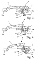
- FIG. 3 shows the outer door handle 6 in its rest position on the door handle bearing 10. If the outer door handle 6 is now pulled, the transition according to Fig. 4. It can be seen that first the microswitch 11 on the door handle bearing 10, namely on its bearing part 10a, immediately after actuation of the outer door handle 6 is operated. The switch 11 starts the reaction phase of the control electronics 3. While the outer door handle 6 is moving, the Control electronics 3 the start-up interval, the authorization check interval and finally the interval of action - unlocking the motor vehicle lock 2 - from. While moving the outside door handle 6 over a first part of it Adjustment path is only the telescopic member 17 on the outside door handle 6 itself moves, the spring element 18 is tensioned. In the transition from FIG.
- FIG. 4 5 since the telescopic member 17 has reached a stop, the telescopic member 16 connected to the outer operating lever 12 moves, until the outer door handle 6 then reaches its maximum adjustment path in FIG. 5 Has.
- the transition from FIG. 4 to FIG. 5 represents the adjustment path of the outer operating lever 12.
- the reaction phase of the control electronics 3 completed, the motor vehicle lock 2 is unlocked, the motor vehicle door is ultimately by the movement of the outer operating lever 12 open.
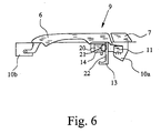
- the outer actuation lever 12 is thus omitted. As indicated in FIG. 6, in addition is here by moving the outer door handle 6 over the switch 11 triggered the granting of access authorization. Then takes place the signal of an opening switch 14 and the access authorization is granted the function "open by wire", in particular that Lifting the pawl initiated by an auxiliary opening drive.
- FIG. 6 shows a further exemplary embodiment of an inventive one Door handle arrangement 9, characterized in that the adjustment movement of the outside door handle is slowed down by means of a braking device 20 becomes.
- the adjustment path of the outside door handle 6 is not artificial extended and thereby conceals the reaction phase of the control electronics 3, but the adjustment of the outer door handle 6 is deliberately slowed down.
- the braking device 20 can also be used with the previously explained Combine telescope arrangement of the first embodiment.
- the embodiment of a braking device shown here is particularly expedient 20 if they do the adjustment movement of the outer door handle 6 slows down, but the required actuation force is not or only insignificantly increased compared to conventional outside door handles.
- the two previously described embodiments of an inventive Door handle assembly 9 are both characterized in that they are in the direction of the adjustment movement of the outer door handle 6 only one relative have shallow depth. This facilitates installation in modern motor vehicle doors with a window guide near the outer skin of the motor vehicle door. In both alternatives of the invention, the required one is reached Laminating the reaction phase of the control electronics 3 without inside Motor vehicle door to need an excessively large adjustment. The latter would also be for the normal arrangement of an external operating lever 12 hardly feasible within the lock mechanism.
Landscapes
- Lock And Its Accessories (AREA)
Description
- Fig. 1
- in einer schematischen und perspektivischen Ansicht ein Kraftfahrzeug mit einem Türschließsystem der in Rede stehenden Art,
- Fig. 2
- eine Türgriffanordnung bei einem Kraftfahrzeug-Türschließsystem gemäß Fig. 1,
- Fig. 3
- ein erstes Ausführungsbeispiel einer erfindungsgemäßen Türgriffanordnung, den Türaußengriff in Ruhestellung,
- Fig. 4
- in Fig. 3 entsprechender Darstellung eine Türgriffanordnung mit dem Türaußengriff in einer Mittelstellung,
- Fig. 5
- in einer Fig. 3 entsprechenden Darstellung die Türgriffanordnung mit dem Türaußengriff nach Zurücklegen des maximalen Verstellweges in seiner Betätigungsstellung,
- Fig. 6
- ein weiteres Ausführungsbeispiel einer erfindungsgemäßen Türgriffanordnung in einer Fig. 3 entsprechenden Darstellung, den Türaußengriff also in Ruhestellung.
Claims (5)
- Türgriffanordnung für ein Kraftfahrzeug-Türschließsystem mit Passive Entry-Funktion,
mit einem an einer Kraftfahrzeugtür fest angebrachten Türgrifflager (10), das ggf. auch aus zwei Lagerteilen (10a, 10b) besteht, und einem am Türgrifflager (10) verstellbar, insbesondere schwenkbar gelagerten Türaußengriff(6),
wobei der Türaußengriff (6) gegenüber dem Türgrifflager (10) aus einer Ruhestellung um einen maximalen Verstellweg bis in eine Betätigungsstellung verstellbar ist,
wobei am Türaußengriff (6) oder am Türgrifflager (10) ein Schalter (11) angeordnet ist, der eine Betätigung des Türaußengriffes (6) aus der Ruhestellung erfaßt,
wobei durch die Verstellung des Türaußengriffes (6) eine Verstellung eines Außenbetätigungshebels (12) einer Schloßmechanik oder eine elektrische Funktion zum Öffnen der Kraftfahrzeugtür erfolgt und
wobei die Verstellbewegung des Türaußengriffes (6) mit einer Verzögerung auf den Außenbetätigungshebel (12) oder einen Öffnungsschalter (14) übertragen wird und die Verzögerung durch eine Totgangverbindung (15) zwischen dem Türaußengriff (6) und dem Außenbetätigungshebel (12) bzw. dem Öffnungsschalter (14) konstruktiv realisiert ist,
dadurch gekennzeichnet, daß die Totgangverbindung (15) als Teleskopverbindung ausgeführt ist, deren dem Außenbetätigungshebel (12) zugeordnetes Teleskopglied (16) sich erst bewegt, wenn mindestens ein weiteres Teleskopglied (17) einen bestimmten Verstellweg zurückgelegt hat. - Türgriffanordnung nach Anspruch 1, dadurch gekennzeichnet, daß die Teleskopverbindung mit einem Federelement (18) in die Ruhestellung vorgespannt ist.
- Türgriffanordnung für ein Kraftfahrzeug-Türschließsystem mit Passive Entry-Funktion,
mit einem an einer Kraftfahrzeugtür fest angebrachten Türgrifflager (10), das ggf. auch aus zwei Lagerteilen (10a, 10b) besteht, und einem am Türgrifflager (10) verstellbar, insbesondere schwenkbar gelagerten Türaußengriff (6),
wobei der Türaußengriff (6) gegenüber dem Türgrifflager (10) aus einer Ruhestellung um einen maximalen Verstellweg bis in eine Betätigungsstellung verstellbar ist,
wobei am Türaußengriff (6) oder am Türgrifflager (10) ein Schalter (11) angeordnet ist, der eine Betätigung des Türaußengriffes (6) aus der Ruhestellung erfaßt,
wobei durch die Verstellung des Türaußengriffes (6) eine Verstellung eines Außenbetätigungshebels (12) einer Schloßmechanik oder eine elektrische Funktion zum Öffnen der Kraftfahrzeugtür erfolgt,
wobei die Verstellbewegung des Türaußengriffes (6) mittels einer Bremseinrichtung (20) verlangsamt wird, ohne die notwendige Betätigungskraft zu erhöhen,
ggf. auch nach Anspruch 1 oder 2,
dadurch gekennzeichnet, daß die Bremseinrichtung (20) als Viskositätsbremse ausgeführt ist. - Türgriffanordnung nach Anspruch 3, dadurch gekennzeichnet, daß der Türaußengriff (6) mit einem Federelement in die Ruhestellung vorgespannt ist.
- Türgriffanordnung nach Anspruch 3 oder 4, dadurch gekennzeichnet, daß die Bremseinrichtung (20) für die Rückkehrbewegung des Türaußengriffes (6) aus der Betätigungsstellung in die Ruhestellung einen Freilauf aufweist.
Applications Claiming Priority (2)
| Application Number | Priority Date | Filing Date | Title |
|---|---|---|---|
| DE19942481 | 1999-09-07 | ||
| DE19942481A DE19942481A1 (de) | 1999-09-07 | 1999-09-07 | Türgriffanordnung für ein Kraftfahrzheug-Türschliesssystem mit Passive Entry-Funktion |
Publications (2)
| Publication Number | Publication Date |
|---|---|
| EP1083284A1 EP1083284A1 (de) | 2001-03-14 |
| EP1083284B1 true EP1083284B1 (de) | 2004-03-10 |
Family
ID=7920971
Family Applications (1)
| Application Number | Title | Priority Date | Filing Date |
|---|---|---|---|
| EP00117963A Expired - Lifetime EP1083284B1 (de) | 1999-09-07 | 2000-08-22 | Türgriffanordnung für ein Kraftfahrzeug-Türschliesssystem mit Passive Entry-Funktion |
Country Status (4)
| Country | Link |
|---|---|
| EP (1) | EP1083284B1 (de) |
| AT (1) | ATE261537T1 (de) |
| DE (2) | DE19942481A1 (de) |
| ES (1) | ES2218037T3 (de) |
Families Citing this family (12)
| Publication number | Priority date | Publication date | Assignee | Title |
|---|---|---|---|---|
| FR2823243B1 (fr) * | 2001-04-04 | 2004-02-20 | Valeo Securite Habitacle | Ensemble de commande d'une serrure d'ouvrant de vehicule automobile |
| DE10300572A1 (de) * | 2003-01-10 | 2004-07-22 | Daimlerchrysler Ag | Türgriff und Schließsystem für eine Fahrzeugtür |
| US20060005590A1 (en) * | 2004-07-12 | 2006-01-12 | Lear Corporation | Mechanical door handle switch assembly with a dampening mechanism |
| GB2416187A (en) * | 2004-07-12 | 2006-01-18 | Lear Corp | Vehicle handle-operated switch assembly with handle dampening |
| US20060010943A1 (en) * | 2004-07-13 | 2006-01-19 | Lear Corporation | Mechanical handle switch assembly |
| DE102004057620A1 (de) * | 2004-11-29 | 2006-06-01 | Brose Fahrzeugteile Gmbh & Co. Kommanditgesellschaft, Coburg | Vorrichtung zum Verbinden eines Außengriffs mit einem Schließelement bei Kraftfahrzeugen |
| DE102005031479A1 (de) * | 2005-07-04 | 2007-01-11 | Conti Temic Microelectronic Gmbh | Schließsystem |
| FR2905400B1 (fr) * | 2006-08-29 | 2010-09-24 | Peugeot Citroen Automobiles Sa | Dispositif de commande de l'ouverture d'un ouvrant de vehicule automobile. |
| ITMI20072004A1 (it) * | 2007-10-17 | 2009-04-18 | Valeo Sicurezza Abitacolo Spa | Maniglia per veicoli con sensore perfezionato |
| FR2953782B1 (fr) * | 2009-12-15 | 2012-01-13 | Valeo Securite Habitacle | Dispositif d'activation de systeme mains-libres |
| FR2955604A1 (fr) * | 2010-01-25 | 2011-07-29 | Renault Sa | Poignee de portiere comportant un interrupteur actionne par une partie mobile |
| DE102015101630B4 (de) * | 2015-02-05 | 2025-12-24 | Dr. Ing. H.C. F. Porsche Aktiengesellschaft | Türgriffeinrichtung |
Family Cites Families (4)
| Publication number | Priority date | Publication date | Assignee | Title |
|---|---|---|---|---|
| DE19521024B4 (de) * | 1995-06-13 | 2004-12-16 | Brose Schließsysteme GmbH & Co.KG | Verfahren zur Betätigung eines Kraftfahrzeug-Türschließsystems |
| DE19750023A1 (de) * | 1997-11-12 | 1999-05-27 | Bosch Gmbh Robert | Einrichtung zum Verriegeln und Entriegeln eines Türschlosses |
| US6072403A (en) * | 1997-12-05 | 2000-06-06 | Kabushiki Kaisha Tokai Rika Denki Seisakusho | Door unlocking device for vehicle |
| EP1001116B1 (de) * | 1998-11-13 | 2005-06-08 | Brose Schliesssysteme GmbH & Co. KG | Verfahren zur Betätigung eines Kraftfahrzeug-Türschliesssystems |
-
1999
- 1999-09-07 DE DE19942481A patent/DE19942481A1/de not_active Ceased
-
2000
- 2000-08-22 ES ES00117963T patent/ES2218037T3/es not_active Expired - Lifetime
- 2000-08-22 EP EP00117963A patent/EP1083284B1/de not_active Expired - Lifetime
- 2000-08-22 DE DE50005583T patent/DE50005583D1/de not_active Expired - Fee Related
- 2000-08-22 AT AT00117963T patent/ATE261537T1/de not_active IP Right Cessation
Also Published As
| Publication number | Publication date |
|---|---|
| ATE261537T1 (de) | 2004-03-15 |
| EP1083284A1 (de) | 2001-03-14 |
| DE19942481A1 (de) | 2001-04-05 |
| DE50005583D1 (de) | 2004-04-15 |
| ES2218037T3 (es) | 2004-11-16 |
Similar Documents
| Publication | Publication Date | Title |
|---|---|---|
| DE69925089T2 (de) | Handhabe für Kraftfahrzeugschloss | |
| EP3739155B1 (de) | Türgriffanordnung | |
| EP1268959B1 (de) | Zugangssystem für ein fahrzeug | |
| EP2032783B1 (de) | Betätigungsvorrichtung | |
| EP1512814B1 (de) | Kraftfahrzeug-Türschliesssystem und Türgriff | |
| EP1304433B1 (de) | Kraftfahrzeug-Türschloss mit voneinander getrennter Schliesseinheit und Steuereinheit | |
| DE69710147T2 (de) | Betätigungsgriff zum Öffnen eines Schlosses einer Kraftfahrzeugöffnung | |
| DE102019105729A1 (de) | Klappe für ein griffloses Verschlusspaneel in Kraftfahrzeugen | |
| EP3194695A1 (de) | Türgriffanordnung für ein kraftfahrzeug | |
| EP2535489A2 (de) | Handhabe eines beweglichen Teils mit einer Elektronikbaugruppe, die an unterschiedlichen Bauteilen angeordnet ist | |
| EP1083282A2 (de) | Kraftfahrzeug-Türschliesssystem mit Passive Entry-Funktion und Schnellentriegelung | |
| EP1283934B1 (de) | Kraftfahrzeug-türschliesssystem mit schnellentriegelung | |
| EP1083284A1 (de) | Türgriffanordnung für ein Kraftfahrzeug-Türschliesssystem mit Passive Entry-Funktion | |
| DE102016104779A1 (de) | Anti-Panikdruckstange mit Antriebseinrichtung | |
| DE19957087B4 (de) | Kraftfahrzeug-Türschliesssystem | |
| EP1937921B1 (de) | Vorrichtung zum öffnen von schlössern an türen oder klappen von fahrzeugen | |
| EP0693603A1 (de) | Entriegelungsvorrichtung für einen Kraftfahrzeugtürverschluss | |
| DE10151022A1 (de) | Kraftfahrzeug-Türschloß mit voneinander getrennter Schließeinheit und Steuereinheit | |
| EP1908899A2 (de) | Schließanlage | |
| DE10151870B4 (de) | Vorrichtung zur Betätigung eines Verschlusses von Türen oder Klappen, insbesondere an Fahrzeugen | |
| DE10206700A1 (de) | Gebäudetüranordnung | |
| DE102006005753A1 (de) | Schließsystem | |
| DE19635415C2 (de) | Kopplungseinrichtung für ein Schloß, insbesondere ein Türschloß eines Kraftfahrzeuges | |
| EP1079055B1 (de) | Kraftfahrzeug-Türschliesssystem mit Passive Entry-Funktion | |
| EP0328607A1 (de) | Schloss für kraftfahrzeugtüren, insbesondere für heckklappen |
Legal Events
| Date | Code | Title | Description |
|---|---|---|---|
| PUAI | Public reference made under article 153(3) epc to a published international application that has entered the european phase |
Free format text: ORIGINAL CODE: 0009012 |
|
| AK | Designated contracting states |
Kind code of ref document: A1 Designated state(s): AT BE CH CY DE DK ES FI FR GB GR IE IT LI LU MC NL PT SE |
|
| AX | Request for extension of the european patent |
Free format text: AL;LT;LV;MK;RO;SI |
|
| 17P | Request for examination filed |
Effective date: 20010914 |
|
| AKX | Designation fees paid |
Free format text: AT BE CH CY DE DK ES FI FR GB GR IE IT LI LU MC NL PT SE |
|
| REG | Reference to a national code |
Ref country code: GB Ref legal event code: FG4D Free format text: NOT ENGLISH |
|
| GRAP | Despatch of communication of intention to grant a patent |
Free format text: ORIGINAL CODE: EPIDOSNIGR1 |
|
| RAP1 | Party data changed (applicant data changed or rights of an application transferred) |
Owner name: BROSE SCHLIESSSYSTEME GMBH & CO. KG |
|
| GRAS | Grant fee paid |
Free format text: ORIGINAL CODE: EPIDOSNIGR3 |
|
| GRAA | (expected) grant |
Free format text: ORIGINAL CODE: 0009210 |
|
| AK | Designated contracting states |
Kind code of ref document: B1 Designated state(s): AT BE CH CY DE DK ES FI FR GB GR IE IT LI LU MC NL PT SE |
|
| PG25 | Lapsed in a contracting state [announced via postgrant information from national office to epo] |
Ref country code: FI Free format text: LAPSE BECAUSE OF FAILURE TO SUBMIT A TRANSLATION OF THE DESCRIPTION OR TO PAY THE FEE WITHIN THE PRESCRIBED TIME-LIMIT Effective date: 20040310 Ref country code: NL Free format text: LAPSE BECAUSE OF FAILURE TO SUBMIT A TRANSLATION OF THE DESCRIPTION OR TO PAY THE FEE WITHIN THE PRESCRIBED TIME-LIMIT Effective date: 20040310 Ref country code: IE Free format text: LAPSE BECAUSE OF FAILURE TO SUBMIT A TRANSLATION OF THE DESCRIPTION OR TO PAY THE FEE WITHIN THE PRESCRIBED TIME-LIMIT Effective date: 20040310 Ref country code: CY Free format text: LAPSE BECAUSE OF FAILURE TO SUBMIT A TRANSLATION OF THE DESCRIPTION OR TO PAY THE FEE WITHIN THE PRESCRIBED TIME-LIMIT Effective date: 20040310 |
|
| REG | Reference to a national code |
Ref country code: CH Ref legal event code: EP |
|
| REG | Reference to a national code |
Ref country code: IE Ref legal event code: FG4D Free format text: GERMAN |
|
| REF | Corresponds to: |
Ref document number: 50005583 Country of ref document: DE Date of ref document: 20040415 Kind code of ref document: P |
|
| GBT | Gb: translation of ep patent filed (gb section 77(6)(a)/1977) |
Effective date: 20040419 |
|
| PG25 | Lapsed in a contracting state [announced via postgrant information from national office to epo] |
Ref country code: DK Free format text: LAPSE BECAUSE OF FAILURE TO SUBMIT A TRANSLATION OF THE DESCRIPTION OR TO PAY THE FEE WITHIN THE PRESCRIBED TIME-LIMIT Effective date: 20040610 Ref country code: GR Free format text: LAPSE BECAUSE OF FAILURE TO SUBMIT A TRANSLATION OF THE DESCRIPTION OR TO PAY THE FEE WITHIN THE PRESCRIBED TIME-LIMIT Effective date: 20040610 Ref country code: SE Free format text: LAPSE BECAUSE OF FAILURE TO SUBMIT A TRANSLATION OF THE DESCRIPTION OR TO PAY THE FEE WITHIN THE PRESCRIBED TIME-LIMIT Effective date: 20040610 |
|
| PG25 | Lapsed in a contracting state [announced via postgrant information from national office to epo] |
Ref country code: AT Free format text: LAPSE BECAUSE OF NON-PAYMENT OF DUE FEES Effective date: 20040822 Ref country code: LU Free format text: LAPSE BECAUSE OF NON-PAYMENT OF DUE FEES Effective date: 20040822 |
|
| PG25 | Lapsed in a contracting state [announced via postgrant information from national office to epo] |
Ref country code: CH Free format text: LAPSE BECAUSE OF NON-PAYMENT OF DUE FEES Effective date: 20040831 Ref country code: BE Free format text: LAPSE BECAUSE OF NON-PAYMENT OF DUE FEES Effective date: 20040831 Ref country code: MC Free format text: LAPSE BECAUSE OF NON-PAYMENT OF DUE FEES Effective date: 20040831 Ref country code: LI Free format text: LAPSE BECAUSE OF NON-PAYMENT OF DUE FEES Effective date: 20040831 |
|
| NLV1 | Nl: lapsed or annulled due to failure to fulfill the requirements of art. 29p and 29m of the patents act | ||
| REG | Reference to a national code |
Ref country code: IE Ref legal event code: FD4D |
|
| ET | Fr: translation filed | ||
| REG | Reference to a national code |
Ref country code: ES Ref legal event code: FG2A Ref document number: 2218037 Country of ref document: ES Kind code of ref document: T3 |
|
| PLBE | No opposition filed within time limit |
Free format text: ORIGINAL CODE: 0009261 |
|
| STAA | Information on the status of an ep patent application or granted ep patent |
Free format text: STATUS: NO OPPOSITION FILED WITHIN TIME LIMIT |
|
| BERE | Be: lapsed |
Owner name: *BROSE SCHLIESSSYSTEME G.M.B.H. & CO. K.G. Effective date: 20040831 |
|
| 26N | No opposition filed |
Effective date: 20041213 |
|
| REG | Reference to a national code |
Ref country code: CH Ref legal event code: PL |
|
| PGFP | Annual fee paid to national office [announced via postgrant information from national office to epo] |
Ref country code: FR Payment date: 20050809 Year of fee payment: 6 |
|
| PGFP | Annual fee paid to national office [announced via postgrant information from national office to epo] |
Ref country code: GB Payment date: 20050817 Year of fee payment: 6 |
|
| PGFP | Annual fee paid to national office [announced via postgrant information from national office to epo] |
Ref country code: ES Payment date: 20050927 Year of fee payment: 6 |
|
| PGFP | Annual fee paid to national office [announced via postgrant information from national office to epo] |
Ref country code: DE Payment date: 20060831 Year of fee payment: 7 Ref country code: IT Payment date: 20060831 Year of fee payment: 7 |
|
| GBPC | Gb: european patent ceased through non-payment of renewal fee |
Effective date: 20060822 |
|
| REG | Reference to a national code |
Ref country code: FR Ref legal event code: ST Effective date: 20070430 |
|
| REG | Reference to a national code |
Ref country code: ES Ref legal event code: FD2A Effective date: 20060823 |
|
| PG25 | Lapsed in a contracting state [announced via postgrant information from national office to epo] |
Ref country code: GB Free format text: LAPSE BECAUSE OF NON-PAYMENT OF DUE FEES Effective date: 20060822 |
|
| BERE | Be: lapsed |
Owner name: *BROSE SCHLIESSSYSTEME G.M.B.H. & CO. K.G. Effective date: 20040831 |
|
| PG25 | Lapsed in a contracting state [announced via postgrant information from national office to epo] |
Ref country code: PT Free format text: LAPSE BECAUSE OF NON-PAYMENT OF DUE FEES Effective date: 20040810 |
|
| PG25 | Lapsed in a contracting state [announced via postgrant information from national office to epo] |
Ref country code: ES Free format text: LAPSE BECAUSE OF NON-PAYMENT OF DUE FEES Effective date: 20060823 |
|
| PG25 | Lapsed in a contracting state [announced via postgrant information from national office to epo] |
Ref country code: FR Free format text: LAPSE BECAUSE OF NON-PAYMENT OF DUE FEES Effective date: 20060831 |
|
| PG25 | Lapsed in a contracting state [announced via postgrant information from national office to epo] |
Ref country code: DE Free format text: LAPSE BECAUSE OF NON-PAYMENT OF DUE FEES Effective date: 20080301 |
|
| PG25 | Lapsed in a contracting state [announced via postgrant information from national office to epo] |
Ref country code: IT Free format text: LAPSE BECAUSE OF NON-PAYMENT OF DUE FEES Effective date: 20070822 |