EP1080902A1 - Flüssigkeitsausstosskopf, Flüssigkeitsausstossapparat und Flüssigkeitsausstossverfahren - Google Patents
Flüssigkeitsausstosskopf, Flüssigkeitsausstossapparat und Flüssigkeitsausstossverfahren Download PDFInfo
- Publication number
- EP1080902A1 EP1080902A1 EP00119059A EP00119059A EP1080902A1 EP 1080902 A1 EP1080902 A1 EP 1080902A1 EP 00119059 A EP00119059 A EP 00119059A EP 00119059 A EP00119059 A EP 00119059A EP 1080902 A1 EP1080902 A1 EP 1080902A1
- Authority
- EP
- European Patent Office
- Prior art keywords
- liquid
- discharge
- bubble
- movable member
- flow path
- Prior art date
- Legal status (The legal status is an assumption and is not a legal conclusion. Google has not performed a legal analysis and makes no representation as to the accuracy of the status listed.)
- Granted
Links
Images


Classifications
-
- B—PERFORMING OPERATIONS; TRANSPORTING
- B41—PRINTING; LINING MACHINES; TYPEWRITERS; STAMPS
- B41J—TYPEWRITERS; SELECTIVE PRINTING MECHANISMS, i.e. MECHANISMS PRINTING OTHERWISE THAN FROM A FORME; CORRECTION OF TYPOGRAPHICAL ERRORS
- B41J2/00—Typewriters or selective printing mechanisms characterised by the printing or marking process for which they are designed
- B41J2/005—Typewriters or selective printing mechanisms characterised by the printing or marking process for which they are designed characterised by bringing liquid or particles selectively into contact with a printing material
- B41J2/01—Ink jet
- B41J2/135—Nozzles
- B41J2/14—Structure thereof only for on-demand ink jet heads
- B41J2/14016—Structure of bubble jet print heads
- B41J2/14032—Structure of the pressure chamber
- B41J2/14048—Movable member in the chamber
Definitions
- the present invention relates to a liquid discharge head for applying a thermal energy to a liquid to generate a bubble and discharge the liquid, a method of manufacturing the liquid discharge head, and a liquid discharge apparatus using the liquid discharge head.
- the present invention can be applied to apparatuses for performing recording on recording media such as paper, thread, fiber, cloth, leather, metal, plastic, glass, wood, ceramic, and the like, such as a printer, a copying machine, a facsimile machine provided with a communication system, and a word processor provided with a printer section, and further to an industrial recording apparatus combined with various processing apparatuses in a composite manner.
- recording media such as paper, thread, fiber, cloth, leather, metal, plastic, glass, wood, ceramic, and the like
- a printer a copying machine, a facsimile machine provided with a communication system, and a word processor provided with a printer section
- an industrial recording apparatus combined with various processing apparatuses in a composite manner.
- recording in the present invention means not only that a character image, a diagram image or another meaningful image is given to the recording medium, but also that a pattern image or another meaningless image is given.
- an ink jet recording method a so-called bubble jet recording method which comprises applying heat or another energy to a liquid ink in a flow path to generate a bubble, discharging the ink from a discharge port by an action force based on a steep volume change with the bubble, and attaching the ink to a recording medium to form an image.
- the discharge port for discharging the ink, the flow path connected to the discharge port, and an electrothermal converting element as energy generating means, disposed in the flow path, for discharging the ink are usually arranged.
- a high quality level image can be recorded with a high speed and a low noise, and the discharge ports for discharging the ink can be arranged with a high density in a head to perform the recording method, which provides many advantages that a high-resolution recorded image and further a color image can easily be obtained with a small-sized apparatus. Therefore, in recent years the bubble jet recording method has been utilized in many office apparatuses such as a printer, a copying machine, and a facsimile machine, and further in industrial systems such as a textile printing machine.
- a first valve, disposed between the vicinity of the discharge port and a bubble generator, for shutting them off, and a second valve, disposed between the bubble generator and an ink supply section, for completely shutting them off are alternately opened/closed (Figs. 4 to 9 of EP436047A1).
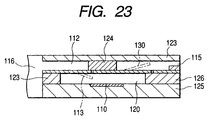
- a heat generating member 110 is disposed substantially in the middle of an ink flow path 112 between an ink tank 116 and a nozzle 115 on a substrate 125 for forming an inner wall of the ink flow path 112.
- the heat generating member 110 lies in a division 120 with an entirely closed periphery inside the ink flow path 112.
- the ink flow path 112 is constituted of the substrate 125, thin films 123, 126 directly laminated on the substrate 125, and ligulate pieces 113, 130 as closing members.
- the opened ligulate piece is shown by a broken line in Fig. 23.
- Another thin film 123 extending in a plane parallel to the substrate 125 and terminating in a stopper 124 shuts off on the ink flow path 112.
- a free end of the ligulate piece 130 in a nozzle area closely attached to the stopper 126 in a stationary state is displaced upward, and the ink liquid is discharged via the ink flow path 112 and nozzle 115 from the division 120.
- the ink liquid in the division 120 fails to go toward the ink layer 116.
- the ligulate piece 130 is displaced downward to again abut on the stopper 126.
- the ligulate piece 113 falls down in the ink division 120, and accordingly the ink liquid flows into the division 120.
- each of three chambers of the vicinity of the discharge port, bubble generator and ink supply section is divided into two, the ink following a liquid droplet trails long during discharge, and the number of satellite dots considerably increases as compared with an ordinary discharge system for performing bubble growth, shrinkage, and bubble vanishing (it is assumed that an effect of meniscus retreat by the bubble vanishing cannot be used).
- the valve on the side of the bubble discharge port causes much loss of discharge energy.
- an invention for enhancing an inhibition efficiency of a bubble growth component in a direction opposite to a discharge port and contrarily for enhancing a discharge efficiency based on a new idea to find out an inventive method for satisfying a highly efficient refill property and a head constitution.
- a function of a special check valve inhibits the bubble growth in a (rearward) direction opposite to a discharge port, and a rearward discharge energy can effectively be utilized on a discharge port side. Additionally, it has been found that the special check valve function inhibits a rearward bubble growth component, an efficient refill property is provided, and a discharge response frequency can therefore be set to be considerably high.
- an object of the present invention is to establish an inventive discharge system (structure) for simultaneously enhancing discharge power and discharge frequency by a nozzle structure and discharge method using an inventive valve function and for achieving a high speed, high image quality head of a level which has not been heretofore achieved.
- a liquid discharge head comprising: a plurality of discharge ports for discharging a liquid; a plurality of liquid flow paths whose one end always communicates with each of the discharge ports and which comprise a bubble generating area for generating a bubble in the liquid; bubble generating means for generating an energy to generate and grow the bubble; a plurality of liquid supply ports, disposed in the plurality of liquid flow paths, respectively, for communicating with a common liquid supply chamber; and a movable member having a free end supported at a slight gap with respect to the side of the liquid flow path of the liquid supply port.
- An area surrounded with at least a free end portion of the movable member and both side portions continued from the free end portion is larger than an opening area to the liquid flow path of the liquid supply port.
- a period when the movable member seals and substantially shuts off the opening area is provided from when a drive voltage is applied to the bubble generating means until a period of substantial isotropic growth of the entire bubble by the bubble generating means ends. After the period when the movable member seals and substantially shuts off the opening area, and while a portion of the bubble generated by the bubble generating means on the side of the discharge port grows, the movable member starts displacement on the side of the bubble generating means inside the liquid flow path, and liquid supply is enabled to the liquid flow path from the common liquid supply chamber.
- Vd a volume of a liquid droplet discharged from the discharge port
- Vm a drawing volume from the discharge port to a liquid surface retracted to maximum into the liquid flow path
- the slight gap between the movable member and the liquid supply port is preferably about 10 ⁇ m or less.
- a discharge direction of the liquid from the discharge port substantially crosses at right angles to a normal direction of a surface on which the bubble generating means is disposed, or the discharge port is supposedly disposed opposite to the bubble generating means.
- a liquid discharge apparatus comprising: the aforementioned liquid discharge head; and recording medium conveying means for conveying a recording medium to receive the liquid discharged from the liquid discharge head.
- recording medium conveying means for conveying a recording medium to receive the liquid discharged from the liquid discharge head.
- a liquid discharging method utilizing a liquid discharge head comprising:
- the liquid can satisfactorily be discharged by the rapid enhancement of the discharge power.
- the discharge power is rapidly enhanced, for example, by reducing a size of a heat generating member for use as bubble generating means, an energy to be projected for the discharge can be reduced.
- the movable member is displaced to the side of the bubble generating means with bubble shrinkage, the liquid rapidly flows into the liquid flow path via the liquid supply port from the common liquid supply chamber, and a flow for drawing a meniscus after the discharge into the liquid flow path from the discharge port rapidly decreases. Thereby, a retreat amount of meniscus in the discharge port after liquid droplet discharge decreases. As a result, after the discharge, the meniscus returns to its initial state in a very short time. Specifically, since a time for completing refilling of a constant amount of ink to the liquid flow path is short, even the discharge frequency (drive frequency) can rapidly be enhanced in performing a high-precision (constant-amount) ink discharge.
- upstream and downstream for use in the description of the present invention are represented with respect to a flow direction of the liquid toward the discharge port from a liquid supply source via the bubble generating area (or the movable member), or with respect to a constitutional direction.
- downstream side regarding the bubble itself means the bubble generated on a downstream side of the flow direction or the constitutional direction with respect to a bubble center, or in an area on the downstream side from an area center of the heat generating member.
- the movable member seals and substantially shuts off the liquid supply port in the present invention includes a case in which the movable member does not necessarily closely abut on the peripheral portion of the liquid supply port, and limitlessly approaches the liquid supply port.
- Fig. 1 is a sectional view along one liquid flow path direction of a liquid discharge head according to a first embodiment of the present invention
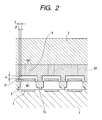
- Fig. 2 is a sectional view along an 2-2 line of Fig. 1
- Fig. 3 is a sectional view along a 3-3 line, shifted to the side of a top plate 2 at a point Y1 from a discharge port center of Fig. 1.
- an element substrate 1 is fixed to the top plate 2 via a liquid path side wall 10 in a laminated state, and a liquid flow path 3 whose one end communicates with a discharge port 7 is formed between both plates 1 and 2.
- a multiplicity of liquid flow paths 3 are disposed on one head.
- the element substrate 1 is provided with a heat generating member 4 of an electrothermal converting element or the like as bubble generating means for generating a bubble in a liquid with which the liquid flow path 3 is replenished.
- a bubble generating area 11 exists in which the heat generating member 4 is rapidly heated and bubbling occurs in the discharge liquid.
- Each of the multiplicity of liquid flow paths 3 is provided with a liquid supply port 5 formed by a supply section forming member 5A, and a common liquid supply chamber 6 is disposed to communicate with each liquid supply port 5.
- a configuration is branched to a multiplicity of liquid flow paths 3 from the single common liquid supply chamber 6, and an amount of the liquid adapted to the liquid discharged from the supply port 7 communicating with each liquid flow path 3 is received from the common liquid supply chamber 6.
- Character S of Fig. 1 denotes a substantial opening area to supply the liquid to the liquid flow path 3 of the liquid supply port.
- a movable member 8 is disposed with a slight gap ⁇ (e.g., 10 ⁇ m or less) and substantially parallel to the opening area S of the liquid supply port 5.
- An area surrounded with at least a free end portion of the movable member 8 and continued both side portions is larger than the opening area S of the liquid supply port 5 (see Fig. 3), and the side portion of the movable member 8 has a slight gap ⁇ from each of both flow path side walls 10 (see Figs. 2, 3).
- the aforementioned supply section forming member 5A has a gap ⁇ with respect to the movable member 8 as shown in Fig. 2.
- the gaps ⁇ , ⁇ differ with flow path pitches, but the movable member 8 easily shuts off the opening area S with a large gap ⁇ , and with a large gap ⁇ the movable member 8 more easily moves to the side of the element substrate 1 with bubble vanishing than in a stationary state in which the member is positioned via the gap ⁇ .
- the gap ⁇ is set to 1 ⁇ m
- gap ⁇ is 4 ⁇ m
- gap ⁇ is 5 ⁇ m.
- the movable member 8 has a width W1 larger than a width W2 of the opening area S in a width direction between the flow path side walls 10, and has a width such that the opening area S is sufficiently sealed.
- a portion 8B of the movable member 8 defines an upstream side end portion of the opening area S of the liquid supply port 5 on an extended line from the end portion on the side of a free end of a continuous portion by which a plurality of movable members are continued with respect to a direction crossing at right angles to a plurality of liquid paths (the continuous portion is partially apart from a fixing member 9 as shown in Fig. 1) (see Fig. 3).
- a portion of the supply section forming member 5A along the movable member 8 is set to be thinner than the liquid flow path side wall 10 itself, and the supply section forming member 5A is laminated with respect to the flow path wall 10.
- a thickness of the supply section forming member 5A on the side of the discharge port 7 from a free end 8A of the movable member is set to the same thickness as that of the liquid flow path wall 10 itself as shown in Fig. 3. Therefore, the movable member 8 can move in the liquid flow path 3 without any frictional resistance, and displacement toward the opening area S can be restricted in a peripheral portion of the opening area S. Thereby, the opening area S is substantially closed so that a liquid flow to the common liquid supply chamber 6 from the inside of the liquid flow path 3 can be prevented, while with bubble vanishing, movement is possible from a substantially sealed state to a refill possible state on the side of the liquid flow path. Moreover, in the present embodiment, the movable member 8 is also positioned parallel to the element substrate 1.
- the end 8B of the movable member 8 is a free end positioned on the side of the heat generating member 4 of the element substrate 1, and the other end is supported by the fixing member 9. Moreover, the fixing member 9 closes an end on the side of the liquid flow path 3 opposite to the discharge port 7.
- a "linear communication state" is obtained in which a linear flow path structure is kept with respect to the liquid flow.
- an ideal state is preferably formed in which a discharge direction, discharge speed and another discharge state of a discharge droplet are stabilized with a considerably high level.
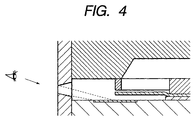
- the discharge port 7 may directly linearly be connected to the heat generating member 4, particularly the discharge port side (downstream side) of the heat generating member which exerts an influence on the bubble discharge port side in a constitution.
- This is a state with no fluid in the flow path, in which the heat generating member, particularly the downstream side of the heat generating member can be observed from the outside of the discharge port (see Fig. 4).
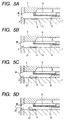
- FIGs. 5A to 5D and 6A to 6C are explanatory views of the discharge operation of the liquid discharge head with a structure shown in Figs. 1 to 3, showing the liquid discharge head in a view cut along a liquid flow path direction, and showing a characteristic phenomenon in divided processes of Figs. 5A to 5D and 6A to 6C.
- character M denotes a meniscus formed by the discharged liquid.
- Fig. 5A shows a state before an electric energy or another energy is applied to the heat generating member 4, and a state before the heat generating member generates heat.
- a slight gap (10 ⁇ m or less) exists between the movable member 8 disposed between the liquid supply port 5 and the liquid flow path 3, and a forming surface of the liquid supply port 5.
- Fig. 5B shows that a part of the liquid in the liquid flow path 3 is heated by the heat generating member 4, film boiling occurs on the heat generating member 4, and a bubble 21 isotropically grows.
- the bubble growth is isotropic means that a bubble growth speed directed in a perpendicular direction of a bubble surface has a substantially equal magnitude in any position of the bubble surface.
- the movable member 8 In the isotropic growth process of the bubble 21 in an initial stage of bubble generation, the movable member 8 closely abuts on the peripheral portion of the liquid supply port 5 to close the liquid supply port 5, and the inside of the liquid flow path 3 is substantially in a sealed state except the discharge port 7.
- This sealed state is maintained in any period in the isotropic growth process of the bubble 21. Additionally, the period for maintaining the sealed state may be between when a drive voltage is applied to the heat generating member 4 and when the isotropic growth process of the bubble 21 ends.
- inertance diffuseiculty in movement when a still liquid rapidly starts moving
- the inertance from the heat generating member 4 to the liquid supply port side in the liquid flow path 3 substantially becomes infinite. In this case, the inertance from the heat generating member 4 to the liquid supply port side approaches infinity when more distance is obtained between the heat generating member 4 and the movable member 8.
- Fig. 5C shows that the bubble 21 continues to grow.
- the liquid flow path 3 is substantially placed in the sealed state excluding the discharge port 7, no liquid flow goes to the liquid supply port 5 side. Therefore, among the bubbles isotropically grown on the heat generating member 4, the bubble on the liquid supply port 5 side cannot grow, and the bubble growth energy is consumed only in the bubble growth on the discharge port 7 side.
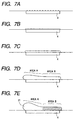
- Fig. 7A initial boiling occurs on the heat generating member when the heat generating member is heated, and subsequently as shown in Fig. 7B, the boiling changes to a film boiling in which the heat generating member is covered with the film-like bubble. Moreover, the bubble in a film boiling state continues to isotropically grow as shown in Figs. 7B and 7C (this isotropic bubble growth state is called a semi-pillow state). Additionally, when the inside of the liquid flow path 3 is substantially in the sealed state excluding the discharge port 7 as shown in Fig.
- an area in which no bubble grows on the heat generating member 4 is referred to as an area B, and an area on the side of the discharge port 7 in which the bubble grows is referred to as an area A. Additionally, a bubbling volume during the isotropic bubble growth is maximized in the area B.
- FIG. 7D shows that the bubble growth continues in the area A, and bubble shrinkage starts in the area B.
- the bubble largely grows toward the discharge port side in the area A.
- the bubble volume in the area B starts to decrease.
- the movable member 8 starts to be displaced downward to a stationary state position in accordance with its restoring force by rigidity and bubble vanishing force in the area B.
- the liquid supply port 5 opens, and the common liquid supply chamber 6 is placed in the communication state with the liquid flow path 3.
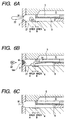
- Fig. 6A shows that the bubble 21 has grown substantially to maximum.
- the bubble grows to the maximum in the area A, and accordingly the bubble substantially vanishes in the area B.
- a discharge droplet 22 which is to be discharged from the discharge port 7 trails long and is still connected to the meniscus M.
- a maximum bubbling volume of the bubble is Vo.
- Fig. 6B shows that the bubble 21 stops growing and is in a stage only of a bubble vanishing process, and the discharge droplet 22 is cut from the meniscus M.
- a shrinkage energy of the bubble 21 acts as a force for moving the liquid in the vicinity of the discharge port 7 in an upstream direction as an entire balance. Therefore, the meniscus M is drawn into the liquid flow path 3 from the discharge port 7 at this point of time, and a liquid column connected to the discharge liquid droplet 22 is quickly cut off by a strong force.
- the movable member 8 is displaced downward with bubble shrinkage, and the liquid rapidly flows as a large flow into the liquid flow path 3 from the common liquid supply chamber 6 via the liquid supply port 5
- the retreat amount of the meniscus M decreases, and the meniscus M starts returning to the position before bubbling with a relatively low speed.
- a converging property of vibration of the meniscus M is very satisfactory as compared with the liquid discharge system which is not provided with the movable member of the present invention.
- a discharge amount is set to Vd
- a maximum meniscus retreat amount as a drawing volume from the discharge port to a liquid surface retracted to maximum into the liquid flow path is Vm
- an amount of the liquid moving into the liquid flow path 3 from when the free end of the movable member 8 starts its downward displacement until the retreat amount of the meniscus M is maximized is Vr.
- the retreat amount of the meniscus M is maximized when the vanishing of the bubble 21 ends, but the bubble 21 vanishes by the liquid flowing into the liquid flow path 3 from the common liquid supply chamber 6 via the liquid supply port 5 from the state shown in Fig. 6B until the bubble 21 vanishes, and the retreat amount of the meniscus M in the state shown in Fig. 6B can be said to be substantially a maximum meniscus retreat amount Vm.
- Fig. 6C shows that the bubble 21 completely vanishes, and the movable member 8 also returns to the stationary state position.
- the movable member 8 is displaced upward to this state by its elastic force (a direction of a solid-line arrow of Fig. 6B).
- the meniscus M already returns to the vicinity of the discharge port 7.
- the movable member 8 inhibits the liquid from flowing toward the liquid supply port 5 in a period when the bubble isotropically grows in the initial stage of bubble generation. Moreover, when the discharged liquid leaves the discharge port 7 to fly, the vanishing of the entire bubble already starts, the movable member 8 is displaced downward at this time, and the liquid flows into the liquid flow path 3 from the common liquid supply chamber 6 via the liquid supply port 5.
- the maximum meniscus retreat volume Vm becomes smaller than a volume attributed to the discharge amount Vd of the flying liquid.
- Figs. 25A-1 to 25A-7 are views of the liquid discharge head cut along the liquid flow path direction according to a modification of the present embodiment in which the relation of Vd > Vm is established
- Figs. 25B-1 to 25B-7 are views of the liquid discharge head cut along the liquid flow path direction according to a comparative mode in which a relation of Vd' > Vm' is established.
- the liquid discharge head according to the present modification is different from the liquid discharge head according to the comparative mode in positions of heat generating members 4, 4' .
- the liquid discharge head according to the present modification is driven on the same drive conditions as those of the liquid discharge head according to the comparative mode.
- the states of the liquid discharge heads shown in Figs. 25A-1 to 25A-7 and 25B-1 to 25B-7 substantially correspond to the states of the liquid discharge heads shown in Figs. 5A to 5D and 6A to 6C.
- the liquid discharge head according to the present modification becomes smaller than the liquid discharge head of the comparative mode in the maximum retreat amount of the meniscus. Therefore, in the liquid discharge head according to the present modification in which the relation of Vd > Vm is established, the meniscus M returns more quickly than in the liquid discharge head according to the comparative mode in which the relation of Vd' > Vm' is established. Therefore, the establishment of the relation of Vd > Vm means the quick returning of the meniscus M.
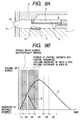
- Fig. 8 is a graph showing the correlation
- curve A shows the change of bubble volume with time in the area A
- curve B shows the change of bubble volume with time in the area B.
- the change of bubble growth volume with time in the area A draws a parabola having a maximum value.
- the bubble volume increases with an elapse of time from the start of bubbling until the bubble vanishing, reaches the maximum at a certain point of time, and subsequently decreases.
- time required from the start of bubbling until the bubble vanishing is short, the maximum growth volume of the bubble is small, and time until the growth volume reaches the maximum is also short.
- the area A is largely different from the area B in the time required from the bubbling start until the bubble vanishing and the bubble growth volume change, and those of the area B are smaller.
- the curve A is superposed on the curve B. Specifically, a period when the bubble isotropically grows (in the semi-pillow state) is generated in the initial stage of the bubble generation. Thereafter, the curve A draws a curve to increase to a maximum point, but the curve B is branched from the curve A at the certain point of time to draw a curve along which the bubble volume decreases. Specifically, a period when the bubble volume increases in the area A, but decreases in the area B (a period of partial growth and partial shrinkage) is generated.
- the movable member provides the following behavior. Specifically, the movable member is displaced upward toward the liquid supply port in a period (1) of Fig. 8. In a period (2) of Fig. 8 the movable member closely abuts on the liquid supply port, and the inside of the liquid flow path is substantially in the sealed state excluding the discharge port. The sealed state is started in the period when the bubble isotropically grows. Next in a period (3) of Fig. 8, the movable member is displaced downward toward the stationary state position.
- the opening of the liquid supply port by the movable member is started after a fixed time elapses after the start of the period of partial growth and partial shrinkage. Subsequently in a period (4) of Fig. 8, the movable member is further displaced downward from the stationary state. Next in a period (5) of Fig. 8, the downward displacement of the movable member substantially stops, and the movable member is in an equilibrium state in its opened position. Finally in a period (6) of Fig. 8, the movable member is displaced upward toward the stationary state position.
- the correlation between the bubble growth and the movable member behavior is influenced by the relative positions of the movable member and heat generating member.
- the correlation between the bubble growth and the movable member behavior in the liquid discharge head provided with the movable member and heat generating member in relative positions different from the positions in the present mode will next be described with reference to Figs. 9A, 9B, 10A and 10B.
- Fig. 9A and 9B are explanatory views of the correlation between the bubble growth and the movable member behavior in a mode in which the entire heat generating member is covered with the free end of the movable member
- Fig. 9A shows the mode
- Fig. 9B is a graph of the correlation.
- period (1) of Fig. 9B is short time as compared with the mode of Fig. 1, and more preferably the heat generating member is placed in the sealed state in a short time after being heated.
- the behaviors of the movable member in respective periods (1) to (6) of Fig. 9B are the same as the behaviors described with reference to Fig. 8.
- Fig. 9A since the movable member is easily influenced by the bubble volume decrease, as seen from a start point of period (3) of Fig. 9B, the opening of the liquid supply port by the movable member is started immediately after the start of the period of partial growth and partial shrinkage. Specifically, the opening timing of the movable member is fast as compared with the mode of Fig. 1. For similar reasons, an amplitude of movable member 8 is enlarged.
- Figs. 10A and 10B are explanatory views of the correlation between the bubble growth and the movable member behavior in a mode in which the heat generating member is apart from the movable member
- Fig. 10A shows the mode
- Fig. 10B is a graph of the correlation.
- the heat generating member is apart from the movable member as shown by the mode of Fig. 10A
- the movable member is not easily influenced by the bubble volume decrease, and as seen from the start point of period (3) of Fig. 10B, the opening of the liquid supply port by the movable member is started considerably later from the start of the period of partial growth and partial shrinkage.
- the opening timing of the movable member is slow as compared with the mode of Fig. 1.
- the amplitude of the movable member is reduced.
- the behaviors of the movable member in respective periods (1) to (6) of Fig. 10B are the same as the behaviors described with reference to Fig. 8.
- the head constitution and liquid discharge operation of the present embodiment have been described above, and according to the mode, growth components to downstream and upstream sides of the bubble are not uniform, most of the growth components toward the upstream side are eliminated and the movement of the liquid to the upstream side is inhibited. Since the liquid flow to the upstream side is inhibited, most of the bubble growth components on the upstream side are directed toward the discharge port without any loss, and discharge force is considerably enhanced. Furthermore, the retreat amount of meniscus after the discharge decreases, and accordingly an amount of the meniscus protruded from an orifice surface during refill also decreases. Therefore, meniscus vibration is inhibited and stable discharge can be performed in any drive frequency from a low frequency to a high frequency.
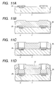
- FIG. 11A to 11D, 12A to 12C and 13A to 13C show the process by a surface cut along a direction crossing at right angles to the direction of the liquid flow path formed on the element substrate.
- an Al film is formed on a surface on the side of the heat generating member 4 of the element substrate 1 in a thickness of about 2 ⁇ m by a sputtering method.
- the formed Al film is patterned using a known photolithography process, and a plurality of Al film patterns 25 are formed in positions corresponding to the heat generating members 4.
- Each of the Al film patterns 25 is extended to an area in which an SiN film 26 as a material film for partially forming the support member 9 and flow path side wall 10 is etched in a process of Fig. 11C described later.
- the Al film pattern 25 functions as an etching stop layer during formation of the liquid flow path 3 by dry etching as described later. This is because a TiW layer as a pad protective layer in the element substrate 1, Ta film as a cavitation-resistant film, and SiN film as a protective layer on a resistor are etched by etching gas for use in forming the liquid flow path 3, and the etching of these layers or films is prevented by the Al film pattern 25.
- a width along a direction crossing at right angles to the flow path direction of the liquid flow path 3 in the Al film pattern 25 is set to be larger than the width of the finally formed liquid flow path 3 so that the surface of the element substrate 1 on the side of the heat generating member 4, or the TiW layer on the element substrate 1 is prevented from being exposed during the formation of the liquid flow path 3 by dry etching.
- ionic species and radicals are generated by decomposition of CF 4 , C X F Y , SF 6 gas, and the heat generating member 4 and function element of the element substrate 1 are damaged in some cases, but the Al film pattern 25 receives these ionic species and radicals to protect the heat generating member 4 and function element of the element substrate 1.
- the SiN film 26 with a thickness of about 20.0 ⁇ m as the material film for forming a part of the flow path side wall 10 is formed using a plasma CVD method on the surface of the Al film pattern 25 and the surface of the element substrate 1 on the side of the Al film pattern 25 to cover the Al film pattern 25.
- the Al film (not shown) is formed on a portion of the surface of the SiN film 26 excluding the portion for forming the liquid flow path 3.
- an etching apparatus using a dielectric bonding plasma to etch the SiN film 26 a part of the flow path side wall 10 is formed.
- the SiN film 26 is etched.
- Constituting materials of a close abutment portion of the support member 9 of movable member 8 and the element substrate 1 include TiW as the constituting material of a pad protective layer, and Ta as the constituting material of the cavitation-resistant film of the element substrate 1.
- an Al film 27 with a thickness of 20.0 ⁇ m is formed on the surface of the SiN film 26 by the sputtering method, and a hole formed by etching the SiN film 26 as the portion for forming the liquid flow path 3 in a preprocess is filled with Al.
- Fig. 12A the surfaces of the SiN film 26 and Al film 27 on the substrate 1 shown in Fig. 11D are flatly polished by chemical mechanical polishing (CMP).
- CMP chemical mechanical polishing
- the formed Al film 28 is patterned using the known photolithography process.
- the pattern of the Al film 28 is extended to an area in which an SiN film 29 as the material film for forming a base portion (or fixing portion) to form a bond portion of the movable member 8 and support member is etched in a process of Fig. 12C described later.
- the Al film 28 functions as the etching stop layer during formation of the movable member 8 by dry etching as described later.
- the SiN film 26 as a part of the liquid flow path 3 is prevented from being etched by the etching gas for use in forming the movable member 8.
- an SiN film with a thickness of about 3.0 ⁇ m as the material film for forming the movable member 8 is formed on the surface of the Al film 28 using the plasma CVD method.
- the formed SiN film is dry-etched using the etching apparatus using the dielectric bonding plasma to leave the SiN film 29 in a place corresponding to the Al film 28 as a part of the liquid flow path 3.
- the method by the etching apparatus is similar to that of the process of Fig. 11C. Since the SiN film 29 finally forms the movable member 8, the width along the direction crossing at right angles to the flow path direction of the liquid flow path 3 in the pattern of the SiN film 29 is smaller than the width of the finally formed liquid flow path 3.
- an Al film with a thickness of 3.0 ⁇ m as the material film for forming a gap forming member 30 is formed on the surface of the Al film 28 by the sputtering method to cover the SiN film 29.
- the gap forming member 30 for forming the gap ⁇ between the top surface of movable member 8 and the liquid supply port 5 and the gap ⁇ between the side portion of movable member 8 and the flow path side wall 10 shown in Fig. 2 is formed on the surface and side surface of the SiN film 29.
- a negative photosensitive epoxy resin 31 consisting of a material shown in the following Table 1 is applied with a thickness of 30.0 ⁇ m on the substrate including the gap forming member 30 of the Al film by spin coating. Additionally, in the aforementioned spin coating process, the epoxy resin 31 as a part of the flow path side wall 10 to which the top plate 2 is bonded can flatly be applied.
- Fig. 13C mixture acid of acetic acid, phosphoric acid and nitric acid is used to heat/etch the Al films 25, 27, 28 and 30, these films are eluted and removed, and the liquid supply port 5, movable member 8, support member 9 and flow path side wall 10 are formed on the element substrate 1. Thereafter, hydrogen peroxide is used to remove portions corresponding to the heat generating member (bubble generating means) 4 and pad from the TiW film as the pad protective layer formed on the element substrate 1.
- the close abutment portion of the element substrate 1 and flow path side wall 10 also includes TiW as the constituting material of the pad protective layer, and Ta as the constituting material of the cavitation-resistant film of the element substrate 1.
- the liquid discharge head was prepared as shown in Figs. 1 to 3.
- the element substrate 1 is bonded to the top plate 2, and the liquid flow path 3 whose one end communicates with the discharge port 7 is formed between both plates 1 and 2.
- liquid supply port 5 Disposed in the liquid flow path 3 are the liquid supply port 5 and the common liquid supply chamber 6 which communicates with the liquid supply port 5.
- the movable member 8 is disposed substantially parallel to the opening area of the liquid supply port 5 with the slight gap ⁇ (e.g., 10 ⁇ m or less).
- the area surrounded with at least the free end portion of the movable member 8 and continued both side portions is larger than the opening area S to the liquid flow path of the liquid supply port 5, and the side portion of the movable member 8 has the slight gap ⁇ from the liquid flow path side wall 10.
- the movable member 8 is disposed opposite to the element substrate 1. Furthermore, one end of the movable member 8 is a free end displaced on the side of the heat generating member 4 of the element substrate 1, and the other end is supported by the support member 9.
- the manufacture process for disposing the movable member 8, flow path side wall 10 and liquid supply port 5 on the element substrate 1 has been described, but this is not limited, and a process of bonding the top plate 2 with the movable member 8 and liquid supply port 5 formed thereon beforehand to the element substrate 1 with the flow path side wall 10 formed thereon may be used.
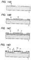
- Figs. 14A to 14D, 15A, 15B and 16 show the process by a surface cut along the direction crossing at right angles to the direction of the liquid flow path formed on the element substrate.
- Fig. 16 shows a sectional view of a schematic constitution of the liquid discharge head using the top plate prepared in Figs. 14A to 14D, 15A and 15B. Moreover, in the description, the same reference numerals are used for the same constituting elements as those of the first embodiment.
- an oxide film (SiO 2 ) 35 is formed in about 1.0 ⁇ m on one surface of the top plate 2 consisting of an Si material. Subsequently, the formed SiO 2 film 35 is patterned using the known photolithography process to remove the SiO 2 film corresponding to the forming place of the liquid supply port 5 shown in Fig. 16.
- a gap forming member 36 consisting of the Al film is applied in about 3.0 ⁇ m to cover the removed portion of the SiO 2 film 35 in one surface of the top plate 2 and the peripheral portion.
- the gap forming member 36 is used to form the gap between the liquid supply port 5 and the movable member 8 formed in a process of Fig. 15B described later.
- an SiN film 37 with a thickness of about 3.0 ⁇ m as the material film for forming the movable member 8 is formed to cover the gap forming member 36.
- the known photolithography process is used to pattern the movable member 8.
- the gap forming member is used as the etching stop layer to perform through etching on the Si top plate (thickness of 625 ⁇ m), and the common liquid supply chamber is formed.
- mixture acid of acetic acid, phosphoric acid and nitric acid is used to heat/etch the Al film as the gap forming member 36, and the film is eluted and removed.
- 2 ⁇ m or more gap ⁇ is disposed between a movable portion 37a to form the movable member 8 and a support portion 37b in the SiN film 37.
- a plurality of slits 37c passed through the surface and back surface are formed preferably in 1 ⁇ m or less.
- a projection area of the movable portion 37a is larger than the opening area (the removed area of the SiO 2 film 35) which forms the liquid supply port.
- the removed portion of the SiO 2 film 35 is subjected to anisotropic wet etching via the slit 37c of the movable portion 37a, and the liquid supply port 5 is formed.
- the LPCVD method is used to form an SiN film 38 with a thickness of about 0.5 ⁇ m, and the slit 37c opened in the movable member 8 is filled with the SiN film 38.
- the gap of the slit 37C is set to 1 ⁇ m or less, the slit 37c is closed, but the gap ⁇ between the movable portion 37a and the support portion 37b is set to 2 ⁇ m or more and the gap ⁇ therefore fails to be closed by the SiN film 38.
- the silicon side wall formed by the anisotropic etching or the through etching of the silicon top plate is also coated with the SiN film by the LPCVD method, and corrosion by the ink is prevented.
- the liquid discharge head shown in Fig. 16 was prepared. Even the liquid discharge head of this mode provides the similar effect to that of the liquid discharge head of the structure shown in Figs. 1 to 3.
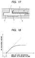
- Fig. 17 is a sectional view of the liquid discharge head of a so-called side shooter type according to a third embodiment of the present invention.
- the liquid discharge head of this mode is different from the first embodiment in that the heat generating member 4 faces the discharge port 7 on a parallel plane as shown in Fig. 17, and the liquid flow path 3 communicates at right angles with an axial direction along a discharge direction of the liquid from the discharge port 7. Even in this liquid discharge head, the effect is provided based on a discharge principle similar to that of the first embodiment, and the manufacture method described in the first and second embodiments can easily be applied.
- the material constituting the movable member is not limited as long as the material is provided with resistance to a solvent with respect to the discharge liquid, and with elasticity to satisfactorily operate as the movable member.
- Examples of the material of the movable member preferably include: metals such as silver, nickel, gold, iron, titanium, aluminum, platinum, tantalum, stainless, and phosphor bronze and alloys of the metals; or resins with nitrile groups such as acrylonitrile, butadiene, and styrene, resins with amide groups such as polyamide, resins with carboxyl groups such as polycarbonate, resins with aldehyde groups such as polyacetal, resins with sulfone groups such as polysulfone, other resins such as liquid crystal polymer and compounds of the resins, highly ink-resistant metals such as gold, tungsten, tantalum, nickel, stainless and titanium, alloys of these metals and materials whose surfaces are coated with respect to resistance to ink; or resins with amide groups such as polyamide, resins with aldehyde groups such as polyacetal, resins with ketone groups such as polyether ether ketone, resins with imide groups such as polyimide
- a so-called bubble jet recording method as shown by a broken line of Fig. 18, a heat generating member area is in a proportional relation with an ink discharge amount, but it is seen that there exists a non-bubbling effective area S which does not contribute to the ink discharge. Moreover, it is seen from a scorch state on the heat generating member that the non-bubbling effective area S exists around the heat generating member.
- the liquid flow path including the bubble generating means is substantially shielded excluding the discharge port so that the maximum discharge amount is regulated, as shown by a solid line of Fig. 18, there is an area in which the discharge amount fails to change even with large dispersions of the heat generating member area and bubbling volume, and the discharge amount of large dots can be stabilized by utilizing the area.
- a distance between the movable member and the heat generating member in a standby state is preferably set to 10 ⁇ m or less.
- a constitution of the element substrate 1 provided with the heat generating member 4 for applying heat to the liquid will be described hereinafter.
- Figs. 19A and 19B show side sectional views of a main part of a liquid discharge apparatus of the present invention
- Fig. 19A shows the head with a protective film described later
- Fig. 19B shows the head without the protective film.
- the top plate 2 is disposed on the element substrate 1, and the liquid flow path 3 is formed between the element substrate 1 and the top plate 2.
- a silicon oxide film or a silicon nitride film 106 for purposes of insulation and heat storage is formed on a substrate 107 of silicon or the like, and on the film an electric resistance layer 105 (thickness of 0.01 to 0.2 ⁇ m) of hafnium boride (HfB 2 ), tantalum nitride (TaN), tantalum aluminum (TaAl) or the like and a wiring electrode 104 (thickness of 0.2 to 1.0 ⁇ m) of aluminum or the like are patterned to constitute the heat generating member 4 as shown in Fig. 19A.
- HfB 2 hafnium boride
- TaN tantalum nitride
- TaAl tantalum aluminum
- a wiring electrode 104 thickness of 0.2 to 1.0 ⁇ m
- a protective film 103 of silicon oxide, silicon nitride or the like is formed with a thickness of 0.1 to 2.0 ⁇ m on the resistance layer 105 between the wiring electrodes 104, and further on the film a cavitation-resistant layer 102 of tantalum or the like (thickness of 0.1 to 0.6 ⁇ m) is formed, so that the resistance layer 105 is protected from various liquids such as the ink.
- the aforementioned resistance layer 105 may require no protective film 103 by combination of the liquid, flow path constitution, and resistance material, and an example of such constitution is shown in Fig. 19B.
- As the material of the resistance layer 105 which requires no protective film 103 iridium-tantalum-aluminum alloy, and the like are exemplified.
- the heat generating member 4 in the aforementioned respective embodiments may be constituted only of the resistance layer 105 (heat generator) between the electrodes 104, or may include the protective film 103 to protect the resistance layer 105.
- the heat generator constituted of the resistance layer 105 which generates heat in response to an electric signal is used as the heat generating member 4, but this is not limited, and the constitution may generate the bubble sufficient for discharging the discharge liquid in a bubbling liquid.
- the heat generating member may comprise a photothermal converting element which receives laser or another light to generate the heat or a heat generator which receives a high frequency to generate the heat.
- the function elements such as the transistor, diode, latch, and shift register for selectively driving the heat generating member 4 (electrothermal converting element) may integrally be formed by a semiconductor manufacture process.
- the resistance layer 105 between the wiring electrodes 104 is steeply allowed to generate the heat.
- drive signal conditions are not limited to these, and a drive signal which can adequately bubble the bubbling liquid may be used.
- the ink of the composition used in a conventional bubble jet apparatus can be used as the liquid for use in recording (recording liquid).
- the discharge liquid itself desirably fails to inhibit the discharge, the bubbling, the operation of the movable member, or the like.
- a highly viscous ink or the like can be utilized as the recording discharge liquid.
- the ink of the following composition is used as the recording liquid which can be used in the discharge liquid and the recording is performed, but the ink discharge speed is raised by enhancement of the discharge force, and therefore reaching precision of liquid droplet is enhanced so that a very satisfactory recorded image can be obtained.
- Dye ink viscosity 2 cP C.I. food black 2
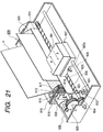
- FIG. 21 schematically shows a constitution of an ink jet recording apparatus as one example of a liquid discharge apparatus on which the liquid discharge head of the structure described in the first to third embodiments can be mounted and applied.
- a head cartridge 601 mounted on an ink jet recording apparatus 600 shown in Fig. 21 includes the liquid discharge head of the aforementioned structure, and a liquid container for holding the liquid supplied to the liquid discharge head.
- the head cartridge 601 is mounted on a carriage 607 which meshes with a helical groove 606 of a lead screw 605 rotating via drive force transmission gears 603 and 604 in cooperation with forward/backward rotation of a driving motor 602.
- the ink jet recording apparatus 600 is provided with recording medium conveying means (not shown) for conveying a printing sheet P as the recording medium which receives the ink or another liquid discharged from the head cartridge 601.
- recording medium conveying means (not shown) for conveying a printing sheet P as the recording medium which receives the ink or another liquid discharged from the head cartridge 601.
- Photocouplers 611 and 612 are disposed in the vicinity of one end of the lead screw 605.
- the photocouplers 611 and 612 are home position detecting means for confirming the presence of a lever 607a of the carriage 607 in an area of the photocouplers 611 and 612 to switch a rotation direction of the driving motor 602.
- Disposed in the vicinity of one end of the platen 609 is a support member 613 for supporting a cap member 614 which covers a front surface provided with a discharge port of the head cartridge 601.
- ink suction means 615 is disposed which sucks the ink stored inside the cap member 614 by empty discharge from the head cartridge 601. Suction recovery of the head cartridge 601 is performed via an opening of the cap member 614 by the ink suction means 615.
- the ink jet recording apparatus 600 is provided with a main body support member 619.
- the main body support member 619 supports a moving member 618 so that the member can move in a forward/backward direction, that is, a direction extended at right angles to the moving direction of the carriage 607.
- a cleaning blade 617 is attached to the moving member 618.
- the cleaning blade 617 is not limited to this mode, and a known cleaning blade of another mode may be used.
- a lever 620 for starting the suction in a suction recovery operation by the ink suction means 615 is disposed, the lever 620 moves with movement of a cam 621 which meshes with the carriage 607, and a drive force from the driving motor 602 is controlled for the movement by known transmission means such as clutch switching.
- An ink jet recording controller for applying a signal to the heat generating member mounted on the head cartridge 601 or performing drive control of the aforementioned respective mechanisms is disposed on a recording apparatus main body side, and this is not shown in Fig. 21.
- the head cartridge 601 reciprocates/moves over the entire width of the printing sheet P with respect to the printing sheet P conveyed on the platen 609 by the recording medium conveying means.
- the drive signal is supplied to the head cartridge 601 from drive signal supply means (not shown) during the movement, in response to the signal the liquid discharge head portion discharges the ink (recording liquid) to the recording medium, and recording is performed.
- Fig. 22 is a block diagram of the entire recording apparatus for performing ink jet recording by the liquid discharge apparatus of the present invention.
- the recording apparatus receives printing information as a control signal from a host computer 300.
- the printing information is temporarily stored in an input interface 301 inside a printing apparatus, converted to data which can be processed in the recording apparatus, and inputted to a central processing unit (CPU) 302 which also serves as head drive signal supply means.
- the CPU 302 uses peripheral units such as a random access memory (RAM) 304 to process the data inputted to the CPU 302 based on a control program stored in a read only memory (ROM) 303, and converts the data to data to be printed (image data).
- RAM random access memory
- ROM read only memory
- the CPU 302 prepares drive data for driving the driving motor 602 to move the recording sheet and the carriage 607 with the head cartridge 601 mounted thereon in synchronization with the image data.
- the image data and the motor drive data are transmitted to the head cartridge 601 and the driving motor 602 via a head driver 307 and a motor driver 305, respectively, and the motor is driven at a controlled timing to form an image.
- various papers or OHP sheets plastic materials for use in a compact disk, decorating plate, and the like, cloth, metal materials such as aluminum and copper, leathers such as ox/cow hide, pigskin and artificial leather, wood materials such as wood and plywood, bamboo materials, ceramic materials such as tiles, three-dimensional structure materials such as sponge, and the like can be used.
- the recording apparatus includes a printer apparatus for performing recording on various papers, OHP sheets, and the like, a plastic recording apparatus for performing recording on the plastic materials such as the compact disk, a metal recording apparatus for performing recording on a metal plate, a leather recording apparatus for performing recording on the leather, a wood material recording apparatus for performing recording on the wood material, a ceramic recording apparatus for performing recording on the ceramic material, a recording apparatus for performing recording on the three-dimensional net structure materials such as the sponge, a textile printing apparatus for performing recording on the cloth, and the like.
- a printer apparatus for performing recording on various papers, OHP sheets, and the like a plastic recording apparatus for performing recording on the plastic materials such as the compact disk, a metal recording apparatus for performing recording on a metal plate, a leather recording apparatus for performing recording on the leather, a wood material recording apparatus for performing recording on the wood material, a ceramic recording apparatus for performing recording on the ceramic material, a recording apparatus for performing recording on the three-dimensional net structure materials such as the sponge, a textile printing apparatus for performing recording on the cloth, and
- the communication state between the liquid flow path and the liquid supply port is immediately shut off by the movable member, and the inside of the liquid flow path is substantially placed in the sealed state excluding the discharge port, and most of the pressure wave by the bubble growth in the bubble generating area is directed to the discharge port side without being propagated to the liquid supply port or the common liquid supply chamber, so that the discharge power can rapidly be enhanced.
- the highly viscous ink can satisfactorily be discharged by rapid enhancement of the discharge power.
- the ink thickening area increases in the discharge port with the environmental change during recording, particularly under an environment with low temperature and low humidity, and the ink is not normally discharged at the start of use, but in the present invention the ink can satisfactorily be discharged from first.
- the discharge power is rapidly enhanced, it is possible to reduce the size of the heat generating member for use as the bubble generating means and to reduce the energy to be projected for the discharge.
- a liquid discharge head comprising: a plurality of discharge ports for discharging a liquid; a plurality of liquid flow paths whose one end portion always communicates with each of the discharge ports and which comprise a bubble generating area for generating a bubble in the liquid; bubble generating means for generating an energy to generate and grow the bubble; a plurality of liquid supply ports, disposed in the liquid flow paths, for communicating with a common liquid supply chamber; and a movable member having a free end supported at a slight gap with respect to the liquid flow path of the liquid supply port, so that recording of a high quality level image is achieved at a high speed.
- Vd a volume of a liquid droplet discharged from the discharge port
- Vm a drawing volume from the discharge port to a liquid surface retracted to maximum into the liquid flow path
Applications Claiming Priority (2)
| Application Number | Priority Date | Filing Date | Title |
|---|---|---|---|
| JP25093699 | 1999-09-03 | ||
| JP25093699 | 1999-09-03 |
Publications (2)
| Publication Number | Publication Date |
|---|---|
| EP1080902A1 true EP1080902A1 (de) | 2001-03-07 |
| EP1080902B1 EP1080902B1 (de) | 2004-12-29 |
Family
ID=17215228
Family Applications (1)
| Application Number | Title | Priority Date | Filing Date |
|---|---|---|---|
| EP00119059A Expired - Lifetime EP1080902B1 (de) | 1999-09-03 | 2000-09-01 | Flüssigkeitsausstosskopf, Flüssigkeitsausstossapparat und Flüssigkeitsausstossverfahren |
Country Status (4)
| Country | Link |
|---|---|
| US (1) | US6533400B1 (de) |
| EP (1) | EP1080902B1 (de) |
| AT (1) | ATE285898T1 (de) |
| DE (1) | DE60017032T2 (de) |
Cited By (1)
| Publication number | Priority date | Publication date | Assignee | Title |
|---|---|---|---|---|
| EP1083049A3 (de) * | 1999-09-03 | 2002-08-07 | Canon Kabushiki Kaisha | Flüssigkeitsausstosskopf, Flüsigkeitsausstossvorrichtung und Verfahren zur Herstellung eines Flüssigkeitsausstosskopfes |
Families Citing this family (11)
| Publication number | Priority date | Publication date | Assignee | Title |
|---|---|---|---|---|
| JP2003025577A (ja) * | 2001-07-11 | 2003-01-29 | Canon Inc | 液体吐出ヘッド |
| JP4095368B2 (ja) * | 2001-08-10 | 2008-06-04 | キヤノン株式会社 | インクジェット記録ヘッドの作成方法 |
| GB2386434A (en) * | 2002-03-13 | 2003-09-17 | Univ Southampton | Microstructured optical fibre fabricated by extrusion through special extruder die |
| JP3970226B2 (ja) * | 2002-09-10 | 2007-09-05 | キヤノン株式会社 | 液体微細搬送装置 |
| CN1968815B (zh) * | 2004-06-28 | 2013-05-01 | 佳能株式会社 | 排液头制造方法,和使用该方法得到的排液头 |
| JP4459037B2 (ja) * | 2004-12-01 | 2010-04-28 | キヤノン株式会社 | 液体吐出ヘッド |
| JP4221611B2 (ja) * | 2006-10-31 | 2009-02-12 | セイコーエプソン株式会社 | 液体噴射ヘッドの製造方法 |
| JP2009119650A (ja) * | 2007-11-13 | 2009-06-04 | Canon Inc | インクジェットヘッドの製造方法 |
| US20090136875A1 (en) * | 2007-11-15 | 2009-05-28 | Canon Kabushiki Kaisha | Manufacturing method of liquid ejection head |
| JP2009220286A (ja) * | 2008-03-13 | 2009-10-01 | Canon Inc | 液体吐出記録ヘッド及その製造方法 |
| US8956325B2 (en) * | 2011-12-07 | 2015-02-17 | Stmicroelectronics, Inc. | Piezoelectric microfluidic pumping device and method for using the same |
Citations (4)
| Publication number | Priority date | Publication date | Assignee | Title |
|---|---|---|---|---|
| EP0764528A2 (de) * | 1995-09-22 | 1997-03-26 | Canon Kabushiki Kaisha | Verfahren zum Ausstossen von Flüssigkeit, Flüssigkeitsausstosskopf, Vorrichtung zum Ausstossen von Flüssigkeit, Flüssigkeitsbehälter und Kopfkassette |
| EP0816088A1 (de) * | 1996-07-02 | 1998-01-07 | Hewlett-Packard Company | Flüssigkeitsmikroventil zum Modulieren eines Flüssigkeitsstromes in einem Tintenstrahldrucker |
| US5897789A (en) * | 1995-10-26 | 1999-04-27 | Hewlett-Packard Company | Valve assembly for controlling fluid flow within an ink-jet pen |
| EP0976562A2 (de) * | 1998-07-28 | 2000-02-02 | Canon Kabushiki Kaisha | Flüssigkeitsausstosskopf und Flüssigkeitsausstossverfahren |
Family Cites Families (44)
| Publication number | Priority date | Publication date | Assignee | Title |
|---|---|---|---|---|
| CA1127227A (en) | 1977-10-03 | 1982-07-06 | Ichiro Endo | Liquid jet recording process and apparatus therefor |
| JPS5581172A (en) | 1978-12-14 | 1980-06-18 | Canon Inc | Liquid injection type recording method and device |
| US4417251A (en) | 1980-03-06 | 1983-11-22 | Canon Kabushiki Kaisha | Ink jet head |
| JPS57102366A (en) | 1980-12-18 | 1982-06-25 | Canon Inc | Ink jet head |
| US4450455A (en) | 1981-06-18 | 1984-05-22 | Canon Kabushiki Kaisha | Ink jet head |
| US4437100A (en) | 1981-06-18 | 1984-03-13 | Canon Kabushiki Kaisha | Ink-jet head and method for production thereof |
| US4558333A (en) | 1981-07-09 | 1985-12-10 | Canon Kabushiki Kaisha | Liquid jet recording head |
| US4611219A (en) | 1981-12-29 | 1986-09-09 | Canon Kabushiki Kaisha | Liquid-jetting head |
| JPS58220754A (ja) | 1982-06-18 | 1983-12-22 | Canon Inc | インクジエツト記録ヘツド |
| JPS58220756A (ja) | 1982-06-18 | 1983-12-22 | Canon Inc | インクジエツト記録ヘツドの製造方法 |
| US4609427A (en) | 1982-06-25 | 1986-09-02 | Canon Kabushiki Kaisha | Method for producing ink jet recording head |
| JPS5919168A (ja) | 1982-07-26 | 1984-01-31 | Canon Inc | インクジエツト記録ヘツド |
| US4480259A (en) | 1982-07-30 | 1984-10-30 | Hewlett-Packard Company | Ink jet printer with bubble driven flexible membrane |
| US4496960A (en) | 1982-09-20 | 1985-01-29 | Xerox Corporation | Ink jet ejector utilizing check valves to prevent air ingestion |
| JPS59123672A (ja) | 1982-12-28 | 1984-07-17 | Canon Inc | 液体噴射ヘッド及び液体噴射記録装置 |
| US4646110A (en) | 1982-12-29 | 1987-02-24 | Canon Kabushiki Kaisha | Liquid injection recording apparatus |
| JPS60222672A (ja) | 1984-04-18 | 1985-11-07 | Nec Corp | 弁素子 |
| JPS61110557A (ja) | 1984-11-05 | 1986-05-28 | Canon Inc | 液体噴射記録ヘツド |
| JPS6169467A (ja) | 1985-06-11 | 1986-04-10 | Seiko Epson Corp | 記録液滴吐出型記録装置 |
| JPS62156969A (ja) | 1985-12-28 | 1987-07-11 | Canon Inc | 液体噴射記録ヘツド |
| JPS6328654A (ja) | 1986-07-23 | 1988-02-06 | Nec Corp | インクジエツトヘツドのインク整流機構 |
| JPS63197652A (ja) | 1987-02-13 | 1988-08-16 | Canon Inc | インクジエツト記録ヘツドおよびその製造方法 |
| JPS63199972A (ja) | 1987-02-13 | 1988-08-18 | Canon Inc | 弁素子の製造方法 |
| US4994825A (en) | 1988-06-30 | 1991-02-19 | Canon Kabushiki Kaisha | Ink jet recording head equipped with a discharging opening forming member including a protruding portion and a recessed portion |
| US5208604A (en) | 1988-10-31 | 1993-05-04 | Canon Kabushiki Kaisha | Ink jet head and manufacturing method thereof, and ink jet apparatus with ink jet head |
| DE68927716T2 (de) | 1988-10-31 | 1997-05-28 | Canon Kk | Flüssigkeitsstrahlaufzeichnungskopf und mit diesem Kopf ausgerüstetes Gerät |
| JP2883113B2 (ja) | 1989-08-24 | 1999-04-19 | 富士ゼロックス株式会社 | インクジェットプリントヘッド |
| DE69025958T2 (de) | 1989-09-18 | 1996-11-14 | Canon Kk | Tintenstrahlaufzeichnungskopf und Tintenstrahlgerät mit diesem Kopf |
| ATE200250T1 (de) | 1989-09-18 | 2001-04-15 | Canon Kk | Tintenstrahlgerät |
| CA2025561C (en) | 1989-09-18 | 1995-07-11 | Seiichiro Karita | Recording head with cover |
| EP0436047A1 (de) | 1990-01-02 | 1991-07-10 | Siemens Aktiengesellschaft | Flüssigkeitsstrahlaufzeichnungskopf für Tintendruckeinrichtungen |
| JPH03240546A (ja) | 1990-02-19 | 1991-10-25 | Silk Giken Kk | インクジェット式印字ヘッド |
| JP2889342B2 (ja) | 1990-09-08 | 1999-05-10 | 富士ゼロックス株式会社 | サーマルインクジェットヘッド |
| JPH05124189A (ja) | 1991-11-01 | 1993-05-21 | Matsushita Electric Ind Co Ltd | インク吐出装置 |
| JPH05229122A (ja) | 1992-02-25 | 1993-09-07 | Seiko Instr Inc | インクジェットプリントヘッドおよびインクジェットプリントヘッドの駆動方法 |
| US5278585A (en) | 1992-05-28 | 1994-01-11 | Xerox Corporation | Ink jet printhead with ink flow directing valves |
| JPH0687214A (ja) | 1992-09-04 | 1994-03-29 | Sony Corp | インクジェットプリントヘッドとインクジェットプリンタ及びその駆動方法 |
| JPH06126964A (ja) | 1992-10-16 | 1994-05-10 | Canon Inc | インクジェットヘッドおよび該インクジェットヘッドを備えたインクジェット記録装置 |
| SG52140A1 (en) | 1994-03-04 | 1998-09-28 | Canon Kk | Ink jet recording head and method of manufacture therefor and laser processing apparatus and ink jet recording apparatus |
| DE69529586T2 (de) | 1994-05-27 | 2003-11-20 | Canon Kk | Tintenstrahlkopf, Tintenstrahlgerät und Verfahren zur Füllen einer Puffenkammer mit Blasen |
| EP0737582B1 (de) | 1995-04-14 | 2002-07-10 | Canon Kabushiki Kaisha | Verfahren zum Herstellen eines Flüssigkeitsausstosskopfes und nach diesem Verfahren hergestellter Flüssigkeitsausstosskopf |
| CN1072115C (zh) | 1995-04-26 | 2001-10-03 | 佳能株式会社 | 液体喷头 |
| US5821962A (en) * | 1995-06-02 | 1998-10-13 | Canon Kabushiki Kaisha | Liquid ejection apparatus and method |
| JPH09141873A (ja) | 1995-09-22 | 1997-06-03 | Canon Inc | 液体吐出ヘッド、液体吐出装置、および記録方法 |
-
2000
- 2000-08-31 US US09/652,664 patent/US6533400B1/en not_active Expired - Fee Related
- 2000-09-01 AT AT00119059T patent/ATE285898T1/de not_active IP Right Cessation
- 2000-09-01 DE DE60017032T patent/DE60017032T2/de not_active Expired - Lifetime
- 2000-09-01 EP EP00119059A patent/EP1080902B1/de not_active Expired - Lifetime
Patent Citations (4)
| Publication number | Priority date | Publication date | Assignee | Title |
|---|---|---|---|---|
| EP0764528A2 (de) * | 1995-09-22 | 1997-03-26 | Canon Kabushiki Kaisha | Verfahren zum Ausstossen von Flüssigkeit, Flüssigkeitsausstosskopf, Vorrichtung zum Ausstossen von Flüssigkeit, Flüssigkeitsbehälter und Kopfkassette |
| US5897789A (en) * | 1995-10-26 | 1999-04-27 | Hewlett-Packard Company | Valve assembly for controlling fluid flow within an ink-jet pen |
| EP0816088A1 (de) * | 1996-07-02 | 1998-01-07 | Hewlett-Packard Company | Flüssigkeitsmikroventil zum Modulieren eines Flüssigkeitsstromes in einem Tintenstrahldrucker |
| EP0976562A2 (de) * | 1998-07-28 | 2000-02-02 | Canon Kabushiki Kaisha | Flüssigkeitsausstosskopf und Flüssigkeitsausstossverfahren |
Cited By (4)
| Publication number | Priority date | Publication date | Assignee | Title |
|---|---|---|---|---|
| EP1083049A3 (de) * | 1999-09-03 | 2002-08-07 | Canon Kabushiki Kaisha | Flüssigkeitsausstosskopf, Flüsigkeitsausstossvorrichtung und Verfahren zur Herstellung eines Flüssigkeitsausstosskopfes |
| US6497475B1 (en) | 1999-09-03 | 2002-12-24 | Canon Kabushiki Kaisha | Liquid discharge method, head, and apparatus which suppress bubble growth at the upstream side |
| US6854831B2 (en) | 1999-09-03 | 2005-02-15 | Canon Kabushiki Kaisha | Liquid discharge method, liquid discharge head, liquid discharge apparatus, and method for manufacturing liquid discharge head |
| US6945635B2 (en) | 1999-09-03 | 2005-09-20 | Canon Kabushiki Kaisha | Liquid discharge method, liquid discharge head, liquid discharge apparatus, and method for manufacturing liquid discharge head |
Also Published As
| Publication number | Publication date |
|---|---|
| US6533400B1 (en) | 2003-03-18 |
| EP1080902B1 (de) | 2004-12-29 |
| ATE285898T1 (de) | 2005-01-15 |
| DE60017032D1 (de) | 2005-02-03 |
| DE60017032T2 (de) | 2005-12-15 |
Similar Documents
| Publication | Publication Date | Title |
|---|---|---|
| US6264302B1 (en) | Detection of a discharge state of ink in an ink discharge recording head | |
| US6497475B1 (en) | Liquid discharge method, head, and apparatus which suppress bubble growth at the upstream side | |
| US6533400B1 (en) | Liquid discharging method | |
| EP0976561B1 (de) | Flüssigkeitsausstosskopf, und Flüssigkeitsausstossvorrichtung | |
| JP3584193B2 (ja) | 液体吐出ヘッド、液体吐出装置及び前記液体吐出ヘッドの製造方法 | |
| JP3408060B2 (ja) | 液体吐出方法および装置とこれらに用いられる液体吐出ヘッド | |
| JPH1024561A (ja) | 液体吐出ヘッドの保存方法、液体吐出装置 | |
| JP3548536B2 (ja) | 液体吐出ヘッドの製造方法 | |
| JPH1024574A (ja) | 液体吐出ヘッド、液体吐出ヘッドを用いたヘッドカートリッジ、液体吐出装置、液体吐出方法およびヘッドキット | |
| US6435661B1 (en) | Liquid discharge head, liquid discharge method and liquid discharge apparatus | |
| JP3507421B2 (ja) | 液体吐出ヘッド、液体吐出装置および液体吐出方法 | |
| JP3619104B2 (ja) | 液体吐出ヘッド及び液体吐出装置 | |
| JP3535817B2 (ja) | 液体吐出方法、液体吐出ヘッド、液体吐出装置 | |
| JP3507390B2 (ja) | 液体吐出方法、液体吐出ヘッド、液体吐出装置、および流体素子 | |
| JP3592108B2 (ja) | 液体吐出ヘッド、液体吐出装置および液体吐出方法 | |
| JP3535816B2 (ja) | 液体吐出ヘッド、液体吐出装置、および液体吐出方法 | |
| JP3619105B2 (ja) | 液体吐出ヘッドおよび液体吐出装置 | |
| JP3387735B2 (ja) | 液体吐出ヘッド、ヘッドカートリッジ及び液体吐出装置 | |
| JP2001225474A (ja) | 回復方法および液体吐出装置 | |
| JP3347590B2 (ja) | 液体吐出ヘッド、ヘッドカートリッジ及び液体吐出装置 | |
| JPH1024589A (ja) | 液体吐出ヘッド、および、その製造方法 | |
| JP2001225473A (ja) | 液体吐出方法、液体吐出ヘッド、および液体吐出装置 | |
| JPH09323421A (ja) | 液体吐出ヘッド、ヘッドカートリッジ、液体吐出装置及びヘッドキット | |
| AU4115499A (en) | Liquid discharge head, liquid discharge method, and liquid discharge apparatus | |
| JP2001225470A (ja) | 液体吐出ヘッドおよび液体吐出装置 |
Legal Events
| Date | Code | Title | Description |
|---|---|---|---|
| PUAI | Public reference made under article 153(3) epc to a published international application that has entered the european phase |
Free format text: ORIGINAL CODE: 0009012 |
|
| AK | Designated contracting states |
Kind code of ref document: A1 Designated state(s): AT BE CH CY DE DK ES FI FR GB GR IE IT LI LU MC NL PT SE |
|
| AX | Request for extension of the european patent |
Free format text: AL;LT;LV;MK;RO;SI |
|
| 17P | Request for examination filed |
Effective date: 20010720 |
|
| AKX | Designation fees paid |
Free format text: AT BE CH CY DE DK ES FI FR GB GR IE IT LI LU MC NL PT SE |
|
| 17Q | First examination report despatched |
Effective date: 20030409 |
|
| GRAP | Despatch of communication of intention to grant a patent |
Free format text: ORIGINAL CODE: EPIDOSNIGR1 |
|
| GRAS | Grant fee paid |
Free format text: ORIGINAL CODE: EPIDOSNIGR3 |
|
| GRAA | (expected) grant |
Free format text: ORIGINAL CODE: 0009210 |
|
| AK | Designated contracting states |
Kind code of ref document: B1 Designated state(s): AT BE CH CY DE DK ES FI FR GB GR IE IT LI LU MC NL PT SE |
|
| PG25 | Lapsed in a contracting state [announced via postgrant information from national office to epo] |
Ref country code: ES Free format text: LAPSE BECAUSE OF FAILURE TO SUBMIT A TRANSLATION OF THE DESCRIPTION OR TO PAY THE FEE WITHIN THE PRESCRIBED TIME-LIMIT Effective date: 20041229 Ref country code: CH Free format text: LAPSE BECAUSE OF FAILURE TO SUBMIT A TRANSLATION OF THE DESCRIPTION OR TO PAY THE FEE WITHIN THE PRESCRIBED TIME-LIMIT Effective date: 20041229 Ref country code: NL Free format text: LAPSE BECAUSE OF FAILURE TO SUBMIT A TRANSLATION OF THE DESCRIPTION OR TO PAY THE FEE WITHIN THE PRESCRIBED TIME-LIMIT Effective date: 20041229 Ref country code: FI Free format text: LAPSE BECAUSE OF FAILURE TO SUBMIT A TRANSLATION OF THE DESCRIPTION OR TO PAY THE FEE WITHIN THE PRESCRIBED TIME-LIMIT Effective date: 20041229 Ref country code: BE Free format text: LAPSE BECAUSE OF FAILURE TO SUBMIT A TRANSLATION OF THE DESCRIPTION OR TO PAY THE FEE WITHIN THE PRESCRIBED TIME-LIMIT Effective date: 20041229 Ref country code: LI Free format text: LAPSE BECAUSE OF FAILURE TO SUBMIT A TRANSLATION OF THE DESCRIPTION OR TO PAY THE FEE WITHIN THE PRESCRIBED TIME-LIMIT Effective date: 20041229 Ref country code: AT Free format text: LAPSE BECAUSE OF FAILURE TO SUBMIT A TRANSLATION OF THE DESCRIPTION OR TO PAY THE FEE WITHIN THE PRESCRIBED TIME-LIMIT Effective date: 20041229 |
|
| REG | Reference to a national code |
Ref country code: GB Ref legal event code: FG4D |
|
| REG | Reference to a national code |
Ref country code: CH Ref legal event code: EP |
|
| REG | Reference to a national code |
Ref country code: IE Ref legal event code: FG4D |
|
| REF | Corresponds to: |
Ref document number: 60017032 Country of ref document: DE Date of ref document: 20050203 Kind code of ref document: P |
|
| PG25 | Lapsed in a contracting state [announced via postgrant information from national office to epo] |
Ref country code: DK Free format text: LAPSE BECAUSE OF FAILURE TO SUBMIT A TRANSLATION OF THE DESCRIPTION OR TO PAY THE FEE WITHIN THE PRESCRIBED TIME-LIMIT Effective date: 20050329 Ref country code: SE Free format text: LAPSE BECAUSE OF FAILURE TO SUBMIT A TRANSLATION OF THE DESCRIPTION OR TO PAY THE FEE WITHIN THE PRESCRIBED TIME-LIMIT Effective date: 20050329 Ref country code: GR Free format text: LAPSE BECAUSE OF FAILURE TO SUBMIT A TRANSLATION OF THE DESCRIPTION OR TO PAY THE FEE WITHIN THE PRESCRIBED TIME-LIMIT Effective date: 20050329 |
|
| NLV1 | Nl: lapsed or annulled due to failure to fulfill the requirements of art. 29p and 29m of the patents act | ||
| REG | Reference to a national code |
Ref country code: CH Ref legal event code: PL |
|
| PG25 | Lapsed in a contracting state [announced via postgrant information from national office to epo] |
Ref country code: CY Free format text: LAPSE BECAUSE OF FAILURE TO SUBMIT A TRANSLATION OF THE DESCRIPTION OR TO PAY THE FEE WITHIN THE PRESCRIBED TIME-LIMIT Effective date: 20050901 Ref country code: IE Free format text: LAPSE BECAUSE OF NON-PAYMENT OF DUE FEES Effective date: 20050901 |
|
| PG25 | Lapsed in a contracting state [announced via postgrant information from national office to epo] |
Ref country code: MC Free format text: LAPSE BECAUSE OF NON-PAYMENT OF DUE FEES Effective date: 20050930 Ref country code: LU Free format text: LAPSE BECAUSE OF NON-PAYMENT OF DUE FEES Effective date: 20050930 |
|
| PLBE | No opposition filed within time limit |
Free format text: ORIGINAL CODE: 0009261 |
|
| STAA | Information on the status of an ep patent application or granted ep patent |
Free format text: STATUS: NO OPPOSITION FILED WITHIN TIME LIMIT |
|
| 26N | No opposition filed |
Effective date: 20050930 |
|
| ET | Fr: translation filed | ||
| REG | Reference to a national code |
Ref country code: IE Ref legal event code: MM4A |
|
| PG25 | Lapsed in a contracting state [announced via postgrant information from national office to epo] |
Ref country code: PT Free format text: LAPSE BECAUSE OF NON-PAYMENT OF DUE FEES Effective date: 20050529 |
|
| PGFP | Annual fee paid to national office [announced via postgrant information from national office to epo] |
Ref country code: IT Payment date: 20080918 Year of fee payment: 9 |
|
| PGFP | Annual fee paid to national office [announced via postgrant information from national office to epo] |
Ref country code: FR Payment date: 20080923 Year of fee payment: 9 |
|
| REG | Reference to a national code |
Ref country code: FR Ref legal event code: ST Effective date: 20100531 |
|
| PG25 | Lapsed in a contracting state [announced via postgrant information from national office to epo] |
Ref country code: FR Free format text: LAPSE BECAUSE OF NON-PAYMENT OF DUE FEES Effective date: 20090930 |
|
| PG25 | Lapsed in a contracting state [announced via postgrant information from national office to epo] |
Ref country code: IT Free format text: LAPSE BECAUSE OF NON-PAYMENT OF DUE FEES Effective date: 20090901 |
|
| PGFP | Annual fee paid to national office [announced via postgrant information from national office to epo] |
Ref country code: DE Payment date: 20130930 Year of fee payment: 14 |
|
| PGFP | Annual fee paid to national office [announced via postgrant information from national office to epo] |
Ref country code: GB Payment date: 20130924 Year of fee payment: 14 |
|
| REG | Reference to a national code |
Ref country code: DE Ref legal event code: R119 Ref document number: 60017032 Country of ref document: DE |
|
| GBPC | Gb: european patent ceased through non-payment of renewal fee |
Effective date: 20140901 |
|
| PG25 | Lapsed in a contracting state [announced via postgrant information from national office to epo] |
Ref country code: DE Free format text: LAPSE BECAUSE OF NON-PAYMENT OF DUE FEES Effective date: 20150401 Ref country code: GB Free format text: LAPSE BECAUSE OF NON-PAYMENT OF DUE FEES Effective date: 20140901 |