EP1077434A1 - Dispositif discriminateur de pièces de monnaie - Google Patents
Dispositif discriminateur de pièces de monnaie Download PDFInfo
- Publication number
- EP1077434A1 EP1077434A1 EP00116815A EP00116815A EP1077434A1 EP 1077434 A1 EP1077434 A1 EP 1077434A1 EP 00116815 A EP00116815 A EP 00116815A EP 00116815 A EP00116815 A EP 00116815A EP 1077434 A1 EP1077434 A1 EP 1077434A1
- Authority
- EP
- European Patent Office
- Prior art keywords
- coin
- denomination
- pattern data
- discriminating
- data
- Prior art date
- Legal status (The legal status is an assumption and is not a legal conclusion. Google has not performed a legal analysis and makes no representation as to the accuracy of the status listed.)
- Granted
Links
Images


Classifications
-
- G—PHYSICS
- G07—CHECKING-DEVICES
- G07D—HANDLING OF COINS OR VALUABLE PAPERS, e.g. TESTING, SORTING BY DENOMINATIONS, COUNTING, DISPENSING, CHANGING OR DEPOSITING
- G07D5/00—Testing specially adapted to determine the identity or genuineness of coins, e.g. for segregating coins which are unacceptable or alien to a currency
- G07D5/10—Testing the rim, e.g. the milling of the rim
-
- G—PHYSICS
- G07—CHECKING-DEVICES
- G07D—HANDLING OF COINS OR VALUABLE PAPERS, e.g. TESTING, SORTING BY DENOMINATIONS, COUNTING, DISPENSING, CHANGING OR DEPOSITING
- G07D5/00—Testing specially adapted to determine the identity or genuineness of coins, e.g. for segregating coins which are unacceptable or alien to a currency
- G07D5/005—Testing the surface pattern, e.g. relief
-
- G—PHYSICS
- G07—CHECKING-DEVICES
- G07D—HANDLING OF COINS OR VALUABLE PAPERS, e.g. TESTING, SORTING BY DENOMINATIONS, COUNTING, DISPENSING, CHANGING OR DEPOSITING
- G07D2205/00—Coin testing devices
Definitions
- the present invention relates to a coin discriminating apparatus and, in particular, to a coin discriminating apparatus for reliably discriminating whether or not coins are acceptable, whether or not coins are damaged to higher than a predetermined level and the denominations of coins by optically detecting coin surface patterns.
- Japanese Patent Application Laid-Open No. 8-36661 proposes a coin discriminating apparatus which is provided with a magnetic sensor disposed in a coin passage for detecting magnetic properties of coins, a number of light emitting elements such as light emitting diodes for projecting light onto coins being transported on a transparent passage portion formed in the coin passage from the lower portion and a CCD (Charge Coupled Device) for photoelectrically detecting light emitted from the light emitting elements and reflected by the surface of a coin and discriminates whether or not coins are acceptable and the denominations of coins based on image pattern data of coins photoelectrically detected by the CCD and digitized.
- a magnetic sensor disposed in a coin passage for detecting magnetic properties of coins
- a number of light emitting elements such as light emitting diodes for projecting light onto coins being transported on a transparent passage portion formed in the coin passage from the lower portion
- a CCD Charge Coupled Device
- One side surface of Euro coins issued following by the currency unification in Europe is formed with a common pattern for each denomination and the other side surface thereof is formed with a pattern which differs depending upon countries issuing Euro coins. Therefore, when Euro coins are required to be classified in accordance with issuing countries of Euro coins in the Federal Banks or the like, since the above-mentioned coin discriminating apparatus discriminates coins by optically only surface patterns of one side of coins, it is impossible to classify Euro coins in accordance with issuing countries of Euro coins.
- the coin discriminating apparatus discriminates coins by optically only surface patterns of one side of coins, even when the coin side surface whose pattern is not detected is damaged to higher than a predetermined level, such a coin cannot be discriminated as a damaged coin.
- Another object of the present invention is to provide a coin discriminating apparatus capable of discriminating whether or not coins are damaged to higher than a predetermined level with high accuracy.
- a coin discriminating apparatus comprising a coin passage member for supporting a lower surface of a coin, a first transporting belt disposed above the coin passage member adapted for forming a coin passage between the coin passage member and itself and holding the coin between the coin passage member and itself, thereby transporting it, a first light source for emitting light via a first transparent passage portion formed in the coin passage member toward the lower surface of the coin being transported on the coin passage member, first light receiving means for photoelectrically detecting light emitted from the first light source and reflected from the lower surface of the coin via the first transparent portion and producing image pattern data of the lower surface of the coin, a second transporting belt for supporting the lower surface of the coin, a coin passage forming member disposed above the second transporting belt for forming the coin passage between the lower surface thereof and the second transporting belt and holding the coin between the lower surface thereof and the second transporting belt, thereby transporting it, a second light source for emitting light via a second transparent passage portion formed in
- a coin in the region of the first light source, a coin is transported while it is being pressed onto the upper surface of the first transparent passage portion formed in the coin passage member by the first transporting belt and is irradiated via the first transparent portion with light emitted from the first light source disposed below the coin passage member and light reflected from the lower surface of the coin is photoelectrically detected by the first light receiving means, thereby producing pattern data of the lower surface of the coin.
- the coin is transported while the lower surface thereof is being supported by the second transporting belt so that it is being pressed onto the lower surface of the coin passage forming member provided above the second transporting belt and is irradiated via the second transparent passage portion formed in the coin passage forming member with light emitted from the second light source disposed above the coin passage forming member and light reflected from the upper surface of the coin is photoelectrically detected by the second light receiving means, thereby producing pattern data of the upper surface of the coin. Therefore, it is possible to detect optical patterns of both surfaces of a coin in a desired manner while the coin is being transported, and discriminate, based on the thus obtained pattern data of both surfaces of the coin, whether or not the coin is acceptable and the denomination of the coin.
- the discriminating means discriminates whether or not a coin is acceptable and the denomination of the coin by comparing the image pattern data of the lower surface of the coin stored in the first pattern data storing means with the reference pattern data of coins of each denomination stored in the reference pattern data storing means and comparing the image pattern data of the upper surface of the coin stored in the second pattern data storing means with the reference pattern data of coins of each denomination stored in the reference pattern data storing means, even when coins such as Euro coins whose one surface pattern is common but whose other surface pattern is different are to be discriminated, it is possible to reliably discriminate whether or not the coin is acceptable and the denomination of the coin and to sort Euro coins into those of each issuing country when Euro coins are required to be sorted by issuing country.
- the second transporting belt is provided so as to project upward from an opening formed in the coin passage member.
- the coin passage member can be provided over the entire coin passage and, therefore, it is possible to manufacture the coin discriminating apparatus in a simple manner.
- the coin passage member is cut off in the region of the second transporting belt.
- the first light source is disposed upstream of the second light source with respect to a coin transporting direction.
- the first light source is disposed downstream of the second light source with respect to a coin transporting direction.
- the first light receiving means and the second light receiving means are constituted as monochromatic type sensors and the coin discriminating apparatus further comprises a third transporting belt for holding the coin between the coin passage member and itself, thereby transporting it, a third light source for emitting light toward the lower surface of the coin being transported on the coin passage member by the third transporting belt via a third transparent passage portion formed in the coin passage member, third light receiving means for photoelectrically detecting light emitted from the third light source and reflected from the lower surface of the coin via the third transparent passage portion and producing color data of the lower surface of the coin, a fourth transporting belt for supporting the lower surface of the coin, a coin passage forming member disposed above the fourth transporting belt for forming the coin passage between the lower surface thereof and the fourth transporting belt and holding the coin between the lower surface thereof and the fourth transporting belt, thereby transporting it, a fourth light source for emitting light toward the upper surface of the coin being supported and transported by the fourth transporting belt via a fourth transparent passage portion
- the coin is transported while it is being pressed onto the upper surface of the third transparent passage portion formed in the coin passage member by the third transporting belt and is irradiated via the third transparent portion with light emitted from the third light source disposed below the coin passage member and light reflected from the lower surface of the coin is photoelectrically detected by the third light receiving means, thereby producing color data of the lower surface of the coin.
- the coin is transported while the lower surface thereof is being supported by the fourth transporting belt so that it is being pressed onto the lower surface of the coin passage forming member provided above the fourth transporting belt and is irradiated via the fourth transparent passage portion formed in the coin passage forming member with light emitted from the fourth light source disposed above the coin passage forming member and light reflected from the upper surface of the coin is photoelectrically detected by the fourth light receiving means, thereby producing color data of the upper surface of the coin.
- the discriminating means is constituted so as to compare the color data of the lower surface of the coin with the reference color data of coins of each denomination stored in the reference color data storing means and compare the color data of the upper surface of the coin with the reference color data of coins of each denomination stored in the reference color data storing means, thereby discriminating damage degree of the coin. Therefore, it is possible to detect color data of both surfaces of a coin in a desired manner while the coin is being transported, and discriminate, based on the thus obtained color data of both surfaces of the coin, whether or not the coin is acceptable and the denomination of the coin.
- the fourth transporting belt is provided so as to project upward from an opening formed in the coin passage member.
- the coin passage member can be provided over the entire coin passage and, therefore, it is possible to manufacture the coin discriminating apparatus in a simple manner.
- the coin passage member is cut off in the region of the fourth transporting belt.
- the third light source is disposed upstream of the fourth light source with respect to a coin transporting direction.
- the third light source is disposed downstream of the fourth light source with respect to a coin transporting direction.
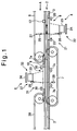
- a coin passage 2 through which coins 1 are transported is provided with a coin passage member 3 extending in the transporting direction of the coins 1 over the entire distance that the coins 1 are transported.
- the coin discriminating apparatus includes a first pattern data detection unit 4 and a second pattern data detection unit 5.
- the coin passage 2 is formed by the coin passage member 3 located below and a transporting belt 6 constituted as an endless round belt.
- the coin passage 2 is formed by a transporting belt 7 constituted as an endless belt located to project upward from an opening 7a formed in the coin passage member 3 and a coin passage forming member 8 located above the transporting belt 7 and extending in the transporting direction of coins 1.
- the coin passage member 3 where the first pattern data detection unit 4 is provided is formed with a first transparent passage portion 9 made of transparent glass, acrylic resin or the like and the coin passage forming member 8 is formed with a second transparent passage portion 10 made of transparent glass, acrylic resin or the like.
- Figure 2 is a schematic plan view of the first transparent passage portion 9.
- a coin 1 is fed to the first transparent passage portion 9 in the coin passage 2 along a pair of guide rails 11, 11 in the direction indicated by an arrow A by the transporting belt 6 located above the coin passage 2.
- a pair of magnetic sensors 12, 12 are provided for detecting magnetic properties of the coin 1 upstream of the first transparent passage portion 9 with respect to the coin transporting direction.
- the coin 1 is fed onto the first transparent passage portion 9, while being pressed onto the upper surface of the first transparent passage portion 9 by the transporting belt 6.
- a first light emitting means 21 including a plurality of light emitting elements 20 for emitting light toward the coin 1 passing through the first transparent passage portion 9 and a first image data producing means 22 below the first light emitting means 21 for receiving light emitted from the first light emitting means 21 and reflected by the coin 1 and producing image data.
- a first pattern data detection unit 4 is constituted by the first light emitting means 21 and the first image data producing means 22.
- the first light emitting means 21 is provided with the plurality of light emitting elements 20 such as light emitting diodes (LEDs) disposed on a circle whose center is at the center portion of the first transparent passage portion 9.
- Each light emitting element 20 is disposed in such a manner that the optical axis thereof is directed at a small angle with respect to the horizontal direction toward a predetermined point on a vertical axis passing through the center of a circle whose center coincides with the center portion of the first transparent passage portion 9, whereby light is projected onto the coin 1 passing through the first transparent passage portion 9 at a shallow angle with respect to the surface of the coin 1.
- the first image data producing means 22 includes a lens system 23 disposed so that the optical axis thereof coincides with the vertical axis passing through the center of the circle whose center coincides with the center portion of the first transparent passage portion 9, a color sensor 24 disposed below the lens system 23 so that the focus point thereof is located on the upper surface of the first transparent passage portion 9 and adapted for photoelectrically detecting light emitted from the light emitting elements 20 and reflected by the surface of the coin 1, and an A/D converter (not shown) for converting image data of the lower surface of the coin 1 obtained by photoelectrically detecting by the color sensor 24 into digital signals, thereby producing digitized image data of the lower surface of the coin 1.
- a two-dimensional CCD type color sensor is used as the color sensor 24.
- two timing sensors 27, 27 each of which includes a light emitting element 25 and a light receiving element 26 are provided so that light emitted from the light emitting element 25 can be detected through the first transparent passage portion 9 by the light receiving element 26 and each is constituted so as to output a timing signal when the light receiving element 26 does not receive light emitted from the light emitting element 25.
- Each of the timing sensors 27, 27 is disposed with respect to the first image data producing means 22 so that the center of the coin 1 is located at the center of the first transparent passage portion 9 when light emitted from the light emitting element 25 is blocked by the coin 1 being transported on the surface of the first transparent passage portion 9 and is not received by the light receiving element 26, thereby outputting a timing signal.
- the coin 1 is pressed onto the upper surface of the coin passage member 3 by the transporting belt 6 provided above the coin passage and is transported in the first transparent passage portion 9 and the portion downstream thereof.
- the lower surface of the coin 1 is supported by the transporting belt 7 located to project above the coin passage member 3 from the opening 7a formed in the coin passage member 3 and is transported in the coin passage 2 while it is being held between the transporting belt 6 and the transporting belt 7.
- the coin 1 is transported in the region of the downstream portion of the first transparent passage portion 9 and is fed to the second pattern data detection unit 5, while the upper surface of the coin 1 is supported by the coin passage forming member 8 and pressed onto the lower surface of the coin passage forming member 8 by the transporting belt 7.
- a plurality of back-up rollers 7b, 7c are provided for preventing the transporting belt 7 from being deflected downwardly due to the dead load of the coin 1.
- the second pattern data detection unit 5 is provided above the second transparent passage portion 10 and includes a second light emitting means 31 including a plurality of light emitting elements 30 for emitting light toward the coin 1 passing through the second transparent passage portion 10 and a second image data producing means 32 provided above the second transparent passage portion 10 for receiving light emitted from the second light emitting means 31 and reflected by the coin 1 and producing image data.
- the second light emitting means 31 is constituted in a similar manner to the first light emitting means 21 except that it is disposed above the second transparent passage portion 10 and emits light downwardly and includes a plurality of light emitting elements 30 such as light emitting diodes (LEDs) arranged on the circle whose center coincides with the center portion of the second transparent passage portion 10.
- LEDs light emitting diodes
- Each light emitting element 30 is disposed in such a manner that the optical axis thereof is directed at a small angle with respect to the horizontal direction toward a predetermined point on a vertical axis passing through the center of the circle whose center coincides with the center portion of the second transparent passage portion 10, whereby light is projected onto the coin 1 passing through the second transparent passage portion 10 at a shallow angle with respect to the surface of the coin 1.
- the second image data producing means 32 includes a lens system 33 disposed so that the optical axis thereof coincides with the vertical axis passing through the center of the circle whose center coincides with the center portion of the second transparent passage portion 10, a color sensor 34 disposed above the lens system 33 so that the focus point thereof is located on the lower surface of the second transparent passage portion 10 and adapted for photoelectrically detecting light emitted from the light emitting elements 30 and reflected by the surface of the coin 1, and an A/D converter (not shown) for converting image data of the upper surface of the coin 1 obtained by photoelectrically detecting by the color sensor 34 into digital signals, thereby producing digitized image data of the upper surface of the coin 1.
- a two-dimensional CCD type color sensor is used as the color sensor 34.
- two timing sensors 37, 37 each of which includes a light emitting element 35 and a light receiving element 36 are provided so that light emitted from the light emitting element 35 can be detected through the second transparent passage portion 10 by the light receiving element 36 and each is constituted so as to output a timing signal when the light receiving element 36 does not receive light emitted from the light emitting element 35.
- Each of the timing sensors 37 is disposed with respect to the second image data producing means 32 so that the center of the coin 1 is located at the center of the second transparent passage portion 10 when light emitted from the light emitting element 35 is blocked by the coin 1 being transported on the surface of the second transparent passage portion 10 and is not received by the light receiving element 36, thereby outputting a timing signal.
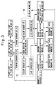
- Figure 3 is a block diagram of detection, control and discrimination systems of a coin discriminating apparatus which is a preferred embodiment of the present invention.
- the detection system of the coin discriminating apparatus includes the two timing sensors 27, 27 for detecting a coin 1 fed to the first transparent passage portion 9 and the two timing sensors 37, 37 for detecting a coin fed to the second transparent passage portion 10.
- the control system of the coin discriminating apparatus includes light emission control means 40 which outputs a light emission signal to the first light emitting means 21 when the timing signal from the timing sensors 27, 27 is received and causes it to emit light and illuminate the coin 1 located on the upper surface of the first transparent passage portion 9 and outputs a light emission signal to the second light emitting means 31 when the timing signal from the timing sensors 37, 37 is received and causes it to emit light and illuminate the coin 1 located on the lower surface of the second transparent passage portion 10, and image reading control means 41 for permitting the color sensor 24 of the first image data producing means 22 to start detecting the light reflected from the surface of the coin 1 when the timing signal from the timing sensors 27, 27 is received and permitting the color sensor 34 of the second image data producing means 32 to start detecting the light reflected from the surface of the coin 1 when the timing signal from the timing sensors 37, 37 is received.
- the discriminating system of the coin discriminating apparatus includes a first reference data memory 50 for storing reference magnetic data indicating magnetic properties of coins of each denomination; a second reference data memory 51 for storing reference data relating to the diameter of coins of each denomination, reference chromaticity data of coins of each denomination and reference lightness data of coins of each denomination; a third reference data memory 52 for storing reference ratio data showing the ratio of data "0" in the binary image pattern data groups corresponding to a plurality of annular areas on the surface of each denomination of coins; first discriminating means 53 which accesses the first reference data memory 50 in accordance with detection signals from the magnetic sensors 12, 12 and compares the reference magnetic data which indicate the magnetic properties of each denomination stored in the first reference data memory 50 with the magnetic data of the coin 1 input from the magnetic sensors 12, 12, thereby determining the denomination of the coin 1; second discriminating means 54 for discriminating the denomination of the coin 1 and the damage degree of the lower surface of the coin 1 based on the result of discrimination made by the first discriminating means 53, the reference data relating to
- the reference numeral 58 designates display means for displaying whether or not the coin 1 is acceptable and the damage degree of the coin 1 exceeds a predetermined level.
- a denomination discrimination signal is output from the first discriminating means 53 to the light emission control means 40 and the light emission control means 40 is constituted so as to control the amount of light emitted from the light emitting elements 20 and the light emitting elements 30 in accordance with the denomination discrimination signal input from the first discriminating means 53 based on the denomination of the coin 1 discriminated by the first discriminating means 53.
- the third reference data memory 52 the reference ratio data of the binary image pattern data groups corresponding to each annular area of obverse and reverse surfaces of all denominations to be processed are stored.
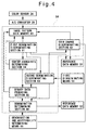
- Figure 4 is a block diagram of the second discriminating means 54.
- the second discriminating means 54 includes an image pattern data memory 60 for mapping and storing the image pattern data of the lower surface of the coin 1 photoelectrically detected by the color sensor 24 and digitized by the A/D converter 28 into an orthogonal coordinate system, i.e., an x-y coordinate system; a first denomination discriminating section 61 which accesses the second reference data memory 51 and compares the reference data relating to the diameter of the coin of each denomination stored in the second reference data memory 51 with the image pattern data of the lower surface of the coin 1 read from the image pattern data memory 60, thereby determining the denomination of the coin 1 based on the diameter of the coin 1 and outputting a denomination discrimination signal; a second denomination discriminating section 63 for discriminating the denomination of the coin 1 based on a denomination discrimination signal input from the first discriminating means 53 and a denomination discrimination signal input from the first denomination discriminating section 61 and outputting a denomination discrimination signal; a coin damage discriminating section 62 for calculating chromaticity data and lightness data
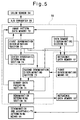
- Figure 5 is a block diagram of the third discriminating means 55.
- the third discriminating means 55 includes an image pattern data memory 70 for mapping and storing the image pattern data of the upper surface of the coin 1 photoelectrically detected by the color sensor 34 and digitized by the A/D converter 38 into the orthogonal coordinate system, i.e., the x-y coordinate system; a first denomination discriminating section 71 which accesses the second reference data memory 51 and compares the reference data relating to the diameter of the coin of each denomination stored in the second reference data memory 51 with the image pattern data of the upper surface of the coin 1 read from the image pattern data memory 70, thereby determining the denomination of the coin 1 based on the diameter of the coin 1 and outputting a denomination discrimination signal; a second denomination discriminating section 73 for discriminating the denomination of the coin 1 based on a denomination discrimination signal input from the first discriminating means 53 and a denomination discrimination signal input from the first denomination discriminating section 71 and outputting a denomination discrimination signal; a coin damage discriminating section 72 for calculating chromaticity data and lightness data of
- the thus constituted coin discriminating apparatus discriminates whether or not a coin 1 is acceptable, whether or not the coin 1 is damaged to higher than a predetermined level and the denomination of the coin 1.
- the coin 1 is pressed onto the upper surface of the coin passage member 3 by the transporting belt 6 and is fed in the coin passage 2 along a pair of guide rails 11, 11 in the direction indicated by an arrow A.
- the magnetic properties of the coin 1 are detected by the pair of magnetic sensors 12, 12 and the detection signals are output to the first discriminating means 53.
- the first discriminating means 53 accesses the first reference data memory 50 when the detection signals are input from the magnetic sensors 12, 12, reads the reference magnetic data which indicate the magnetic properties of each denomination stored in the first reference data memory 50, discriminates the denomination of the coin 1 by comparing the reference magnetic data read from the first reference data memory 50 with the magnetic data of the coin 1 input from the magnetic sensors 12, 12 and outputs denomination discrimination signals to the second discriminating means 54, the third discriminating means 55 and the light emission control means 40.
- timing signals are output from the timing sensors 27, 27 to the light emission control means 40 and the image reading control means 41.
- the light emission control means 40 When the timing signals are input from the timing sensors 27, 27, the light emission control means 40 outputs a light emission signal to the first light emitting means 21 based on the denomination discrimination signal from the first discriminating means 53 and causes the light emitting elements 20 to emit the amount of light that corresponds to the denomination of the coin 1 discriminated by the first discriminating means 53 toward the lower surface of the coin 1 located on the first transparent passage portion 9.
- the reason why the amount of emitted light from the light emitting elements 20 is controlled based on the discriminating result of the denomination of the coin 1 by the first discriminating means 53 is because the amount of reflected light changes depending upon the material of the coin 1. If the same amount of light is emitted toward the coin 1, the image pattern of the coin 1 cannot be accurately detected.
- the coin when the coin is made of a material having high light reflectivity such as nickel, aluminum or the like, it becomes difficult to accurately produce the binary data corresponding to the pattern of the surface of the coin 1 by detecting the reflected light from the surface of the coin 1. That is because the total amount of detected light becomes large and saturated if a large amount of light is illuminated.
- the coin when the coin is made of a material having low light reflectivity such as copper, brass or the like, the binary data corresponding to the pattern on the surface of the coin 1 cannot be accurately produced by detecting the reflected light from the surface of the coin 1. That is because the total amount of detected light is too little if a small amount of light is illuminated.
- the light emission control means 40 is constituted such that when the coin 1 of the denomination discriminated by the first discriminating means 53 is made of a material having high light reflectivity such as nickel, aluminum or the like, the light emission control means 40 outputs a light emission signal to the first light emitting means 21 so that the light emitting elements 20 emits low intensity of light.
- the light emission control means 40 outputs the light emission signal to the first light emitting means 21 so that the light emitting elements 20 emits high intensity of light.
- the image reading control means 41 causes the color sensor 24 of the first image data producing means 22 to start detecting the light emitted. from the light emitting elements 20 and reflected on the lower surface of the coin 1 when the timing signals from the timing sensors 27, 27 are input.
- the first light emitting means 21 is disposed so as to be able to illuminate the coin 1 which advances on the first transparent passage portion 9 at a shallow angle, the light is reflected according to the raised and depressed pattern of the lower surface of the coin 1.
- the light reflected from the surface of the coin 1 is directed toward the color sensor 24 by the lens system 23 and photoelectrically detected by the color sensor 24, whereby the image pattern data of the surface of the coin 1 are produced by the color sensor 24.
- the image pattern data of the surface of the coin 1 produced by the color sensor 24 are digitized by the A/D converter 28.
- the digitized image pattern data are mapped and stored in the orthogonal coordinate system, namely, x-y coordinate system in the image pattern data memory 60.
- the first denomination discriminating section 61 of the second discriminating means 54 accesses the second reference data memory 51. It reads the data stored in the with regard to the diameter of the coin 1 and also the image pattern data stored in the image pattern data memory 60. By comparing those data, the first denomination discriminating section 61 of the second discriminating means 54 determines the denomination of the coin 1 and outputs the denomination discrimination signal to the second denomination discriminating section 63.
- the denomination of the coin 1 There are some coins whose diameters are only slightly different from each other even though their denominations are different. When coins having a slightly larger diameter are worn out, their diameter can happen to coincide. Therefore, in some cases, the denomination of the coin 1 cannot be detected accurately by detecting its diameter.
- the first discriminating means 53 determines the denomination of the coin 1 based on the magnetic properties of the coin 1 and outputs the denomination discrimination signal to the second denomination discriminating section 63.
- the first denomination discriminating section 61 of the second discriminating means 54 determines the denomination of the coin 1 based on the diameter of the coin 1 and outputs the denomination discrimination signal to the second denomination discriminating section 63.
- the first denomination discriminating section 61 of the second discriminating means 54 determines only one kind of denomination of the coin 1 based on the diameter of the coin 1, produces the denomination discrimination signal and outputs it to the second denomination discriminating section 63, there is a possibility that the second denomination discriminating section 63 determines that the coin 1 is not acceptable even though the coin 1 is an acceptable coin. Accordingly, in this embodiment, the first denomination discriminating section 61 of the second discriminating means 54 selects two denominations whose diameters are the closest and the second closest to the diameter of the detected coin 1 and outputs the denomination discrimination signal to the second denomination discriminating section 63.
- the second denomination discriminating section 63 determines the denomination of the coin 1 based on the denomination discrimination signal input from the first discriminating means 53 and the denomination discrimination signal input from the first denomination discriminating section 61 of the second discriminating means 54.
- the second denomination discriminating section 63 outputs the denomination discrimination signal to the coin damage discriminating section 62, the binary data producing section 65 and the denomination determining section 66.
- the coin 1 is a counterfeit coin or a foreign coin and therefore, it determines that it is not acceptable and an unacceptable signal is output to the display means 58.
- the coin damage discriminating section 62 reads the image pattern data of the lower surface of the coin 1 stored in the image pattern data memory 60 and calculates the chromaticity data and the lightness data of the coin 1 based on the R, G and B data in the image pattern data.
- the coin damage discriminating section 62 accesses the second reference data memory 51, reads, based on the denomination discrimination signal input from the second denomination discriminating section 63, the reference chromaticity data and the reference lightness data of the coin having the denomination discriminated by the second denomination discriminating section 63 and compares the reference chromaticity data and the reference lightness data read from the second reference data memory 51 with the calculated chromaticity data and lightness data of the coin 1, thereby discriminating whether or not the coin 1 is damaged to higher than a predetermined level.
- the coin damage discriminating section 62 can discriminate whether or not the coin 1 is damaged to higher than a predetermined level by comparing the calculated chromaticity data and lightness data of the coin 1 with the reference chromaticity data and the reference lightness data.
- the coin damage discriminating section 62 determines that the coin 1 is damaged to higher than a predetermined level, it outputs a damage determination signal to the denomination and acceptability discriminating means 56. At the same time, the coin damage discriminating section 62 outputs the damage determination signal to the display means 58 and cause it to display that the coin 1 is damaged to higher than a predetermined level.
- the center coordinate determining section 64 determines the center coordinate of the image pattern data mapped and stored in the orthogonal coordinate system, namely, the x-y coordinate system and stored in the image pattern data memory 60 and outputs the center coordinate to the binary data producing section 65.
- the binary data producing section 65 reads the image pattern data of the lower surface of the coin 1 mapped and stored in the image pattern data memory 60 and binarizes them.
- the binary data producing section 65 groups the binarized image pattern data into the binary image pattern data groups of the denomination corresponding to the plurality of annular areas of the surface of the coin 1 based on the denomination discrimination signal input from the second denomination discriminating section 63 and the center coordinate signal input from the center coordinate determining section 64.
- the binary data producing section 65 further obtains the number of the "0" data in each binary image pattern data group corresponding to each annular area, obtains the ratio of the "0" data with respect to all the data, produces the ratio data of each binary image pattern data group corresponding to each annular area of the surface of the coin 1 and outputs the ratio data to the denomination determining section 66.
- the denomination determining section 66 When the denomination determining section 66 receives the denomination discrimination signal from the second denomination discriminating section 63, it accesses the third reference data memory 52, at first, reads the reference ratio data of the reverse surface of the coin of the corresponding denomination from the reference ratio data stored in the third reference data memory 52 in accordance with the denomination discrimination signal input from the second denomination discriminating section 63, and compares the reference ratio data with the ratio data input from the binary data producing section 65, thereby discriminating the denomination of the coin 1.
- the denomination determining section 66 further integrates the absolute values Di of the differences between the reference ratio data and the ratio data over all of the binary image pattern data groups corresponding to the annular areas of the coin 1, and determines whether or not the resulted integrated value I is less than a predetermined value I0. As a result, when the integrated value I is less than the predetermined value I0, the denomination determining section 66 determines that the coin 1 is the coin of the denomination determined by the second denomination discriminating section 63.
- the coin 1 cannot be always fed such that its obverse surface faces upward and there are cases where the obverse surface of the coin 1 faces downward while it is advanced in the coin passage 2. As a result, there is a possibility that the surface pattern of the obverse surface of the coin 1 may be detected by the color sensor 24. Therefore, to determine that the coin 1 is not acceptable when the detected ratio data of the coin 1 do not coincide with the reference ratio data of the reverse surface of the coin of the denomination determined by the second denomination discriminating section 63 will significantly lower discriminating accuracy.
- the denomination determining section 66 further accesses the third reference data memory 52, reads the reference ratio data of the obverse surface of the coin of the denomination determined by the second denomination discriminating section 63, and, in the exactly same manner as described above, it determines whether or not the absolute values Di of the differences between the reference ratio data of each binary image pattern group corresponding to each annular area of the coin 1 and the detected ratio data are less than a predetermined value D0.
- the denomination determining section 66 integrates the absolute values Di of the differences between the reference ratio data of all the binary image pattern groups corresponding to each annular area of the coin 1, and determines whether or not the resulted integrated value I is less than the predetermined value I0. As a result, when the integrated value I is less than the predetermined value I0, the denomination determining section 66 determines that the coin 1 is the coin of the denomination determined by the second denomination discriminating section 63.
- the denomination determining section 66 outputs the unacceptable signal
- the denomination determining section 66 determines that the coin 1 is acceptable, it outputs a denomination determination signal to the denomination and acceptability determining means 56.
- the coin is further fed downstream in the coin passage 2 by the transporting belt 6 and the lower surface thereof is supported by the transporting belt 7 disposed to project above the coin passage member 3 from the opening 7a formed in the coin passage member 3.
- the coin 1 is fed while it is being held between the transporting belt 6 and the transporting belt 7.
- the coin 1 is then pressed onto the lower surface of the coin passage forming member 8 by the transporting belt 7 and transported to the second transparent passage portion 10.
- timing signals are output from the timing sensors 37, 37 to the light emission control means 40 and the image reading control means 41.
- the light emission control means 40 When the light emission control means 40 receives the timing signals from the timing sensors 37, 37, it outputs a light emission signal to the second light emitting means 31 based on the denomination discrimination signal from the first discriminating means 53 and causes the light emitting elements 30 to emit the amount of light that corresponds to the denomination of the coin 1 discriminated by the first discriminating means 53 toward the upper surface of the coin 1 located on the second transparent passage portion 10.
- the image reading control means 41 When the image reading control means 41 receives the timing signals from the timing sensors 37, 37, it causes the color sensor 34 of the second image data producing means 32 to start detecting the light emitted from the light emitting elements 30 and reflected on the upper surface of the coin 1.
- the amount of light emitted from the light emitting elements 30 is controlled by the light emission control means 40 based on the denomination discrimination signal input from the first discriminating means 53 in the exactly same manner as described above as to the light emitting elements 20 of the first light emitting means 21.
- the second light emitting means 31 is disposed so as to be able to illuminate the coin 1 which advances on the second transparent passage portion 10 at a shallow angle, the light is reflected according to the raised and depressed pattern of the upper surface of the coin 1.
- the light reflected from the surface of the coin 1 is directed toward the color sensor 34 by the lens system 33 and photoelectrically detected by the color sensor 34, whereby the image pattern data of the surface of the coin 1 are produced by the color sensor 34.
- the image pattern data of the surface of the coin 1 produced by the color sensor 34 are digitized by the A/D converter 38.
- the digitized image pattern data are mapped and stored in the orthogonal coordinate system, namely, x-y coordinate system in the image pattern data memory 70.
- the first denomination discriminating section 71 of the third discriminating means 55 accesses the second reference data memory 51. It reads the data stored in the second reference data memory 51 with regard to the diameter of the coin 1 and also the image pattern data stored in the image pattern data memory 70. By comparing those data, the first denomination discriminating section 71 of the third discriminating means 55 determines the denomination of the coin 1 and outputs a denomination discrimination signal to the second denomination discriminating section 73.
- the first denomination discriminating section 71 of the third discriminating means 55 selects two denominations, whose diameters are the closest and the second closest to the diameter of the detected coin 1 and outputs the denomination discrimination signal to the second denomination discriminating section 73.
- the second denomination discriminating section 73 determines the denomination of the coin 1 based on the denomination discrimination signal input from the first discriminating means 53 and the denomination discrimination signal input from the first denomination discriminating section 71 of the third discriminating means 55.
- the second denomination discriminating section 73 outputs a denomination discrimination signal to the coin damage discriminating section 72, the binary data producing section 75 and the denomination determining section 76.
- the coin 1 is a counterfeit coin or a foreign coin and, therefore, it determines that it is not acceptable and an unacceptable signal is output to the display means 58.
- the coin damage discriminating section 72 reads the image pattern data of the upper surface of the coin 1 stored in the image pattern data memory 70 and calculates the chromaticity data and the lightness data of the coin 1 based on the R, G and B data in the image pattern data. Further, the coin damage discriminating section 72 accesses the second reference data memory 51, reads, based on the denomination discrimination signal input from the second denomination discriminating section 73, the reference chromaticity data and the reference lightness data of the coin having the denomination discriminated by the second denomination discriminating section 73 and compares the reference chromaticity data and the reference lightness data read from the second reference data memory 51 with the calculated chromaticity data and lightness data of the coin 1, thereby discriminating whether or not the coin 1 is damaged to higher than a predetermined level.
- the coin damage discriminating section 72 determines that the coin 1 is damaged to higher than a predetermined level, it outputs a damage determination signal to the denomination and acceptability discriminating means 56. At the same time, the coin damage discriminating section 52 outputs the damage determination signal to the display means 58 and cause it to display that the coin 1 is damaged to higher than a predetermined level.
- the center coordinate determining section 74 determines the center coordinate of the image pattern data mapped and stored in the orthogonal coordinate system, namely, the x-y coordinate system, and stored in the image pattern data memory 70 and outputs the center coordinate to the binary data producing section 75.
- the binary data producing section 75 reads the image pattern data of the upper surface of the coin 1 mapped and stored in the image pattern data memory 70 and binarizes them.
- the binary data producing section 75 groups the binarized image pattern data into the binary image pattern data groups of the denomination corresponding to the plurality of annular areas of the surface of the coin 1 based on the denomination discrimination signal input from the second denomination discriminating section 73 and the center coordinate signal input from the center coordinate determining section 74.
- the binary data producing section 75 further obtains the number of the "0" data in each binary image pattern data group corresponding to each annular area, obtains the ratio of the "0" data with respect to all the data, produces the ratio data of each binary image pattern data group corresponding to each annular area of the surface of the coin 1 and outputs the ratio data to the denomination determining section 76.
- the denomination determining section 76 When the denomination determining section 76 receives the denomination discrimination signal from the second denomination discriminating section 73, it accesses the third reference data memory 52, reads the reference ratio data of the obverse and reverse surfaces of the coin of the corresponding denomination from the reference ratio data stored in the third reference data memory 52 in accordance with the denomination discrimination signal input from the second denomination discriminating section 73, and compares the reference ratio data with the ratio data input from the binary data producing section 75, thereby discriminating the denomination of the coin 1 in the exactly same manner as described above as to the denomination determining section 66 of the second discriminating means 54.
- the denomination determining section 76 determines that the coin 1 is a counterfeit coin or a foreign coin and that it is not acceptable, it outputs an unacceptable signal to the display means 58 and causes it to display that the coin 1 is not acceptable.
- the denomination determining section 76 determines that the coin 1 is acceptable, it outputs a denomination determination signal to the denomination and acceptability determining means 56.
- the denomination and acceptability determining means 56 makes the discrimination of the coin 1 based on the denomination discrimination signal input from the first discriminating means 53 and based on the magnetic properties of the coin 1, the denomination discrimination signal input from the denomination determining section 66 of the second discriminating means 54 and based on the diameter data and the image pattern data of the coin 1, the presence of the damage discrimination signal input from the coin damage discriminating section 62 and based on the chromaticity data and the lightness data of the coin 1, the denomination discrimination signal input from the denomination determining section 76 of the third discriminating means 55 and based on the diameter data and the image pattern data of the coin 1 and the presence of the damage discrimination signal input from the coin damage discriminating section 72 and based on the chromaticity data and the lightness data of the coin 1.
- the denomination and acceptability determining means 56 finds that the denominations determined by the first discriminating means 53, the second discriminating means 54 and the third discriminating means 55 coincide with each other, it discriminates that the coin 1 is acceptable. On the other hand, when they do not coincide with each other, the denomination and acceptability determining means 56 discriminates that the coin 1 is either a counterfeit coin or a foreign coin and is not acceptable and outputs an unacceptable signal to the display means 58 to cause it to display that the coin 1 is not acceptable. More specifically, for example, when the second discriminating means 54 discriminates that the pattern data of the lower surface of the coin 1 coincide with the reference pattern of the obverse surface of a coin of a certain denomination and the third.
- the denomination and acceptability determining means 56 determines that the coin 1 is acceptable only when the denomination of the coin 1 determined by the second discriminating means 54 and the third discriminating means 55 coincides with the denomination of the coin 1 determined by the first discriminating means 53 and determines that the coin 1 is the coin of the denomination determined by the first discriminating means 53, the second discriminating means 54 and the third discriminating means 55. Otherwise, the denomination and acceptability determining means 56 determines that the coin 1 is an unacceptable coin.
- coins discriminated as unacceptable are sorted and collected separately from coins discriminated as acceptable. Further, even though it is discriminated that a coin is acceptable, when it is discriminated that at least one surface thereof is damaged to higher than a predetermined level, it is collected separately from coins discriminated as acceptable.
- a coin 1 in the region of the first pattern data detection unit 4, a coin 1 is transported while it is being pressed onto the upper surface of the first transparent passage portion 9 formed in the coin passage member 3 by the transporting belt 6 and is irradiated via the first transparent portion 9 with light emitted from the light emitting elements 20 disposed below the coin passage member 3 and light reflected from the lower surface of the coin 1 is photoelectrically detected by the color sensor 24, thereby producing pattern data of the lower surface of the coin 1.
- the coin 1 is transported while the lower surface thereof is being supported by the transporting belt 7 disposed to project above the coin passage member 3 from the opening 7a formed in the coin passage member 3 so that it is being pressed onto the lower surface of the coin passage forming member 8 provided above the transporting belt 7 and is irradiated via the second transparent passage portion 10 formed in the coin passage forming member 8 with light emitted from the light emitting elements 30 disposed above the coin passage forming member 8 and light reflected from the upper surface of the coin 1 is photoelectrically detected by the color sensor 34, thereby producing pattern data of the upper surface of the coin 1.
- patterns of both surfaces of the coin 1 are detected for discriminating whether or not the coin 1 is acceptable. Therefore, it is possible to sort coins such as Euro coins on one surface of which a common pattern is formed and on the other surface of which a different pattern is formed depending upon the issuing countries, into coins of each issuing country, as occasion demands. Further, since patterns of both surfaces of a coin 1 are detected for discriminating whether or not the coin 1 is damaged to higher than a predetermined level, it is possible to reliably discriminate the coin one of the surfaces of which is damaged to higher than a predetermined level as a damaged coin and collect it.
- the first discriminating means 53 discriminates the denomination of a coin 1 based on magnetic properties of the coin 1 detected by the magnetic sensors 12, 12,
- the first denomination discriminating section 61 of the second discriminating means 54 discriminates the denomination of the coin 1 based on the diameter of the coin 1
- the second denomination discriminating section 63 of the second discriminating means 54 is constituted so as to tentatively determine the denomination of the coin 1 based on the discriminating results made by the first discriminating means 53 and the first denomination discriminating section 61 of the second discriminating means 54.
- the denomination determining section 66 of the second discriminating means 54 discriminates the denomination of the coin 1 by comparing the pattern data of the coin 1 with only the reference data of the coin of the denomination determined by the first denomination discriminating section 61 of the second discriminating means 54 and the third discriminating means 55 discriminates the denomination of the coin 1 in the same manner as in the second discriminating means 54. Whether or not the coin 1 is acceptable and the denomination of the coin 1 are finally discriminated based on the discriminating results made by the first discriminating means 53, the second discriminating means 54 and the third discriminating means 55.
- the denomination of the coin 1 and whether or not the coin 1 is acceptable are determined. Therefore, even in the case where the coin 1 is rotated with respect to the reference position, without rotating the resulted pattern data of the coin 1 in order to compare with the reference pattern data, it is possible to determine the denomination of the coin 1 and whether or not the coin 1 is acceptable in a shorter time.
- Figure 6 is a schematic longitudinal cross-sectional view of a coin discriminating apparatus which is another preferred embodiment of the present invention.
- the coin passage member 3 is cut off over a region extending from an upstream portion of the second pattern data detection unit 5 to a downstream portion thereof and a transporting belt 7 is provided there so as to be disposed above the upper surface of the coin passage member 3. Therefore, a coin 1 which has been transported by the transporting belt 6 while the lower surface thereof has been supported by the upper surface of the coin passage member 3 is fed to the second pattern data detection unit 5 while the lower surface thereof is being supported by the transporting belt 7.
- the coin 1 is further fed downstream in the coin passage 2 while it is being pressed onto the upper surface of the coin passage member 3 by a transporting belt 39.
- a coin 1 in the region of the first pattern data detection unit 4, a coin 1 is transported while it is being pressed onto the upper surface of the first transparent passage portion 9 formed in the coin passage member 3 by the transporting belt 6 and is irradiated via the first transparent portion 9 with light emitted from the light emitting elements 20 disposed below the coin passage member 3 and light reflected from the lower surface of the coin 1 is photoelectrically detected by the color sensor 24, thereby producing pattern data of the lower surface of the coin 1.
- the coin 1 is delivered from the coin passage member 3 onto transporting belt 7 and transported while the lower surface thereof is being supported by the transporting belt 7 so that it is being pressed onto the lower surface of the coin passage forming member 8 provided above the transporting belt 7 and is irradiated via the second transparent passage portion 10 formed in the coin passage forming member 8 with light emitted from the light emitting elements 30 disposed above the coin passage forming member 8 and light reflected from the upper surface of the coin 1 is photoelectrically detected by the color sensor 34, thereby producing pattern data of the upper surface of the coin 1.
- the denomination of a coin 1 and whether or not a coin 1 is acceptable are discriminated by comparing ratio data obtained by photoelectrically detecting patterns of both surfaces of the coin 1 and calculating a ratio of the "0" data in each pattern data group corresponding to each annular area with the reference ratio data determined in advance.
- ratio data obtained by photoelectrically detecting patterns of both surfaces of the coin 1 and calculating a ratio of the "0" data in each pattern data group corresponding to each annular area with the reference ratio data determined in advance.
- the region of the first coin damage degree discriminating unit similarly to the region of the first pattern data detection unit 4, so as to form a third transparent passage portion in the coin passage member 3 constituting the lower surface of the coin passage 2 so that a coin 1 is transported while it is being pressed onto the upper surface of the coin passage member 3 by a transporting belt provided above the coin passage member 3 and provide, below the third transparent passage portion, a white light source for illuminating white light onto the lower surface of the coin 1 via the third transparent passage portion and a single-element type color sensor for detecting light emitted from the white light source and reflected from the lower surface of the coin 1, and to constitute the region of the second coin damage degree discriminating unit so as to support the lower surface of the coin 1 by a transporting belt provided to project upward from an opening formed in the coin passage member 3 or a transporting belt provided in a portion where the coin passage member 3 is cut off and disposed above the upper surface of the coin passage member 3, form a fourth transparent passage portion in the coin passage forming
- a first coin damage degree discriminating unit for discriminating damage degree of the lower surface of the coin 1
- the first coin damage degree discriminating unit comprising a photosensor, a first LED light source for emitting light corresponding to R component, a second LED light source for emitting light corresponding to G component and a third LED light source for emitting light corresponding to B component, the first LED light source, the second LED light source and the third LED light source being disposed around the photosensor and spaced from each other by 120 degrees
- a second coin damage degree discriminating unit for discriminating damage degree of the upper surface of the coin 1
- the second coin damage degree discriminating unit comprising a photosensor, a first LED light source
- the region of the first coin damage degree discriminating unit similarly to the region of the first pattern data detection unit 4, so as to form a third transparent passage portion in the coin passage member 3 constituting the lower surface of the coin passage 2 so that a coin 1 is transported while it is being pressed onto the upper surface of the coin passage member 3 by a transporting belt provided above the coin passage member 3 and to constitute the region of the second coin damage degree discriminating unit so as to support the lower surface of the coin 1 by a transporting belt provided to project upward from an opening formed in the coin passage member 3 or a transporting belt provided in a portion where the coin passage member 3 is cut off and disposed above the upper surface of the coin passage member 3, form a fourth transparent passage portion in the coin passage forming member 8 provided above the transporting belt, press the coin 1 onto the lower surface of the coin passage forming member 8, thereby transporting it, and damage degree of each surface of the coin 1 can be discriminated by producing chromaticity data and lightness data based on R data, G data and B data of each
- the first pattern data detection unit 4 is provided upstream of the second pattern data detection unit 5 with respect to the transporting direction of the coin 1, it is not absolutely necessary to provide the first pattern data detection unit 4 upstream of the second pattern data detection unit 5 and the first pattern data detection unit 4 may be provided downstream of the second pattern data detection unit 5.
- the first coin damage degree discriminating unit may be provided upstream of the second coin damage degree discriminating unit or the second coin damage degree discriminating unit may be provided upstream of the first coin damage degree discriminating unit. Namely, it is possible to arbitrarily determine the positional relationship between the first pattern data detection unit 4 and the second pattern data detection unit 5 and the positional relationship between the first coin damage degree discriminating unit and the second coin damage degree discriminating unit.
- the respective means need not necessarily be physical means and arrangements whereby the functions of the respective means are accomplished by software fall within the scope of the present invention.
- the function of a single means may be accomplished by two or more physical means and the functions of two or more means may be accomplished by a single physical means.
- the present invention it is possible to provide a coin discriminating apparatus capable of discriminating whether or not coins are acceptable and the denominations of coins with high accuracy even when the coins has a common pattern on one side surface thereof but a different pattern on the other side surface thereof like Euro coins.
Applications Claiming Priority (2)
| Application Number | Priority Date | Filing Date | Title |
|---|---|---|---|
| JP23032599A JP3652558B2 (ja) | 1999-08-17 | 1999-08-17 | 硬貨判別装置 |
| JP23032599 | 1999-08-17 |
Publications (2)
| Publication Number | Publication Date |
|---|---|
| EP1077434A1 true EP1077434A1 (fr) | 2001-02-21 |
| EP1077434B1 EP1077434B1 (fr) | 2004-06-09 |
Family
ID=16906073
Family Applications (1)
| Application Number | Title | Priority Date | Filing Date |
|---|---|---|---|
| EP00116815A Expired - Lifetime EP1077434B1 (fr) | 1999-08-17 | 2000-08-03 | Dispositif discriminateur de pièces de monnaie |
Country Status (8)
| Country | Link |
|---|---|
| US (1) | US6484865B1 (fr) |
| EP (1) | EP1077434B1 (fr) |
| JP (1) | JP3652558B2 (fr) |
| KR (1) | KR20010030081A (fr) |
| CN (1) | CN1178174C (fr) |
| DE (1) | DE60011353T2 (fr) |
| HK (1) | HK1033490A1 (fr) |
| TW (1) | TW463137B (fr) |
Cited By (2)
| Publication number | Priority date | Publication date | Assignee | Title |
|---|---|---|---|---|
| EP1388821A2 (fr) * | 2002-08-09 | 2004-02-11 | Laurel Precision Machines Co. Ltd. | Dispositif et procédé de reconnaissance de pièces de monnaie |
| WO2009025963A1 (fr) * | 2007-08-17 | 2009-02-26 | Talaris Inc. | Procédé et capteur pour détecter des pièces de monnaie pour évaluation |
Families Citing this family (25)
| Publication number | Priority date | Publication date | Assignee | Title |
|---|---|---|---|---|
| JP2002109596A (ja) * | 2000-09-28 | 2002-04-12 | Nippon Conlux Co Ltd | 貨幣識別方法及び装置 |
| JP2002324259A (ja) * | 2001-04-25 | 2002-11-08 | Nippon Conlux Co Ltd | 硬貨識別方法および装置 |
| JP2002324260A (ja) * | 2001-04-25 | 2002-11-08 | Nippon Conlux Co Ltd | 硬貨識別方法および装置 |
| TW564376B (en) * | 2002-07-05 | 2003-12-01 | Sunplus Technology Co Ltd | Currency recognition device and the method thereof |
| JP4176611B2 (ja) * | 2003-10-20 | 2008-11-05 | ローレル機械株式会社 | 硬貨判別方法および装置 |
| JP4709633B2 (ja) * | 2005-11-07 | 2011-06-22 | 日立オムロンターミナルソリューションズ株式会社 | 現金取引装置及び取引方法 |
| JP4921872B2 (ja) * | 2006-07-05 | 2012-04-25 | グローリー株式会社 | メダル計数機 |
| JP2008090391A (ja) * | 2006-09-29 | 2008-04-17 | Ac Holdings Japan Kk | コイン選別装置 |
| JP2009005312A (ja) * | 2007-06-25 | 2009-01-08 | Canon Inc | 画像処理装置及び画像処理方法及びコンピュータプログラム及び記憶媒体 |
| US8708129B2 (en) * | 2007-08-17 | 2014-04-29 | Talaris, Inc. | Method and system for dust prevention in a coin handling machine |
| KR100956742B1 (ko) | 2008-01-11 | 2010-05-06 | 주식회사 디에이테크놀로지 | 주화의 문양, 색상 및 두께 검사 장치 |
| US20090255776A1 (en) * | 2008-04-11 | 2009-10-15 | Nihon Unica Corporation | Coin authenticity judging method and device |
| WO2010007658A1 (fr) * | 2008-07-14 | 2010-01-21 | グローリー株式会社 | Dispositif d'identification de pièce de monnaie et procédé d'identification de pièce de monnaie |
| CN101789146B (zh) * | 2009-01-23 | 2012-09-05 | 北京凌云光视数字图像技术有限公司 | 对拍式硬币检查机和硬币检查方法 |
| WO2012036956A1 (fr) * | 2010-09-15 | 2012-03-22 | Identicoin, Inc. | Procédé et appareil d'identification de pièces |
| JP2012212222A (ja) * | 2011-03-30 | 2012-11-01 | Fujifilm Corp | 被写体識別装置、及び硬貨識別装置 |
| CN102207467B (zh) * | 2011-04-02 | 2013-08-07 | 云南昆船设计研究院 | 白饼在线检测剔除的方法及装置 |
| JP4943555B1 (ja) * | 2011-11-18 | 2012-05-30 | Kpe株式会社 | 遊技機およびメダルセレクター |
| JP5474235B1 (ja) * | 2013-05-14 | 2014-04-16 | Kpe株式会社 | メダルセレクタおよび遊技機 |
| CN103927813B (zh) * | 2014-04-24 | 2016-05-25 | 中国人民银行印制科学技术研究所 | 片状材料成像装置及使用该装置的清分机 |
| US10685523B1 (en) * | 2014-07-09 | 2020-06-16 | Cummins-Allison Corp. | Systems, methods and devices for processing batches of coins utilizing coin imaging sensor assemblies |
| CN106226320B (zh) * | 2016-08-30 | 2023-07-21 | 南京中钞长城金融设备有限公司 | 贵金属检查机 |
| JP6819382B2 (ja) * | 2017-03-16 | 2021-01-27 | 富士電機株式会社 | 硬貨検銭装置 |
| JP6433093B2 (ja) * | 2017-05-08 | 2018-12-05 | ローレル精機株式会社 | 硬貨処理装置 |
| JP7192424B2 (ja) * | 2018-11-16 | 2022-12-20 | 沖電気工業株式会社 | 硬貨処理装置及び自動取引装置 |
Citations (5)
| Publication number | Priority date | Publication date | Assignee | Title |
|---|---|---|---|---|
| JPH06150104A (ja) * | 1992-11-13 | 1994-05-31 | Laurel Bank Mach Co Ltd | 貨幣パターン検出装置 |
| EP0683473A2 (fr) * | 1994-05-19 | 1995-11-22 | Laurel Bank Machines Co., Ltd. | Dispositif discriminateur de pièces de monnaie |
| JPH0997363A (ja) * | 1995-10-02 | 1997-04-08 | Oki Electric Ind Co Ltd | 硬貨撮像装置 |
| JPH10222716A (ja) * | 1997-02-04 | 1998-08-21 | Sankyo Seiki Mfg Co Ltd | コイン認識装置 |
| EP1049054A2 (fr) * | 1999-04-26 | 2000-11-02 | Laurel Bank Machines Co., Ltd. | Dispositif discriminateur de pièces de monnaie |
Family Cites Families (3)
| Publication number | Priority date | Publication date | Assignee | Title |
|---|---|---|---|---|
| DE4314596C1 (de) * | 1993-05-04 | 1994-10-27 | Nat Rejectors Gmbh | Vorrichtung zum Festlegen von Sensorelementen in elektronischen Münzprüfgeräten |
| US5729623A (en) * | 1993-10-18 | 1998-03-17 | Glory Kogyo Kabushiki Kaisha | Pattern recognition apparatus and method of optimizing mask for pattern recognition according to genetic algorithm |
| JP3105725B2 (ja) * | 1993-12-27 | 2000-11-06 | 株式会社日本コンラックス | 紙幣識別装置 |
-
1999
- 1999-08-17 JP JP23032599A patent/JP3652558B2/ja not_active Expired - Fee Related
-
2000
- 2000-08-03 DE DE60011353T patent/DE60011353T2/de not_active Expired - Lifetime
- 2000-08-03 EP EP00116815A patent/EP1077434B1/fr not_active Expired - Lifetime
- 2000-08-04 TW TW089115745A patent/TW463137B/zh not_active IP Right Cessation
- 2000-08-11 KR KR1020000046577A patent/KR20010030081A/ko not_active Application Discontinuation
- 2000-08-14 US US09/638,640 patent/US6484865B1/en not_active Expired - Lifetime
- 2000-08-17 CN CNB001241451A patent/CN1178174C/zh not_active Expired - Lifetime
-
2001
- 2001-06-18 HK HK01104168A patent/HK1033490A1/xx not_active IP Right Cessation
Patent Citations (6)
| Publication number | Priority date | Publication date | Assignee | Title |
|---|---|---|---|---|
| JPH06150104A (ja) * | 1992-11-13 | 1994-05-31 | Laurel Bank Mach Co Ltd | 貨幣パターン検出装置 |
| EP0683473A2 (fr) * | 1994-05-19 | 1995-11-22 | Laurel Bank Machines Co., Ltd. | Dispositif discriminateur de pièces de monnaie |
| US5538123A (en) | 1994-05-19 | 1996-07-23 | Laurel Bank Machines Co:, Ltd. | Coin discriminating apparatus |
| JPH0997363A (ja) * | 1995-10-02 | 1997-04-08 | Oki Electric Ind Co Ltd | 硬貨撮像装置 |
| JPH10222716A (ja) * | 1997-02-04 | 1998-08-21 | Sankyo Seiki Mfg Co Ltd | コイン認識装置 |
| EP1049054A2 (fr) * | 1999-04-26 | 2000-11-02 | Laurel Bank Machines Co., Ltd. | Dispositif discriminateur de pièces de monnaie |
Non-Patent Citations (3)
| Title |
|---|
| PATENT ABSTRACTS OF JAPAN vol. 018, no. 466 (P - 1794) 30 August 1994 (1994-08-30) * |
| PATENT ABSTRACTS OF JAPAN vol. 1997, no. 08 29 August 1997 (1997-08-29) * |
| PATENT ABSTRACTS OF JAPAN vol. 1998, no. 13 30 November 1998 (1998-11-30) * |
Cited By (5)
| Publication number | Priority date | Publication date | Assignee | Title |
|---|---|---|---|---|
| EP1388821A2 (fr) * | 2002-08-09 | 2004-02-11 | Laurel Precision Machines Co. Ltd. | Dispositif et procédé de reconnaissance de pièces de monnaie |
| EP1388821A3 (fr) * | 2002-08-09 | 2004-07-07 | Laurel Precision Machines Co. Ltd. | Dispositif et procédé de reconnaissance de pièces de monnaie |
| US7209582B2 (en) | 2002-08-09 | 2007-04-24 | Laurel Precision Machines Co., Ltd. | Coin discriminating method and apparatus |
| WO2009025963A1 (fr) * | 2007-08-17 | 2009-02-26 | Talaris Inc. | Procédé et capteur pour détecter des pièces de monnaie pour évaluation |
| US8210337B2 (en) | 2007-08-17 | 2012-07-03 | Talaris Inc. | Method and sensor for sensing coins for valuation |
Also Published As
| Publication number | Publication date |
|---|---|
| KR20010030081A (ko) | 2001-04-16 |
| CN1178174C (zh) | 2004-12-01 |
| EP1077434B1 (fr) | 2004-06-09 |
| JP3652558B2 (ja) | 2005-05-25 |
| DE60011353T2 (de) | 2004-10-07 |
| TW463137B (en) | 2001-11-11 |
| DE60011353D1 (de) | 2004-07-15 |
| CN1284691A (zh) | 2001-02-21 |
| JP2001052231A (ja) | 2001-02-23 |
| US6484865B1 (en) | 2002-11-26 |
| HK1033490A1 (en) | 2001-08-31 |
Similar Documents
| Publication | Publication Date | Title |
|---|---|---|
| US6484865B1 (en) | Coin discriminating apparatus | |
| US6328150B1 (en) | Coin discriminating apparatus | |
| US6412620B1 (en) | Coin discriminating apparatus | |
| EP0683473B1 (fr) | Dispositif discriminateur de pièces de monnaie | |
| US6499581B2 (en) | Coin discriminating apparatus | |
| EP1490828B1 (fr) | Procede de verification du papier-monnaie | |
| US7209582B2 (en) | Coin discriminating method and apparatus | |
| US6431341B1 (en) | Coin discriminating apparatus | |
| JP5558150B2 (ja) | 硬貨処理機用の硬貨判別装置 | |
| JPH09218968A (ja) | 硬貨識別装置 | |
| JP2002183791A (ja) | 硬貨の識別方法及び装置 | |
| JPH1083471A (ja) | コイン識別装置 | |
| JPH09167270A (ja) | コイン識別装置 | |
| JPH10111965A (ja) | 物体の汚損状態判別方法およびその装置 |
Legal Events
| Date | Code | Title | Description |
|---|---|---|---|
| PUAI | Public reference made under article 153(3) epc to a published international application that has entered the european phase |
Free format text: ORIGINAL CODE: 0009012 |
|
| AK | Designated contracting states |
Kind code of ref document: A1 Designated state(s): DE FR GB |
|
| AX | Request for extension of the european patent |
Free format text: AL;LT;LV;MK;RO;SI |
|
| 17P | Request for examination filed |
Effective date: 20010409 |
|
| AKX | Designation fees paid |
Free format text: DE FR GB |
|
| 17Q | First examination report despatched |
Effective date: 20020206 |
|
| GRAP | Despatch of communication of intention to grant a patent |
Free format text: ORIGINAL CODE: EPIDOSNIGR1 |
|
| GRAS | Grant fee paid |
Free format text: ORIGINAL CODE: EPIDOSNIGR3 |
|
| GRAA | (expected) grant |
Free format text: ORIGINAL CODE: 0009210 |
|
| AK | Designated contracting states |
Kind code of ref document: B1 Designated state(s): DE FR GB |
|
| REG | Reference to a national code |
Ref country code: GB Ref legal event code: FG4D |
|
| REF | Corresponds to: |
Ref document number: 60011353 Country of ref document: DE Date of ref document: 20040715 Kind code of ref document: P |
|
| ET | Fr: translation filed | ||
| PLBE | No opposition filed within time limit |
Free format text: ORIGINAL CODE: 0009261 |
|
| STAA | Information on the status of an ep patent application or granted ep patent |
Free format text: STATUS: NO OPPOSITION FILED WITHIN TIME LIMIT |
|
| 26N | No opposition filed |
Effective date: 20050310 |
|
| REG | Reference to a national code |
Ref country code: FR Ref legal event code: PLFP Year of fee payment: 17 |
|
| REG | Reference to a national code |
Ref country code: FR Ref legal event code: PLFP Year of fee payment: 18 |
|
| REG | Reference to a national code |
Ref country code: FR Ref legal event code: PLFP Year of fee payment: 19 |
|
| PGFP | Annual fee paid to national office [announced via postgrant information from national office to epo] |
Ref country code: FR Payment date: 20190524 Year of fee payment: 20 |
|
| PGFP | Annual fee paid to national office [announced via postgrant information from national office to epo] |
Ref country code: DE Payment date: 20190828 Year of fee payment: 20 |
|
| PGFP | Annual fee paid to national office [announced via postgrant information from national office to epo] |
Ref country code: GB Payment date: 20190827 Year of fee payment: 20 |
|
| REG | Reference to a national code |
Ref country code: DE Ref legal event code: R071 Ref document number: 60011353 Country of ref document: DE |
|
| REG | Reference to a national code |
Ref country code: GB Ref legal event code: PE20 Expiry date: 20200802 |
|
| PG25 | Lapsed in a contracting state [announced via postgrant information from national office to epo] |
Ref country code: GB Free format text: LAPSE BECAUSE OF EXPIRATION OF PROTECTION Effective date: 20200802 |