EP1070374B1 - Dispositif et procede de denudage - Google Patents
Dispositif et procede de denudage Download PDFInfo
- Publication number
- EP1070374B1 EP1070374B1 EP99909133A EP99909133A EP1070374B1 EP 1070374 B1 EP1070374 B1 EP 1070374B1 EP 99909133 A EP99909133 A EP 99909133A EP 99909133 A EP99909133 A EP 99909133A EP 1070374 B1 EP1070374 B1 EP 1070374B1
- Authority
- EP
- European Patent Office
- Prior art keywords
- cable
- jaws
- blade
- stripping
- blades
- Prior art date
- Legal status (The legal status is an assumption and is not a legal conclusion. Google has not performed a legal analysis and makes no representation as to the accuracy of the status listed.)
- Expired - Lifetime
Links
Images

Classifications
-
- H—ELECTRICITY
- H02—GENERATION; CONVERSION OR DISTRIBUTION OF ELECTRIC POWER
- H02G—INSTALLATION OF ELECTRIC CABLES OR LINES, OR OF COMBINED OPTICAL AND ELECTRIC CABLES OR LINES
- H02G1/00—Methods or apparatus specially adapted for installing, maintaining, repairing or dismantling electric cables or lines
- H02G1/12—Methods or apparatus specially adapted for installing, maintaining, repairing or dismantling electric cables or lines for removing insulation or armouring from cables, e.g. from the end thereof
- H02G1/1202—Methods or apparatus specially adapted for installing, maintaining, repairing or dismantling electric cables or lines for removing insulation or armouring from cables, e.g. from the end thereof by cutting and withdrawing insulation
- H02G1/1248—Machines
- H02G1/1251—Machines the cutting element not rotating about the wire or cable
- H02G1/1253—Machines the cutting element not rotating about the wire or cable making a transverse cut
- H02G1/1256—Machines the cutting element not rotating about the wire or cable making a transverse cut using wire or cable-clamping means
-
- H—ELECTRICITY
- H01—ELECTRIC ELEMENTS
- H01R—ELECTRICALLY-CONDUCTIVE CONNECTIONS; STRUCTURAL ASSOCIATIONS OF A PLURALITY OF MUTUALLY-INSULATED ELECTRICAL CONNECTING ELEMENTS; COUPLING DEVICES; CURRENT COLLECTORS
- H01R43/00—Apparatus or processes specially adapted for manufacturing, assembling, maintaining, or repairing of line connectors or current collectors or for joining electric conductors
- H01R43/28—Apparatus or processes specially adapted for manufacturing, assembling, maintaining, or repairing of line connectors or current collectors or for joining electric conductors for wire processing before connecting to contact members, not provided for in groups H01R43/02 - H01R43/26
Definitions
- the invention relates in particular to a stripping device for stripping multi-core cables according to Preamble of claim 1 and a method for stripping such cable according to the preamble of claim 9.
- Multi-core cables in the sense of the invention are cables with at least 2, but preferably at least 3 wires each at least one wire insulation and at least one second Isolation - the cable sheath - together around the insulated Wires. Often the insulated wires - the cable wires - twisted within the cable jacket.
- the invention is particularly concerned with stripping such cable with twisted wires, but should also can be used with non-twisted cable cores.
- Such cables are usually stripped in two stages by first using special stripping knives - e.g. Radius V-blades or using special rotary cable sheath knives the cable sheath is removed and then - in usually on a second machine - with special flat knives or form knives the wire insulation around the wires be removed.
- special stripping knives e.g. Radius V-blades or using special rotary cable sheath knives the cable sheath is removed and then - in usually on a second machine - with special flat knives or form knives the wire insulation around the wires be removed.
- the insulated wires are oriented by hand so that they come to lie next to each other and then with a flat knife or with a flat form knife to cut in on both sides of the vein insulation, or a form knife is used that all twisted Wires included in one, their wire insulation partly cuts in and at the same time removes all insulation.
- DE-C-3329491 discloses a non-continuous cable processable Stripping device in which a Stamp allows a vein to bulge out of one level.
- the invention is based on the object of a device and to find a process where the precision of stripping is increased without a significantly increased equipment expenditure. Previously required manual work should omitted. This task is solved by a device according to the features of claim 1 and by a method according to claim 8.
- the stripping device according to the invention for multi-core Cable did the job well by doing one Relative movement of the cable between a tensioning device and at least two non-rotatable counteracting Knives and / or at least two counteracting, allows non-rotatable jaws, the knife and / or the jaws along the cable wires relative to the jig and towards the cable wires relative to each other are movable and in the manner of a grazing movement the cable cores from their twisted or not parallel Bring it into a parallel position on one plane, which is parallel to the cutting edges of the knives.
- Clamping devices in the sense of the invention are all conventional Understand devices between which one Cable fixed for the purpose of processing with knives can be held. These include in particular jaws, Transport rollers and conveyor belts or combinations thereof.
- a device according to the invention is usefully integrated in a stripping device with a corresponding Cable sheath knife for the cable sheath, but can also in be housed in a separate housing so that they are already stripped cable stripped.
- Knives are spring-loaded against their knife holder, so that the cutting force only after overcoming the spring force is applied. Before that, only the force works is sufficient to push the veins in one level or to pushing.
- the solution with separate jaws is preferred arranged transversely to the cable cores and preferably are spring loaded.
- these jaws are compared to the Knives are supported or carried by them. This most easily done through a guide rail that ever leads a jaw radially with respect to the cable axis, wherein each jaw is spring-loaded against its knife and wherein the cheek surface facing the cable wires in The idle state is closer to the cable cores than the cutting edge of the knife. This protrusion of the jaws prevents early cutting of the knives reliably.
- a wide variety of known knife shapes are used as knives Commitment.
- the simplest is a flat knife, better quality however, one achieves with a form knife that is the thickness the adjacent insulation is shaped according to the core insulation has semicircular cutting edges, their number corresponds at least to the number of cable cores in this The process should be stripped.
- Under the cutting edge of the Messers - in the sense of the explanations in this patent application - is also an imaginary connecting line between such semicircular cutting edges meant.
- the knives that are responsible for stripping the cable jacket can be single or in pairs, both rigid V-knives, Radius knives, form knives, as well as rotating knives his. As is known per se, they become dependent chosen by the construction of the cable jacket. On the detailed The structure of such a device is described in this application not received because the specialist has a variety of Cable sheath stripping devices is known. So brought e.g. the applicant launched a type JS 8300 with a rotating stripping knife works. The present Invention could be integrated into such a type, for example become.
- Relative displacement of the knife or jaw to that of the Clamping device along the cable wires is according to the invention also includes a process in which the knives and Jaws are axially rigid with respect to the cable cores and the Clamping device with or for the cable cores an axial perform relative sliding movement before the knives incise.
- the invention also includes the process of the cable itself is moved relative to the jaws or knives - in particular through the rotary drive of transport rollers or bands that also perform tensioning functions.
- the invention differs primarily in that that the knives for the cable cores are non-rotating are and that according to the invention a grazing movement is provided is that in such known devices that serve to strip stripped coaxial cables, not provided is, would still make sense.
- Fig.1 shows a typical situation when stripping a Power cord 2, in which two opposite to each other symmetrically to the cable axis 1 Cut the cable sheath knife 4 into the sheath and strip a jacket 5.
- the contours of the form knife 4 were chosen so closely that at the same time with the jacket also parts of the insulation the 3a cable wires were removed - but without great precision, as stated above.
- Knives are used.
- Figures 3-5 show the separation step according to the invention or parallel orientation of the cable cores 3a to parallel cable cores 3b. It is not essential whether the cable wires ultimately horizontal or in any other axial plane around the cable axis 1. What matters is that this level is related to the knife edge the knife 7 stands; in particular that they are parallel to the knife edge. The separation and orientation takes place by a grazing movement of sliders 6 executed counteracting jaws.
- This movement includes a relative movement between the Bake and the cable towards the cable end and a movement of the Bake towards the cable wires.
- the latter in particular caused by the force of a spring 11, on the one hand the sliders 6 acted on the other hand on one Spring holder, not shown, is supported.
- the invention Pen holder is comparable a conventional knife holder.
- the sliders 6 are guided in a rail of the knife 7 and the spring 11 is supported with respect to the knife 7.
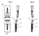
- Fig. 7-9 show the - known per se - cutting process and removing the insulation pieces 9 from the cable wires 8 to expose the conductor.
Landscapes
- Removal Of Insulation Or Armoring From Wires Or Cables (AREA)
Claims (13)
- Dispositif de dénudage des câbles multiconducteurs (2), qui s'étendent axialement, comprenant un dispositif de serrage, au moins deux couteaux (7) non-rotatifs, agissants l'un contre l'autre et au moins deux mâchoires (6) agissantes l'une contre l'autre et situées dans une distance axiale des couteaux (7), caractérisé en ce, que les mâchoires (6) peuvent être déplacée en direction vers les conducteurs de câble (8) relativement l'une à l'autre, et ainsi vers le câble (2), que la distance axiale est fixe, et qu'en condition d'opération un mouvement relative axiale du câble (2) entre le dispositif de serrage et les mâchoires (6) d'une manière d'un mouvement effleurant amène les conducteurs du câble de ses positions torsadés ou non-parallèles dans un seul plan.
- Dispositif de dénudage selon la revendication 1, caractérisé en ce, que les mâchoires (6) sont chargées par ressort en direction vers les conducteurs de câble (8).
- Dispositif de dénudage selon la revendication 1 ou 2, caractérisé en ce, que les mâchoires (6) sont appuyées relativement aux couteaux (7) ou relativement aux portes-lames, qui reçoivent les couteaux, et/ou sont supportées par les couteaux (7) ou des portes-lames de lesquels.
- Pair des couteaux (7) pour un dispositif de dénudage selon une des revendications précédentes, caractérisé en ce, que chaque couteau (7) comprend une glissière de guidage, qui guide chacune une mâchoire (6) en direction vers les conducteurs de câble (8), de manière que les mâchoires (6) sont déplaçable l'une contre l'autre et vers un câble (2) en permettant en condition d'opération un mouvement relatif axial entre le câble (2) et les mâchoires (6) ou les couteaux (7), pendant lequel les mâchoires amènent les conducteurs de câble d'une manière d'un mouvement effleurant le long de l'axe de câble de ses positions torsadés ou non-parallèles dans un seul plan.
- Couteau selon la revendication 4, caractérisé en ce, que la mâchoire (6) est supportée élastiquement par rapport au couteau (7).
- Dispositif de dénudage ou couteau selon une des revendications précédentes, caractérisé en ce, que la surface de mâchoire tournée aux conducteurs de câble (8), en position de repos, est plus proche aux conducteurs de câble (8) que l'arête coupante (10) du couteau (7).
- Couteau (7) selon la revendication 4 ou 5 ou couteau pour un dispositif de dénudage selon une des revendications 1 à 3, caractérisé en ce, qu'il est formé comme poinçon de forme, qui comprend des arêtes partiels semi-circulaires formés en correspondance avec l'épaisse de l'isolation des conducteurs (9) et situés l'un près de l'autre, le nombre desquels correspondant au moins au nombre des conducteurs de câble 8 à dénuder.
- Procédé pour dénuder d'un câble multiconducteur (2) ayant au moins deux conducteurs de câble (8), chacun ayant au moins une isolation de conducteur (9) et une gaine de câble (5), dans lequel le câble (2) est arrêté d'un dispositif de serrage, et dans lequel l'isolation de conducteur (9) est incise et enlevées par des couteaux (7) non-rotatifs après l'enlèvement de la gaine de câble (5), les conducteurs de câble (8) étant orientés en parallèle l'un à l'autre avant l'incision par les couteaux (7) d'une manière mécanique par un mouvement effleurant entre le câble et une composante capable à effleurer (6), de manière qu'ils sont amenés dans un seul plan parallèle à l'arête (1) des couteaux (7), caractérisé en ce, que la distance axiale entre la composante capable à effleurer (6) et les couteaux (7) est constante ou est maintenue constante.
- Procédé selon la revendication 8, caractérisé en ce, que le mouvement effleurant est produit par un déplacement relative des couteaux (7) et/ou des mâchoires (6) par rapport au dispositif de serrage le long des conducteurs de câble (8), en serrant simultanément lentement et pas à pas les couteaux (7) et/ou les mâchoires (6) vers les conducteurs de câble (8), préférablement en évitant une incision prématurée.
- Procédé selon la revendication 8 ou 9, caractérisé en ce, que l'on prévoit des mâchoires (6) spécifiques pour la réalisation du mouvement effleurant, qui agissent l'une contre l'autre et en direction vers les conducteurs de câble (8), et qui réalisent un mouvement relative au dispositif de serrage le long des conducteurs de câble (8), soit il indépendamment, soit il en commun avec les couteaux (7), en se déplaçant simultanément l'une relativement à l'autre.
- Procédé selon la revendication 10, caractérisé en ce, que les mâchoires (6) sont chargées par ressort en direction de serrage.
- Procédé selon la revendication 11, caractérisé en ce, que les mâchoires (6) sont chacune supportée par un couteau (7) et sont chacune appuyée élastiquement par rapport à celui-ci, la surface de mâchoire tournée aux conducteurs de câble (8), en position de repos, étant plus proche aux conducteurs de câble (8) que l'arête coupante (10) du couteau (7) respectivement adjoint.
- Procédé selon une des revendications 8 à 11, caractérisé en ce, que chaque mâchoire (6) est tenue élastiquement dans un guidage propre au même porte-outil, qui porte aussi le couteau respectivement adjoint ou le porte-lames adjoint, la force de ressort étant préférablement choisi d'une manière, que les isolations des conducteurs ne sont pas déformées substantiellement pendant l'opération effleurante.
Applications Claiming Priority (5)
| Application Number | Priority Date | Filing Date | Title |
|---|---|---|---|
| CH81198 | 1998-04-06 | ||
| CH81198 | 1998-04-06 | ||
| CH12999 | 1998-12-24 | ||
| CH12999 | 1998-12-24 | ||
| PCT/IB1999/000561 WO1999052188A1 (fr) | 1998-04-06 | 1999-04-01 | Dispositif et procede de denudage |
Publications (2)
| Publication Number | Publication Date |
|---|---|
| EP1070374A1 EP1070374A1 (fr) | 2001-01-24 |
| EP1070374B1 true EP1070374B1 (fr) | 2002-03-06 |
Family
ID=25683610
Family Applications (1)
| Application Number | Title | Priority Date | Filing Date |
|---|---|---|---|
| EP99909133A Expired - Lifetime EP1070374B1 (fr) | 1998-04-06 | 1999-04-01 | Dispositif et procede de denudage |
Country Status (5)
| Country | Link |
|---|---|
| EP (1) | EP1070374B1 (fr) |
| JP (1) | JP2002510955A (fr) |
| KR (1) | KR100696990B1 (fr) |
| DE (1) | DE59900937D1 (fr) |
| WO (1) | WO1999052188A1 (fr) |
Cited By (3)
| Publication number | Priority date | Publication date | Assignee | Title |
|---|---|---|---|---|
| US7681476B2 (en) | 2007-07-31 | 2010-03-23 | Adc Telecommunications, Inc. | Fiber optic cable stripper |
| US8640329B2 (en) | 2008-09-03 | 2014-02-04 | Adc Telecommunications, Inc. | Hybrid fiber/copper cable preparation tool |
| US11513290B2 (en) | 2019-08-30 | 2022-11-29 | Commscope Technologies Llc | Strip stop mechanism using rotating lever as a positioning stop |
Families Citing this family (7)
| Publication number | Priority date | Publication date | Assignee | Title |
|---|---|---|---|---|
| EP1231692B1 (fr) * | 2001-02-13 | 2005-07-13 | Komax Holding Ag | Dispositif pour dénuder un câble multibrin |
| KR200447181Y1 (ko) * | 2007-06-18 | 2010-01-06 | (주)어플리컴 | 전선 피복 제거기 |
| ITVI20070296A1 (it) * | 2007-11-13 | 2009-05-14 | Samec Macchine S R L | Metodo perfezionato di troncatura e sguainatura di cavi elettrici e troncatrice-sguainatrice perfezionata che realizza tale metodo |
| JP2017147846A (ja) * | 2016-02-17 | 2017-08-24 | 住友電装株式会社 | 電線加工装置、及び電線加工用刃 |
| EP3739702A1 (fr) | 2019-05-16 | 2020-11-18 | Komax Holding Ag | Procédé d'enlèvement d'une isolation des conducteurs intérieurs d'un câble et dispositif de dénudation |
| JP7307130B2 (ja) * | 2021-09-06 | 2023-07-11 | 矢崎総業株式会社 | シールド箔の除去方法およびシールド箔の除去装置 |
| CN114649120A (zh) * | 2022-03-21 | 2022-06-21 | 浙江万马股份有限公司 | 一种交联电缆快速剥线装置及其剥线方法 |
Family Cites Families (2)
| Publication number | Priority date | Publication date | Assignee | Title |
|---|---|---|---|---|
| US4170906A (en) * | 1977-10-31 | 1979-10-16 | Northern Telecom Limited | Wire skinning machine |
| DE3329491C1 (de) * | 1983-08-16 | 1985-03-21 | Stocko Metallwarenfabriken Henkels Und Sohn Gmbh & Co, 5600 Wuppertal | Verfahren und Vorrichtung zum Ablängen und Abisolieren von Mehrfachleitern |
-
1999
- 1999-04-01 DE DE59900937T patent/DE59900937D1/de not_active Expired - Lifetime
- 1999-04-01 KR KR1020007011070A patent/KR100696990B1/ko not_active IP Right Cessation
- 1999-04-01 WO PCT/IB1999/000561 patent/WO1999052188A1/fr active IP Right Grant
- 1999-04-01 EP EP99909133A patent/EP1070374B1/fr not_active Expired - Lifetime
- 1999-04-01 JP JP2000542836A patent/JP2002510955A/ja active Pending
Cited By (3)
| Publication number | Priority date | Publication date | Assignee | Title |
|---|---|---|---|---|
| US7681476B2 (en) | 2007-07-31 | 2010-03-23 | Adc Telecommunications, Inc. | Fiber optic cable stripper |
| US8640329B2 (en) | 2008-09-03 | 2014-02-04 | Adc Telecommunications, Inc. | Hybrid fiber/copper cable preparation tool |
| US11513290B2 (en) | 2019-08-30 | 2022-11-29 | Commscope Technologies Llc | Strip stop mechanism using rotating lever as a positioning stop |
Also Published As
| Publication number | Publication date |
|---|---|
| KR20010034744A (ko) | 2001-04-25 |
| KR100696990B1 (ko) | 2007-03-20 |
| WO1999052188A1 (fr) | 1999-10-14 |
| JP2002510955A (ja) | 2002-04-09 |
| DE59900937D1 (de) | 2002-04-11 |
| EP1070374A1 (fr) | 2001-01-24 |
Similar Documents
| Publication | Publication Date | Title |
|---|---|---|
| DE68920497T2 (de) | Apparat zum stufenweisen Abisolieren von Draht. | |
| DE69704236T2 (de) | Hautaufnehmende Vorrichtung zum Entnehmen des Anus | |
| EP2919340B1 (fr) | Procédé de détermination de paramètres de dénudage pour dénuder un câble | |
| EP1070374B1 (fr) | Dispositif et procede de denudage | |
| DE112017004840T5 (de) | Rotative Abisoliervorrichtung | |
| DE3922437A1 (de) | Drahtbearbeitungsvorrichtung | |
| EP1273939A2 (fr) | Méthode et pince pour couper des câbles à fibres optiques amorphes | |
| DE4238774B4 (de) | Verfahren und Vorrichtung zum Durchtrennen einer Kabelummantelung aus Fasern | |
| EP0021090B1 (fr) | Appareil pour le découpage de plusieurs fibres optiques réunies dans un câble | |
| EP3309915B1 (fr) | Pince à dénuder, couteau à dénuder, et procédé de dénudage | |
| DE2531844C3 (de) | Vorrichtung zum Durchschneiden und Abisolieren eines mehrdrähtigen Leiters | |
| WO2015162118A1 (fr) | Procédé et dispositif de séparation d'une partie librement isolée d'un blindage | |
| DE202008017747U1 (de) | Vorrichtung zum Entfernen einer Mantelschicht von drahtähnlichen Elementen | |
| EP3713023A1 (fr) | Dispositif ainsi que procédé d'isolation | |
| EP1515410A2 (fr) | Tête porte-lames pour appareil de traitement de câble | |
| EP0430868A1 (fr) | Procédé et dispositif pour dénuder les extrémités de câbles optiques | |
| DE3335483A1 (de) | Verfahren und vorrichtung zur entfernung der aeusseren isolierung ein- oder mehradriger kabel | |
| DE202008017576U1 (de) | Bearbeitungsmodul für eine Kabelabisoliervorrichtung | |
| DE19910260B4 (de) | Vorrichtung zur Bearbeitung eines Endes eines Werkstücks | |
| EP1304927B1 (fr) | Dispositif de support d'outil de coupe | |
| DE718669C (de) | Einrichtung zum Entisolieren von elektrischen Leitungsdraehten | |
| DE3025712C2 (de) | Verfahren und Vorrichtung zum Ablösen eines Streifens aus einem Metallblech-Wickelkörper | |
| DE2804858C2 (de) | Vorrichtung zum Entfernen der an den Anodennippeln von Anodenstangen angeordneten Gußhülsen | |
| DE10209181B4 (de) | Verfahren und Zange zum Abisolieren von Leiterenden | |
| DE10323495B3 (de) | Verfahren und Vorrichtung zum Abisolieren von Flachbandleitern |
Legal Events
| Date | Code | Title | Description |
|---|---|---|---|
| PUAI | Public reference made under article 153(3) epc to a published international application that has entered the european phase |
Free format text: ORIGINAL CODE: 0009012 |
|
| 17P | Request for examination filed |
Effective date: 20001106 |
|
| AK | Designated contracting states |
Kind code of ref document: A1 Designated state(s): CH DE FR GB IT LI |
|
| GRAG | Despatch of communication of intention to grant |
Free format text: ORIGINAL CODE: EPIDOS AGRA |
|
| 17Q | First examination report despatched |
Effective date: 20010425 |
|
| GRAG | Despatch of communication of intention to grant |
Free format text: ORIGINAL CODE: EPIDOS AGRA |
|
| GRAH | Despatch of communication of intention to grant a patent |
Free format text: ORIGINAL CODE: EPIDOS IGRA |
|
| GRAH | Despatch of communication of intention to grant a patent |
Free format text: ORIGINAL CODE: EPIDOS IGRA |
|
| REG | Reference to a national code |
Ref country code: GB Ref legal event code: IF02 |
|
| GRAA | (expected) grant |
Free format text: ORIGINAL CODE: 0009210 |
|
| AK | Designated contracting states |
Kind code of ref document: B1 Designated state(s): CH DE FR GB IT LI |
|
| REG | Reference to a national code |
Ref country code: CH Ref legal event code: EP |
|
| REF | Corresponds to: |
Ref document number: 59900937 Country of ref document: DE Date of ref document: 20020411 |
|
| GBT | Gb: translation of ep patent filed (gb section 77(6)(a)/1977) |
Effective date: 20020530 |
|
| ET | Fr: translation filed | ||
| PLBQ | Unpublished change to opponent data |
Free format text: ORIGINAL CODE: EPIDOS OPPO |
|
| PLBI | Opposition filed |
Free format text: ORIGINAL CODE: 0009260 |
|
| PLBF | Reply of patent proprietor to notice(s) of opposition |
Free format text: ORIGINAL CODE: EPIDOS OBSO |
|
| 26 | Opposition filed |
Opponent name: SAMEC DIVISIONE COSTRUZIONE MACCHINE SRL Effective date: 20021204 |
|
| PLBF | Reply of patent proprietor to notice(s) of opposition |
Free format text: ORIGINAL CODE: EPIDOS OBSO |
|
| PLBP | Opposition withdrawn |
Free format text: ORIGINAL CODE: 0009264 |
|
| PLBL | Opposition procedure terminated |
Free format text: ORIGINAL CODE: EPIDOS OPPC |
|
| REG | Reference to a national code |
Ref country code: CH Ref legal event code: NV Representative=s name: PATENTBUERO PAUL ROSENICH AG |
|
| PLBM | Termination of opposition procedure: date of legal effect published |
Free format text: ORIGINAL CODE: 0009276 |
|
| STAA | Information on the status of an ep patent application or granted ep patent |
Free format text: STATUS: OPPOSITION PROCEDURE CLOSED |
|
| 27C | Opposition proceedings terminated |
Effective date: 20030403 |
|
| PGFP | Annual fee paid to national office [announced via postgrant information from national office to epo] |
Ref country code: GB Payment date: 20050321 Year of fee payment: 7 |
|
| PG25 | Lapsed in a contracting state [announced via postgrant information from national office to epo] |
Ref country code: GB Free format text: LAPSE BECAUSE OF NON-PAYMENT OF DUE FEES Effective date: 20060401 |
|
| PGFP | Annual fee paid to national office [announced via postgrant information from national office to epo] |
Ref country code: FR Payment date: 20060418 Year of fee payment: 8 |
|
| PGFP | Annual fee paid to national office [announced via postgrant information from national office to epo] |
Ref country code: IT Payment date: 20060430 Year of fee payment: 8 |
|
| GBPC | Gb: european patent ceased through non-payment of renewal fee |
Effective date: 20060401 |
|
| PG25 | Lapsed in a contracting state [announced via postgrant information from national office to epo] |
Ref country code: FR Free format text: LAPSE BECAUSE OF NON-PAYMENT OF DUE FEES Effective date: 20070430 |
|
| PG25 | Lapsed in a contracting state [announced via postgrant information from national office to epo] |
Ref country code: IT Free format text: LAPSE BECAUSE OF NON-PAYMENT OF DUE FEES Effective date: 20070401 |
|
| PGFP | Annual fee paid to national office [announced via postgrant information from national office to epo] |
Ref country code: CH Payment date: 20170306 Year of fee payment: 19 |
|
| PGFP | Annual fee paid to national office [announced via postgrant information from national office to epo] |
Ref country code: DE Payment date: 20170430 Year of fee payment: 19 |
|
| REG | Reference to a national code |
Ref country code: DE Ref legal event code: R082 Ref document number: 59900937 Country of ref document: DE |
|
| REG | Reference to a national code |
Ref country code: DE Ref legal event code: R119 Ref document number: 59900937 Country of ref document: DE |
|
| REG | Reference to a national code |
Ref country code: CH Ref legal event code: PL |
|
| PG25 | Lapsed in a contracting state [announced via postgrant information from national office to epo] |
Ref country code: DE Free format text: LAPSE BECAUSE OF NON-PAYMENT OF DUE FEES Effective date: 20181101 |
|
| PG25 | Lapsed in a contracting state [announced via postgrant information from national office to epo] |
Ref country code: LI Free format text: LAPSE BECAUSE OF NON-PAYMENT OF DUE FEES Effective date: 20180430 Ref country code: CH Free format text: LAPSE BECAUSE OF NON-PAYMENT OF DUE FEES Effective date: 20180430 |