EP3713023A1 - Dispositif ainsi que procédé d'isolation - Google Patents
Dispositif ainsi que procédé d'isolation Download PDFInfo
- Publication number
- EP3713023A1 EP3713023A1 EP20163863.2A EP20163863A EP3713023A1 EP 3713023 A1 EP3713023 A1 EP 3713023A1 EP 20163863 A EP20163863 A EP 20163863A EP 3713023 A1 EP3713023 A1 EP 3713023A1
- Authority
- EP
- European Patent Office
- Prior art keywords
- stripping
- cable
- knife
- knife device
- insulation
- Prior art date
- Legal status (The legal status is an assumption and is not a legal conclusion. Google has not performed a legal analysis and makes no representation as to the accuracy of the status listed.)
- Pending
Links
Images


Classifications
-
- H—ELECTRICITY
- H02—GENERATION; CONVERSION OR DISTRIBUTION OF ELECTRIC POWER
- H02G—INSTALLATION OF ELECTRIC CABLES OR LINES, OR OF COMBINED OPTICAL AND ELECTRIC CABLES OR LINES
- H02G1/00—Methods or apparatus specially adapted for installing, maintaining, repairing or dismantling electric cables or lines
- H02G1/12—Methods or apparatus specially adapted for installing, maintaining, repairing or dismantling electric cables or lines for removing insulation or armouring from cables, e.g. from the end thereof
- H02G1/1202—Methods or apparatus specially adapted for installing, maintaining, repairing or dismantling electric cables or lines for removing insulation or armouring from cables, e.g. from the end thereof by cutting and withdrawing insulation
- H02G1/1248—Machines
- H02G1/1251—Machines the cutting element not rotating about the wire or cable
- H02G1/1253—Machines the cutting element not rotating about the wire or cable making a transverse cut
- H02G1/1256—Machines the cutting element not rotating about the wire or cable making a transverse cut using wire or cable-clamping means
Definitions
- the invention relates to a stripping device which is suitable for stripping a cable.
- the invention also relates to a method.
- the JP H07 236214 A for example contains a defect detector which detects a possible contact of a pair of knives with the cable strands.
- the two knives of a pair of knives of the stripping device are moved towards one another and pressed through the insulation.
- the pair of knives is then moved in a direction opposite to this feed movement, the two knives of the pair of knives, however, remaining in contact with the cable jacket.
- an evaluation unit on the stripping knife device a possible contact of the knife or a knife with the cable strands is detected.
- the stripping knife device can have electrical insulation of the pair of knives.
- the pair of knives is moved in a direction parallel to the longitudinal direction of the cable in order to strip off the cable insulation.
- this damaged cable has a cable core that differs in diameter or diameter from those that remained undamaged during stripping.
- zero cut knives are also known to determine the position of the cable end by cutting off the excess cable for possible subsequent processes and to trim the cable end with a defined cut from any protruding or recessed insulation or protruding or recessed individual strands.
- the invention aims to provide a stripping device with a stripping knife device and a contacting device with which a cable can be processed with high quality.
- One idea of the invention is to combine a contacting device, in the present embodiment as a zero cut knife device, and a stripping knife device in a stripping device in order to carry out a stripping process.
- the invention relates to a device for improving the stripping process of a stripping knife device, so that a cable end can be stripped without damage.
- the invention provides a stripping device for stripping a cable insulation with a stripping knife device and a zero cut knife device.
- the two knife devices can be moved independently of one another. As a result, the stripping process of a cable can be carried out without damage.
- the zero cut knife device can be used for additional functions.
- the zero cut of the zero cut knife device can also be divided into several stages. At the beginning of the stripping process, the zero cut knife device can penetrate the insulation and touch the strands, so that contact is established between the zero cut knife device and the cable strand. The stripping knife device can then cut into the insulation, making contact with the cable strand is avoided, an unwanted contact between the stripping knife device and the cable strands being detected.
- the two knife devices are attached electrically insulated from one another and can therefore have different electrical potentials.
- a detection by the evaluation device is provided on one of the knife devices. Detection can thus be carried out on the evaluation device by the stripping knife device and / or zero cut knife device. Consequently, it can be ensured that the stripping knife device of the stripping device does not cut too deeply into the insulation, since otherwise contacting is detected.
- the evaluation unit can detect the contact on the basis of a voltage measurement.
- the independent movement between the stripping knife device and the zero cut knife device takes place in the preferred embodiment via an additional process axis.
- the stripping device has a variable distance between the stripping knife device and zero cut knife device, whereby a predetermined length of the cable to be stripped can be maintained and, in one possible embodiment, the stripping length can be varied by adjusting the distance between the stripping knife device and / or zero cut knife device.
- Possible further processing steps for the stripped cable are, for example, crimping. Therefore the stripped cable strands must be free from damage in order to maintain the high quality of the cable.
- the stripping device has a suction device or blow-off device in order to remove the severed zero cut and the stripped insulation from the stripping device. This means that the insulation can be stripped easily and safely.
- a preferred embodiment comprises a cable gripper which guides the cable in the direction of the knife device or in the opposite direction.
- the cable gripper also has the function of fixing the cable during the stripping process.
- the cable gripper can fix the cable while the stripping is being pulled off by the stripping device.
- the gripper device is provided on the stripping device, as a result of which the insulation can be removed. This means that the insulation can be stripped easily and safely.
- the stripping device is preferably configured in such a way that various methods for stripping insulation from a cable can be implemented.
- the removal process is carried out by the contacting device, in the preferred embodiment designed as a zero-cut knife device. Due to the independent movement of the knife pairs and the variable distance between the stripping knife device and zero-cut knife device, the zero-cut knife device can be moved in the direction of the stripping knife device and the pulling process, as a partial step of the stripping process, can be performed by the zero-cut knife device. So can the pulling process can be carried out easily and safely by the zero cut knife device.
- a further embodiment comprises a stripping knife device, zero cut knife device and a gripper device, the gripper device carrying out the pulling process or part of the pulling movement of the severed cable insulation.
- the gripper device is attached to the independently movable zero-cut knife device and is controlled by the movement of the zero-cut knife device.
- the gripper device can, for example, be configured in an independent station. The gripper device has the advantage that the cable strand is not damaged by a suitable geometry and choice of material.
- a stripping process can be carried out by the stripping knife device and in combination with the cable gripper. This means that the insulation can be stripped easily and safely.
- the stripping knife device performs the zero cut.
- the contacting device of a further embodiment can have a blunt geometry.
- the zero cut is only made after the stripping process. It can be provided that the functions and tasks of the zero cut knife device are taken over by the stripping knife device.
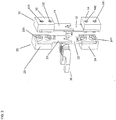
- FIG. 1 shows a stripping device of a first embodiment, the devices thereof with reference to FIG Figure 1-4F is described in more detail.
- the stripping device 100 is designed to remove insulation from a cable 40 and includes a stripping knife device 20 and a contacting device, in the present embodiment designed as a zero cut knife device 10, which are characterized in that the stripping knife device 20 and the zero cut knife device 10 are independent of one another are movable. This ensures that the stripping knife device 20 can be moved and controlled independently of the zero cut knife device 10. In a preferred embodiment, the zero cut knife device 10 and the stripping knife device 20 are moved by separate electromechanical drive units 70, 80.
- the stripping knife device 20 contains a first pair of knives 21, 22, each knife being attached to a respective holder 23, 24. According to a modification, the stripping knife device can consist of a plurality of knives and knife pairs.
- a pair of knives has two knives, a first knife 21 which is attached to a first holder 23, and a second knife 22 which is attached to a second holder 24.
- Each knife is attached to the holder with two screws 231, 232, 242, 241, the number of screws and knives not being set to two, and other fastening means can also be used.
- the two knives 21, 22 are provided essentially mirror images of one another.
- the knives are made of a conductive material (for example a metal).
- the two knives 21, 22 have, for example, a V-shaped cutting edge.
- the cutting edge on the respective knife 21, 22 is provided in the direction of the cable, with the function that the two knives, when moving towards one another, press the cutting edge into the cable insulation 42 of a cable 40 and cut it.
- the two knives 21, 22 of the stripping knife device move past one another, for example when moving towards one another, the distance in the horizontal direction being selected to be very small, so that a reliable severing of the cable insulation is ensured.
- the respective knives or a knife 21, 22 can also be designed as a crush cut knife, shaped knife or nozzle knife or as a scissor cut knife.
- the zero cut knife device 10 contains a pair of knives 11, 12, each knife being attached to a holder 13, 14.
- the zero cut knife device can also consist of a plurality of knives.
- a pair of knives has, for example, two knives, namely a first knife 11 which is attached to a first holder 13, and a second knife 12 which is attached to a second holder 14.
- Each knife is attached to the holder with two screws 131, 132, 142, 141, the number of screws not being fixed at two, and other fastening means can also be used.
- the two knives 11, 12 are provided essentially mirror images of one another.
- the knives 11, 12 are made of a conductive material (for example a metal).
- the two Knives 11, 12 have, for example, a V-shaped cutting edge.
- the cutting edge on the respective knife 11, 12 is provided in the direction of the cable, with the function that the two knives, when moving towards one another, penetrate with the cutting edge into the cable insulation 42 of a cable 40 and cut through the cable insulation 42.
- the two knives 11, 12 of the zero cut knife device move past one another, for example, the distance in the horizontal direction being selected to be relatively small, so that a reliable severing of the cable insulation is ensured.
- the respective knives or a knife 11, 12 can also be designed as a crush cut knife, shaped knife or nozzle knife or as a scissor cut knife.
- the contacting device can, for example, have a blunt geometry.
- the knives 11, 12, 21, 22 of the stripping knife device 20 and the zero cut knife device 10 can be moved in a first direction (for example vertical direction).
- the blades can be moved towards and away from one another for stripping a cable insulation.
- the two knives 11, 12, 21, 22 of the stripping knife device and zero cut knife device move past one another, for example, when they move towards one another.
- the mutually facing side surfaces of the first and second knives 11, 12, 21, 22 are, for example, spaced apart from one another in a second direction (for example, horizontal direction) which is essentially perpendicular to the first direction. This distance ensures that the knives can, if necessary, overlap in sections without coming into engagement with one another, even if the knives are deformed when the insulation is stripped or the cable jacket is stripped off.
- one pair of knives 11, 12, 21, 22 in the stripping device 100 are fastened to the knife holder 13, 14, 23, 24 in an electrically insulated manner from the other or further pair of knives.
- the insulation, which electrically isolates the knives from the knife holders, can for example be screwed, glued or connected in some other way to the respective holder.
- the zero cut knife device 10 can be moved independently of the stripping knife device 20 through one or more additional process axes. As a result, the stripping knife device and the zero cut knife device can be moved and controlled independently of one another.
- the stripping device 100 is set up to vary the distance between the stripping knife device 20 and the zero cut knife device 10.
- the zero cut knife device 10 is configured to lead relative to the stripping knife device 20.
- the stripping knife device 20 is attached between the cable gripper and the zero cut knife device 10.
- a variable distance between the zero cut knife device and the stripping knife device also makes it possible to change the distance before, during, and after the stripping process.
- the stripping knife device 20 and / or the zero cut knife device 10 is connected to an evaluation unit.
- the evaluation unit is connected to the stripping knife device 20 and / or to the zero cut knife device 10, and so on configured that signals can be transmitted. These signals can be electrical current or electrical voltage, for example.
- the stripping device 100 comprises a suction device 60 which is configured for suctioning off a severed insulation 42 and / or the zero cut.
- the suction device 60 removes a loose cable insulation 42, which occurs during the stripping process, so that no stripping residues collect in the stripping device. Waste disposal can also be carried out with blowing, in order to blow away the cable insulation 42 or the zero cut, that is to say the stripping residues.
- the stripping device 100 contains a cable gripper 30, which guides the cable in the direction of the knife device or in the opposite direction.
- the cable gripper introduces the cable into the stripping knife device and zero cut knife device, and is therefore attached to the stripping knife device in the first place in relation to the zero cut knife device (see also Figure 2 ).
- the stripping device 100 comprises the stripping knife device 20, the zero cut knife device 10, the cable gripper 30, the suction device 60 and the evaluation unit as in FIG Figure 1 shown.
- the zero cut knife device 10 is attached in an electrically insulated manner from the stripping knife device 20, and the zero cut knife device 10 is leading relative to the stripping knife device 20.
- the stripping device 100 is equipped so that the stripping process can be carried out by the zero cut knife device 20 (see also FIG Figures 3A-3F , Figures 4A-4F ).
- the stripping length is the length of the cable which is limited by the stripping knife device and zero cut knife device in the second direction (for example horizontally) and at the same time the length over which the cable insulation of the cable is removed.
- the stripping device cuts in by moving the knives 21, 22 towards each other to the stripping depth, which describes the depth at which only the cable insulation 42 is cut with the cutting edges of the knives 21, 22 ( Figure 3 C) .
- a detection process takes place on the evaluation unit.
- a continuity measurement is used to check whether the stripping knife device has cut through the cable sheath and whether the cable strand has been touched in addition to the cable jacket 42 and whether there is contact with the strand at the cutting edge of the knife 21, 22 ( Figure 3 D) .
- a potential difference between the knife pairs 11, 12, 21, 22 can be detected through the contact. If a contact is established on the evaluation unit via the detection process, damage to the cable strand 41 of the cable 40 cannot be ruled out. The damaged cable can therefore be sorted out, depending on the processing requirements.
- an electrically conductive stripping knife device 20 (stripping knife edge) and the mechanical contact of an electrically conductive contacting device 10, e.g. Cutting edge of the zero cut knife device, with one or more cable strands
- the two devices are connected to one another in a low-resistance and thus electrically conductive manner by the electrically conductive cable strands.
- the two devices were electrically insulated from one another with high resistance and thus electrically separated.
- the change in electrical resistance which functions similarly to that of an electrical closing contact, can be detected by the evaluation unit in the function of electrical continuity detection.
- a return stroke of the stripping knife device ( Figure 3 E) .
- a return stroke denotes a slight opening of the two knives 21, 22 of the stripping knife device, but contact between the knives 21, 22 and the cable insulation 42 remains.
- the detection device is not switched off and any possible further contact between the stripping knife device and the stranded wire during the process is also checked.
- the zero cut knife device completely cuts through the cable 40, consisting of the cable insulation 42 and cable strand 41 ( Figure 3 E) .
- the zero cut knife device ( Figure 3 F) in which the first knife 11 and the second knife 12 are moved in opposite directions.
- the complete severing of the cable 40 to the stripping length by the zero cut knife device 10 is called a zero cut designated.
- the cable section 40 cut off by the zero cut knife device is then removed, for example, by the suction device 60, so that the cut cable section cannot interfere with or hinder the stripping process.
- step Figure 3 F the zero cut knife device has cut through the cable insulation 42 and the cable strand 41 and the stripping knife device has cut the cable insulation 42 so that the cable insulation 42 is still around the cable strand 41.
- the knives 11, 12 of the zero-cut knife device 10 open by moving in the opposite direction.
- the pulling process is carried out by the zero cut knife device 10 ( Figures 4A-4F ). Due to the variable distance between the stripping knife device and zero-cut knife device, the zero-cut knife device is moved in the direction of the stripping knife device for the stripping process in a direction parallel to the longitudinal direction of the cable, starting from the last step Figure 3 F , offset ( Figure 4 A) . In the next step ( Figure 4 B, C ) the zero cut knife device cuts into the cable insulation section that has already been severed, but not in contact with the cable braid 41. Then the stripping knife device opens and the two knives 21, 22 are guided in the opposite direction ( Figure 4 D) .
- the removal movement of the zero cut knife device takes place by increasing the distance to the stripping knife device in a direction parallel to the longitudinal direction of the cable 40 ( Figure 4 E) , while the evaluation unit continues to perform a detection process.
- the two knives 11, 12 of the zero cut knife device pull the insulation off the cable strand 41 of the cable 40 with a slight contact with the cable insulation 42 by a movement that increases the distance between the stripping knife device and the zero cut knife device.
- the zero cut knife device 10 opens again in that both knives 11, 12 move in opposite directions. Any cable insulation that may be stuck can be stripped off by the opening movement.
- the severed cable insulation 42 can be removed from the stripping device 100, for example by the suction device 60 ( Figure 4 F) .
- the stripping device 100 contains a gripper device 50 for pulling off the insulation.
- the gripper device can be attached to the zero cut knife device so that the gripper device moves with the zero cut knife device, or the gripper device is configured as an independent unit, for example as an independent station, in the stripping device 100.
- the gripper device is equipped so that the cable insulation is pulled off or separated from the cable strand by the gripper device.
- the geometry and structure of the gripper device can be selected in such a way that damage to the cable strands 41 is prevented.
- the Gripper device consist of a polymer and / or metallic components.
- the stripping device 100 comprises, similar to the first embodiment, the stripping knife device 20, the zero cut knife device 10, the cable gripper 30, the suction device 60, the evaluation unit.
- the zero cut knife device 10 is attached in an electrically insulated manner from the stripping knife device 20, and the zero cut knife device 10 is leading relative to the stripping knife device 20.
- the zero cut knife device is equipped in the second embodiment so that the pulling process can be carried out by the gripper device configured on the zero cut knife device ( Figures 5A-5F ).
- the gripper device can also be configured independently of the zero cut knife device.
- the second embodiment of the stripping device 100 comprises the stripping knife device 20, the zero cut knife device 10 and a gripper device 50, the gripper device performing the stripping process.
- the gripper device 50 is attached to the zero cut knife device.
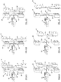
- the upper half of the gripper device 51 moves in the same direction with the first knife of the zero cut knife device 11 and the first knife holder 13 of the zero cut knife device 10.
- the step in Figure 5 A exhibits the step Figure 3 F in the second embodiment with the gripper device repetitive.
- the sequence of Figures 5A-5F is therefore off with the sequence Figures 3A-3F combinable.
- the zero cut knife device 10 and the gripper device 50 move simultaneously in the direction of the stripping knife device 20 in a direction parallel to the longitudinal direction of the cable.
- the knives 11, 12 of the zero cut knife device close until the two halves of the gripper device 51, 52 come into contact with the cable insulation 42 ( Figure 5 C) .
- the two knives of the stripping knife device 21, 22 open by moving in the opposite direction and move away from the cable ( Figure 5 D) . This means that the cable and the cable insulation are no longer held in place by the stripping knife device.
- the zero cut knife device and the gripper device move together in the opposite direction, a direction parallel to the longitudinal direction of the cable 40, in order to increase the distance from the stripping knife device ( Figure 5 E) .
- the cable insulation 42 is now pulled over the contact between the gripper device 50 and the cable insulation 42 from the cable 40 and the cable strand 41 (pulling process).
- the zero cut knife device opens again together with the gripper device and thus increases the distance between the two knives 11, 12 and the two halves of the gripper device 51, 52 ( Figure 5 F) .
- the separated cable insulation 42 is loose and can, for example can be removed from the stripping device 100 by the suction device 60.
- the gripper device cannot be configured on the zero cut knife device and can be moved independently. In this case, the cable insulation 42 is pulled off by the gripper device 50, so that the stripped insulation is stripped off the cable strand 41.
- the gripper device can be configured downstream as an independent process.
- the stripping device 100 comprises the stripping knife device 20, the zero cut knife device 10, the cable gripper 30, the suction device 60, and the evaluation unit.
- the zero cut knife device 10 is attached electrically insulated from the stripping knife device 20, and the zero cut knife device 10 is leading relative to the stripping knife device 20.
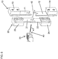
- the stripping device 100 is equipped so that the stripping process can be carried out by the stripping knife device 20 ( Figure 6 ).
- the stripping device 100 comprises a stripping knife device 20 and a zero cut knife device 10, the cable gripper 30, the suction device 60 and the evaluation unit as in FIG Figure 1 shown, wherein the stripping process is carried out by the stripping knife device 20.
- the process of the third embodiment starts again from the last step of FIG Figure 3F and the expiration of Figure 6 is with the expiration in Figures 3A-3F combinable.
- the knives of the stripping knife device 21, 22 open slightly in the opposite direction by a return stroke, so that the two knives of the pair of stripping knives 21, 22 only have one contact with the cable insulation 42.
- the stripping knife device moves, the knives 21, 22 of the stripping knife device only in contact with the cable insulation 42, at the same time away from the cable and the cable gripper 30, in a direction parallel to the longitudinal direction of the cable, in order to increase the distance between the cable gripper and the stripping knife device enlarge.
- the cable insulation 42 is stripped from the cable 40 and the cable strand 41.
- the loose cable insulation can now be removed from the stripping device 100 by the suction device 60, for example.
- the cable gripper 40 removes the cable after step Figure 3 F and the return stroke of the stripping knife device 20, in the opposite movement, and thus increases the distance between the cable gripper 40 and the stripping knife device. As a result of this opposite movement of the cable gripper, the cable insulation 42 is stripped from the cable 40 and the cable strand 41 on the knives of the stripping knife device 20.
- stripping process is the stripping by the stripping knife device 20 (not shown), which after the step in FIG Figure 3 F , the knife of the stripping knife device opens and the stripping knife device parallel, in the direction of the Zero cut knife device offset.
- the stripping knife device then cuts slightly into the severed cable insulation 42 and, by moving the stripping knife device and zero cut knife device in one direction, with an increase in the distance to the severed cable insulation, parallel to the longitudinal direction of the cable, pulls the cable insulation 42 off the cable 40 and the cable strand 41.
- the stripping length of the cable insulation 42 can be adjusted by increasing or decreasing the distance between the stripping knife device 20 and the zero cut knife device 10, in a direction parallel to the longitudinal direction of the cable 40.
- different stripping lengths can be carried out in the stripping device 100.
- the stripping process can be carried out by the stripping knife device and the contacting device in such a way that the stripping knife device performs the zero cut.
- the contacting device can only establish electrical contact with the stranded cable and / or not cut into the cable.
- the zero cut can be made by the stripping knife device or the contacting unit after the cable insulation 42 has been stripped from the cable 40 and the cable strand 41.
- the stripping knife device can take over all the functions and steps of the zero cut knife device, so that the stripping device 100 can be manufactured more cost-effectively.
- V-shaped cutting edges of the knives 21, 22, 11, 12 are described above, the cutting edge can according to FIG other embodiments also have a different configuration.
- the respective knives or a knife 11, 12, 21, 22 can be designed as a squeeze knife, shaped knife or nozzle knife. Since the pairs of knives of such a knife device do not overlap when the insulation is cut, contact between the knives can be avoided.
Applications Claiming Priority (1)
| Application Number | Priority Date | Filing Date | Title |
|---|---|---|---|
| DE102019203708.9A DE102019203708A1 (de) | 2019-03-19 | 2019-03-19 | Abisoliervorrichtung sowie Verfahren |
Publications (1)
| Publication Number | Publication Date |
|---|---|
| EP3713023A1 true EP3713023A1 (fr) | 2020-09-23 |
Family
ID=69903017
Family Applications (1)
| Application Number | Title | Priority Date | Filing Date |
|---|---|---|---|
| EP20163863.2A Pending EP3713023A1 (fr) | 2019-03-19 | 2020-03-18 | Dispositif ainsi que procédé d'isolation |
Country Status (2)
| Country | Link |
|---|---|
| EP (1) | EP3713023A1 (fr) |
| DE (1) | DE102019203708A1 (fr) |
Cited By (1)
| Publication number | Priority date | Publication date | Assignee | Title |
|---|---|---|---|---|
| EP4084246A1 (fr) | 2021-04-26 | 2022-11-02 | Schäfer Werkzeug- und Sondermaschinenbau GmbH | Dispositif d'usinage de câbles |
Citations (5)
| Publication number | Priority date | Publication date | Assignee | Title |
|---|---|---|---|---|
| US3645156A (en) * | 1970-06-11 | 1972-02-29 | Gen Electric | Automatic wire nick detector for electric wire cut and strip machines |
| DE4206067A1 (de) * | 1991-02-28 | 1992-09-03 | Amp Inc | Kabelabisoliervorrichtung |
| JPH07236214A (ja) | 1994-02-22 | 1995-09-05 | Fujikura Ltd | 芯線傷検出装置 |
| JP2001112137A (ja) * | 1999-10-01 | 2001-04-20 | Japan Automat Mach Co Ltd | 被覆電線の皮剥き方法および装置 |
| EP2919340A1 (fr) * | 2014-03-11 | 2015-09-16 | Komax Holding AG | Procédé de détermination de paramètres de dénudage pour dénuder un câble |
Family Cites Families (4)
| Publication number | Priority date | Publication date | Assignee | Title |
|---|---|---|---|---|
| DE102007053825B4 (de) * | 2007-11-12 | 2017-10-19 | Te Connectivity Germany Gmbh | Abisoliervorrichtung mit Berührungssensor und Justierhilfe für eine Abisoliervorrichtung |
| DE102009027967B4 (de) * | 2008-08-08 | 2023-06-15 | Volkswagen Ag | Verfahren und Vorrichtung zur Überwachung der Abisolierung von Leitungsenden |
| DE102011084099A1 (de) * | 2011-10-06 | 2013-04-11 | Robert Bosch Gmbh | Verfahren und Vorrichtung zum Abisolieren eines Drahtes |
| EP2717399A1 (fr) * | 2012-10-08 | 2014-04-09 | Komax Holding AG | Procédé de dénudement d'un câble |
-
2019
- 2019-03-19 DE DE102019203708.9A patent/DE102019203708A1/de active Pending
-
2020
- 2020-03-18 EP EP20163863.2A patent/EP3713023A1/fr active Pending
Patent Citations (5)
| Publication number | Priority date | Publication date | Assignee | Title |
|---|---|---|---|---|
| US3645156A (en) * | 1970-06-11 | 1972-02-29 | Gen Electric | Automatic wire nick detector for electric wire cut and strip machines |
| DE4206067A1 (de) * | 1991-02-28 | 1992-09-03 | Amp Inc | Kabelabisoliervorrichtung |
| JPH07236214A (ja) | 1994-02-22 | 1995-09-05 | Fujikura Ltd | 芯線傷検出装置 |
| JP2001112137A (ja) * | 1999-10-01 | 2001-04-20 | Japan Automat Mach Co Ltd | 被覆電線の皮剥き方法および装置 |
| EP2919340A1 (fr) * | 2014-03-11 | 2015-09-16 | Komax Holding AG | Procédé de détermination de paramètres de dénudage pour dénuder un câble |
Cited By (1)
| Publication number | Priority date | Publication date | Assignee | Title |
|---|---|---|---|---|
| EP4084246A1 (fr) | 2021-04-26 | 2022-11-02 | Schäfer Werkzeug- und Sondermaschinenbau GmbH | Dispositif d'usinage de câbles |
Also Published As
| Publication number | Publication date |
|---|---|
| DE102019203708A1 (de) | 2020-09-24 |
Similar Documents
| Publication | Publication Date | Title |
|---|---|---|
| EP3089294B1 (fr) | Dispositif d'usinage de câble et procédé destiné à éliminer une feuille de blindage d'un câble rond à plusieurs fils, blindé | |
| EP2919340B1 (fr) | Procédé de détermination de paramètres de dénudage pour dénuder un câble | |
| EP2871737B1 (fr) | Dispositif et procédé de dénudage | |
| EP2780993B1 (fr) | Détection d'une entaille sur un toron | |
| EP2871736A1 (fr) | Installation de traitement d'un câble à plusieurs fils | |
| EP2717399A1 (fr) | Procédé de dénudement d'un câble | |
| EP2980937A1 (fr) | Procédé et dispositif de fabrication d'un câble blindé et câble blindé | |
| EP3312956B1 (fr) | Procédé et dispositif pour dénuder un câble comprenant une gaine multicouches | |
| EP3236550A1 (fr) | Dispositif et procede destines a denuder un cable | |
| EP2190080A2 (fr) | Dispositif de sertissage et de dénudement d'un conducteur d'un câble à plusieurs fils | |
| DE102020103548A1 (de) | Verfahren und Vorrichtung zur Konfektionierung eines elektrischen Kabels | |
| EP3804048B1 (fr) | Dispositif et procédé servant à usiner une extrémité d'un câble électrique | |
| EP3713023A1 (fr) | Dispositif ainsi que procédé d'isolation | |
| WO2015162118A1 (fr) | Procédé et dispositif de séparation d'une partie librement isolée d'un blindage | |
| EP1070374B1 (fr) | Dispositif et procede de denudage | |
| EP4164073A1 (fr) | Dispositif de coupe | |
| DE102013003384B4 (de) | Verfahren und Vorrichtung zum Konfektionieren eines mehradrigen Rundkabels | |
| DE102021108215B3 (de) | Verfahren und Vorrichtung zum Bearbeiten eines Kabels | |
| DE102022122184A1 (de) | Verfahren zum entfernen einer abschirmfolie und abschirmfolienentfernungsvorrichtung | |
| DE4327356A1 (de) | Vorrichtung zum Abisolieren von Litzenleitern | |
| DE202017003670U1 (de) | Vorrichtung zum Crimpen einer Ader eines Kabels | |
| DE102020120110A1 (de) | Vorrichtung und Verfahren zur Konfektionierung eines elektrischen Kabels | |
| DE102005012963B3 (de) | Verfahren zum Überwachen und/oder Steuern einer Kabelbearbeitungsvorrichtung sowie Kabelbearbeitungsvorrichtung | |
| DE4027772A1 (de) | Verfahren zum kontaktieren der einzelnen leiter eines mehrleiterkabels und fuer das verfahren eingerichtete kontaktelemente | |
| DE102017223267B4 (de) | Kabeltrennvorrichtung, Gehäuseteil mit Kabeltrennvorrichtung und Verfahren zu deren Herstellung |
Legal Events
| Date | Code | Title | Description |
|---|---|---|---|
| PUAI | Public reference made under article 153(3) epc to a published international application that has entered the european phase |
Free format text: ORIGINAL CODE: 0009012 |
|
| STAA | Information on the status of an ep patent application or granted ep patent |
Free format text: STATUS: THE APPLICATION HAS BEEN PUBLISHED |
|
| AK | Designated contracting states |
Kind code of ref document: A1 Designated state(s): AL AT BE BG CH CY CZ DE DK EE ES FI FR GB GR HR HU IE IS IT LI LT LU LV MC MK MT NL NO PL PT RO RS SE SI SK SM TR |
|
| AX | Request for extension of the european patent |
Extension state: BA ME |
|
| STAA | Information on the status of an ep patent application or granted ep patent |
Free format text: STATUS: REQUEST FOR EXAMINATION WAS MADE |
|
| 17P | Request for examination filed |
Effective date: 20210222 |
|
| RBV | Designated contracting states (corrected) |
Designated state(s): AL AT BE BG CH CY CZ DE DK EE ES FI FR GB GR HR HU IE IS IT LI LT LU LV MC MK MT NL NO PL PT RO RS SE SI SK SM TR |
|
| STAA | Information on the status of an ep patent application or granted ep patent |
Free format text: STATUS: EXAMINATION IS IN PROGRESS |
|
| 17Q | First examination report despatched |
Effective date: 20210713 |