EP1069328A1 - Käfig für Wälzlager - Google Patents
Käfig für Wälzlager Download PDFInfo
- Publication number
- EP1069328A1 EP1069328A1 EP00113431A EP00113431A EP1069328A1 EP 1069328 A1 EP1069328 A1 EP 1069328A1 EP 00113431 A EP00113431 A EP 00113431A EP 00113431 A EP00113431 A EP 00113431A EP 1069328 A1 EP1069328 A1 EP 1069328A1
- Authority
- EP
- European Patent Office
- Prior art keywords
- retainer
- bearing
- lubricant
- pockets
- periphery
- Prior art date
- Legal status (The legal status is an assumption and is not a legal conclusion. Google has not performed a legal analysis and makes no representation as to the accuracy of the status listed.)
- Granted
Links
Images


Classifications
-
- F—MECHANICAL ENGINEERING; LIGHTING; HEATING; WEAPONS; BLASTING
- F16—ENGINEERING ELEMENTS AND UNITS; GENERAL MEASURES FOR PRODUCING AND MAINTAINING EFFECTIVE FUNCTIONING OF MACHINES OR INSTALLATIONS; THERMAL INSULATION IN GENERAL
- F16C—SHAFTS; FLEXIBLE SHAFTS; ELEMENTS OR CRANKSHAFT MECHANISMS; ROTARY BODIES OTHER THAN GEARING ELEMENTS; BEARINGS
- F16C33/00—Parts of bearings; Special methods for making bearings or parts thereof
- F16C33/30—Parts of ball or roller bearings
- F16C33/66—Special parts or details in view of lubrication
- F16C33/6603—Special parts or details in view of lubrication with grease as lubricant
- F16C33/6607—Retaining the grease in or near the bearing
- F16C33/6614—Retaining the grease in or near the bearing in recesses or cavities provided in retainers, races or rolling elements
-
- F—MECHANICAL ENGINEERING; LIGHTING; HEATING; WEAPONS; BLASTING
- F16—ENGINEERING ELEMENTS AND UNITS; GENERAL MEASURES FOR PRODUCING AND MAINTAINING EFFECTIVE FUNCTIONING OF MACHINES OR INSTALLATIONS; THERMAL INSULATION IN GENERAL
- F16C—SHAFTS; FLEXIBLE SHAFTS; ELEMENTS OR CRANKSHAFT MECHANISMS; ROTARY BODIES OTHER THAN GEARING ELEMENTS; BEARINGS
- F16C33/00—Parts of bearings; Special methods for making bearings or parts thereof
- F16C33/30—Parts of ball or roller bearings
- F16C33/38—Ball cages
- F16C33/41—Ball cages comb-shaped
- F16C33/412—Massive or moulded comb cages, e.g. snap ball cages
- F16C33/414—Massive or moulded comb cages, e.g. snap ball cages formed as one-piece cages, i.e. monoblock comb cages
- F16C33/416—Massive or moulded comb cages, e.g. snap ball cages formed as one-piece cages, i.e. monoblock comb cages made from plastic, e.g. injection moulded comb cages
-
- F—MECHANICAL ENGINEERING; LIGHTING; HEATING; WEAPONS; BLASTING
- F16—ENGINEERING ELEMENTS AND UNITS; GENERAL MEASURES FOR PRODUCING AND MAINTAINING EFFECTIVE FUNCTIONING OF MACHINES OR INSTALLATIONS; THERMAL INSULATION IN GENERAL
- F16C—SHAFTS; FLEXIBLE SHAFTS; ELEMENTS OR CRANKSHAFT MECHANISMS; ROTARY BODIES OTHER THAN GEARING ELEMENTS; BEARINGS
- F16C19/00—Bearings with rolling contact, for exclusively rotary movement
- F16C19/02—Bearings with rolling contact, for exclusively rotary movement with bearing balls essentially of the same size in one or more circular rows
- F16C19/04—Bearings with rolling contact, for exclusively rotary movement with bearing balls essentially of the same size in one or more circular rows for radial load mainly
- F16C19/08—Bearings with rolling contact, for exclusively rotary movement with bearing balls essentially of the same size in one or more circular rows for radial load mainly with two or more rows of balls
-
- F—MECHANICAL ENGINEERING; LIGHTING; HEATING; WEAPONS; BLASTING
- F16—ENGINEERING ELEMENTS AND UNITS; GENERAL MEASURES FOR PRODUCING AND MAINTAINING EFFECTIVE FUNCTIONING OF MACHINES OR INSTALLATIONS; THERMAL INSULATION IN GENERAL
- F16C—SHAFTS; FLEXIBLE SHAFTS; ELEMENTS OR CRANKSHAFT MECHANISMS; ROTARY BODIES OTHER THAN GEARING ELEMENTS; BEARINGS
- F16C2300/00—Application independent of particular apparatuses
- F16C2300/02—General use or purpose, i.e. no use, purpose, special adaptation or modification indicated or a wide variety of uses mentioned
Definitions
- the present invention relates to a retainer for rolling bearing, in particular, a crown-shaped retainer of balls for use of ball bearings.
- the ball bearing is structured to retain a plurality of balls interposed between tracks of an inner race and an outer race by a retainer at an equal spacing in a circular direction, and as the retainer, conventionally, a crown-shaped retainer (hereinafter referred to as "crown retainer”) has been often used.
- This crown retainer comprises a plurality of pockets 2, as shown in Fig.
- the crown retainer is assembled between the inner race and the outer race while directing the pockets inward, thereby the balls are housed in each of the pockets 2 of the retainer 1.
- outer race integral bearing in which the outer race and a sleeve is structured in a unitary manner has been used.
- This outer race integral bearing is, as an example shown in Fig.
- a sign 10 structured by forming two track faces 12, 13 mutually separated in an axial direction on an inner circumferential surface of the sleeve (outer race sleeve) 11 which is sleeve and at the same time functions as outer race, while preparing a stepped shaft 14, providing one track face 15 on the periphery of a large diameter 14a of the shaft 14 and another track face 16 on the periphery of an inner race 17 coupled with a small diameter portion 14b of the shaft 14 respectively and interposing plural balls 18 between the track faces 12, 13 of the outer race side and track faces 15, 16 of the inner race side.
- the present invention has been made to solve the above conventional problems, and a first object thereof is to provide a retainer to improve a lubricant-applying workability in a closed space of a bearing, and a second object is, in addition to the above first object, to provide a retainer enabling to apply a lubricant in a stable manner to a necessary portion in the bearing, and attain an increasing of the bearing function.
- a channel in communication with one of a periphery face or an inner circumferential face or both is provided on one side opposite to the side where the pockets are provided.
- the channel is provided in a plural number by disposing these at an equal spacing in the circular direction.
- the channel may be provided by setting openings in an annular groove formed on the end face opposite to the side provided with the pockets or in a circular groove provided on the periphery face or inner circumferential face.
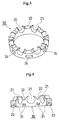
- Figs. 1 to 3 show a retainer for use of rolling bearing as the first embodiment of the present invention.
- the whole structure of a retainer 20 is identical with the crown type of retainer 1 shown in Fig. 5, in which a plurality of pockets 21 retaining a plurality of balls are provided on one end at an equal spacing in the circular direction, and between the adjacent pockets 21 a plane connecting portion 22 is disposed.
- first recessed portions 23 (here eight) are provided on a pitch circle coaxially with the axis of the retainer at an equal spacing and on the periphery of the retainer 20 a plurality of second recessed portions 24 communicated with the first recessed portion 23 respectively are provided. That is, the retainer 20 is provided with a plurality of channels communicated through the back face and the periphery in the combination of the first recessed portion 23 and the second recessed portion 24.
- the retainer 20 is formed with a body molded with a resin such as a nylon 66 (trade name) and a polyphenylenesulfide (PPS), and said first and second recessed portions 23 and 24 are to be molded integrally at the time of molding the body.
- a resin such as a nylon 66 (trade name) and a polyphenylenesulfide (PPS)
- the lubricant is applied from outside to the pockets 21 and the connecting portions 22 of the retainer 20.
- the lubricant is applied to the recessed portion 23 of the back face side in order or at one time.
- this lubricant flows from the second recessed portion 24 to the gap between the periphery of the retainer 20 and the inner circumferential surface of the outer race sleeve 11, and further into the bearing 10 through the gap, and further flows to the pocket 21 and the connecting portion 22. Then, since the channels formed with the first and second recessed portions 23 and 24 are provided in a plurality at an equal spacing in the circular direction, the lubricant flows into a front of the retainer through the channels approximately equally.
- Fig. 4 shows a second embodiment of a retainer 30 for a rolling bearing of the present invention.
- the whole structure of this retainer 30 is identical with the one of the retainer 20 shown in Fig. 1, so the identical portions are attached with the identical signs.
- the feature of the second embodiment resides in that, in place of the second recessed portion 24 of the periphery of the first embodiment, a third recessed portion 31 in communication with each first recessed portion 23 is provided on the inner circumferential surface.
- the lubricant applied to the first recessed portion 23 flows in the bearing 10 through the gap between the inner circumferential surface of the retainer 30 and a large diameter portion 14a (Fig.
- the second recessed portions 24 and in the second embodiment the third recessed portions 31 are adapted to be provided respectively on the periphery and on the inner circumferential surface.
- these second recessed portion 24 and third recessed portion 31 may be provided together, in this case the lubricant can be applied more effectively in the bearing 10.
- the number and shape of the recessed portions 23, 24 and 31 are free to set, not only the recessed portions of less or more than 8 in number may be provided, but also the different shape such as circular and oval may be employed.
- the first recessed portion 23 of the back face side may be replaced with an annular groove and the second and third recessed portions 24 and 31 may be replaced with a circular groove.
- the first recessed portion 23 of the back face side is replaced with the annular groove, it possible to apply the lubricant to each of the channels at one time using a supplier in common, and further in the case where the second and third recessed portions of the outer and inner circumferential surfaces 24 and 31 are replaced with the circular groove, the lubricant can be more uniformly applied in the circular direction.
- the lubricant can be applied to the necessary portions in the bearing approximately uniformly to contribute to solve the variation of the bearing torque and reduce it greatly.
Landscapes
- Engineering & Computer Science (AREA)
- General Engineering & Computer Science (AREA)
- Mechanical Engineering (AREA)
- Rolling Contact Bearings (AREA)
Applications Claiming Priority (2)
| Application Number | Priority Date | Filing Date | Title |
|---|---|---|---|
| JP20032699 | 1999-07-14 | ||
| JP11200326A JP2001027248A (ja) | 1999-07-14 | 1999-07-14 | 転がり軸受用保持器 |
Publications (2)
| Publication Number | Publication Date |
|---|---|
| EP1069328A1 true EP1069328A1 (de) | 2001-01-17 |
| EP1069328B1 EP1069328B1 (de) | 2006-08-02 |
Family
ID=16422446
Family Applications (1)
| Application Number | Title | Priority Date | Filing Date |
|---|---|---|---|
| EP00113431A Expired - Lifetime EP1069328B1 (de) | 1999-07-14 | 2000-06-24 | Käfig für Wälzlager |
Country Status (4)
| Country | Link |
|---|---|
| US (2) | US6402386B1 (de) |
| EP (1) | EP1069328B1 (de) |
| JP (1) | JP2001027248A (de) |
| DE (1) | DE60029695T8 (de) |
Cited By (2)
| Publication number | Priority date | Publication date | Assignee | Title |
|---|---|---|---|---|
| DE102004003106B4 (de) * | 2003-01-31 | 2006-05-11 | Skf Industrie S.P.A. | Käfig für Walzkörperlager |
| EP3267057A1 (de) * | 2016-07-06 | 2018-01-10 | Regal Beloit America, Inc. | Lagerhalterung, lager und zugehöriges verfahren |
Families Citing this family (21)
| Publication number | Priority date | Publication date | Assignee | Title |
|---|---|---|---|---|
| FR2821651B1 (fr) * | 2001-03-01 | 2004-05-14 | Roulements Soc Nouvelle | Cage a reserve de substance lubrifiante |
| US7507028B2 (en) * | 2005-06-27 | 2009-03-24 | Spx Corporation | Bearing retainer assembly and method |
| FR2900996B1 (fr) * | 2006-05-12 | 2008-08-08 | Skf Ab | Cage pour roulement a billes |
| FR2911934B1 (fr) * | 2007-01-26 | 2009-09-18 | Skf Ab | Cage pour roulement a billes |
| DE102007061589B4 (de) * | 2007-01-29 | 2017-06-22 | Nsk Ltd. | Kugellager und Halterungskonstruktion |
| JP2008256168A (ja) * | 2007-04-09 | 2008-10-23 | Jtekt Corp | 転がり軸受用保持器およびそれを具備した風力発電用軸受 |
| FR2921451B1 (fr) * | 2007-09-26 | 2010-02-26 | Skf Ab | Palier a roulement et cage pour un tel palier |
| CN101978181B (zh) * | 2008-03-21 | 2014-04-09 | Ntn株式会社 | 滚珠轴承用保持器和具有它的滚珠轴承及其制造方法 |
| DE102008025502A1 (de) * | 2008-05-28 | 2009-12-03 | Ab Skf | Getriebelager-Montageeinheit und Getriebelager |
| JP5565101B2 (ja) * | 2010-05-27 | 2014-08-06 | 株式会社ジェイテクト | ころ軸受 |
| JP5615649B2 (ja) * | 2010-09-28 | 2014-10-29 | Ntn株式会社 | 玉軸受 |
| WO2012072110A1 (en) | 2010-11-30 | 2012-06-07 | Aktiebolaget Skf | Comb cage for ball bearing and ball bearing with such a cage |
| JP5703894B2 (ja) * | 2011-03-29 | 2015-04-22 | 日本精工株式会社 | 玉軸受 |
| US20120251027A1 (en) * | 2011-04-04 | 2012-10-04 | Seagate Technology Llc | Methods and devices for making and using cages for bearing assemblies |
| US20120308172A1 (en) * | 2011-06-01 | 2012-12-06 | Schaeffler Technologies Gmbh & Co. Kg | Double row, tandem, angular contact, ball bearing assembly |
| US8979383B2 (en) * | 2011-10-10 | 2015-03-17 | General Electric Company | Dynamically-lubricated bearing and method of dynamically lubricating a bearing |
| CN104246252B (zh) * | 2012-04-10 | 2017-09-22 | 舍弗勒技术股份两合公司 | 柔性轴承罩 |
| US20140369636A1 (en) * | 2013-06-17 | 2014-12-18 | Minebea Co., Ltd. | Ball bearing assembly to improve lubricating performance |
| DE102014212531A1 (de) * | 2013-07-23 | 2015-01-29 | Schaeffler Technologies Gmbh & Co. Kg | Lagerkäfig mit Fettreservoirs für Selbstschmierung |
| US9518606B2 (en) | 2015-03-09 | 2016-12-13 | Seagate Technology Llc | Bearing apparatus with surface migration channels |
| DE102015223510A1 (de) | 2015-11-27 | 2017-06-01 | Schaeffler Technologies AG & Co. KG | Wälzlagerkäfig |
Citations (5)
| Publication number | Priority date | Publication date | Assignee | Title |
|---|---|---|---|---|
| CH257814A (fr) * | 1944-11-01 | 1948-10-31 | Armstrong Siddeley Motors Ltd | Palier à roulement. |
| JPS61215811A (ja) * | 1986-03-28 | 1986-09-25 | Koyo Seiko Co Ltd | 玉軸受用合成樹脂装冠形保持器 |
| EP0394088A1 (de) * | 1989-04-18 | 1990-10-24 | S.N.R. Roulements | Schmierender Käfig für ein Kugellager |
| EP0486218A1 (de) * | 1990-11-15 | 1992-05-20 | International Business Machines Corporation | Kugellager |
| DE19521855A1 (de) * | 1994-07-19 | 1996-01-25 | Balzers Pfeiffer Gmbh | Kugellager mit Ölversorgung |
Family Cites Families (6)
| Publication number | Priority date | Publication date | Assignee | Title |
|---|---|---|---|---|
| US3743369A (en) * | 1971-09-08 | 1973-07-03 | Skf Ind Trading & Dev | Cage for a rolling bearing |
| DE3300653A1 (de) * | 1983-01-11 | 1984-07-12 | FAG Kugelfischer Georg Schäfer KGaA, 8720 Schweinfurt | Axial ausformbarer kammkaefig fuer kugellager |
| DE3821613C2 (de) * | 1988-06-27 | 1996-06-20 | Kugelfischer G Schaefer & Co | Kammkäfig für Kugellager |
| US4938613A (en) * | 1989-07-24 | 1990-07-03 | General Motors Corporation | Moldable plastic bearing ball retainer |
| US5137376A (en) * | 1990-08-22 | 1992-08-11 | Fag Kugelfischer Georg Schafer | Comb separator for ball bearings |
| JP3007580B2 (ja) * | 1996-12-20 | 2000-02-07 | 株式会社シマノ | 軸受の伸縮リテーナー |
-
1999
- 1999-07-14 JP JP11200326A patent/JP2001027248A/ja active Pending
-
2000
- 2000-06-14 US US09/593,455 patent/US6402386B1/en not_active Expired - Lifetime
- 2000-06-24 EP EP00113431A patent/EP1069328B1/de not_active Expired - Lifetime
- 2000-06-24 DE DE60029695T patent/DE60029695T8/de not_active Expired - Fee Related
-
2002
- 2002-04-26 US US10/132,198 patent/US20020114550A1/en not_active Abandoned
Patent Citations (5)
| Publication number | Priority date | Publication date | Assignee | Title |
|---|---|---|---|---|
| CH257814A (fr) * | 1944-11-01 | 1948-10-31 | Armstrong Siddeley Motors Ltd | Palier à roulement. |
| JPS61215811A (ja) * | 1986-03-28 | 1986-09-25 | Koyo Seiko Co Ltd | 玉軸受用合成樹脂装冠形保持器 |
| EP0394088A1 (de) * | 1989-04-18 | 1990-10-24 | S.N.R. Roulements | Schmierender Käfig für ein Kugellager |
| EP0486218A1 (de) * | 1990-11-15 | 1992-05-20 | International Business Machines Corporation | Kugellager |
| DE19521855A1 (de) * | 1994-07-19 | 1996-01-25 | Balzers Pfeiffer Gmbh | Kugellager mit Ölversorgung |
Non-Patent Citations (1)
| Title |
|---|
| PATENT ABSTRACTS OF JAPAN vol. 011, no. 054 (M - 563) 19 February 1987 (1987-02-19) * |
Cited By (2)
| Publication number | Priority date | Publication date | Assignee | Title |
|---|---|---|---|---|
| DE102004003106B4 (de) * | 2003-01-31 | 2006-05-11 | Skf Industrie S.P.A. | Käfig für Walzkörperlager |
| EP3267057A1 (de) * | 2016-07-06 | 2018-01-10 | Regal Beloit America, Inc. | Lagerhalterung, lager und zugehöriges verfahren |
Also Published As
| Publication number | Publication date |
|---|---|
| US20020114550A1 (en) | 2002-08-22 |
| JP2001027248A (ja) | 2001-01-30 |
| EP1069328B1 (de) | 2006-08-02 |
| DE60029695T2 (de) | 2007-08-02 |
| DE60029695T8 (de) | 2007-11-08 |
| DE60029695D1 (de) | 2006-09-14 |
| US6402386B1 (en) | 2002-06-11 |
Similar Documents
| Publication | Publication Date | Title |
|---|---|---|
| US6402386B1 (en) | Retainer for rolling bearing | |
| US4810108A (en) | Bearing | |
| JP4432058B2 (ja) | 車輪軸受の外レース及び外レースの止め装置 | |
| US4138169A (en) | Two row rolling bearing assembly having single piece inner ring and two piece outer ring | |
| JPS5977122A (ja) | 車輪ボスの軸受装置 | |
| JP2000065049A (ja) | 自動車用ハブユニット及びその組立方法 | |
| US7198408B2 (en) | Shaft bearing retainer | |
| JP2003028163A (ja) | 玉軸受用保持器 | |
| JP2000065049A5 (de) | ||
| JP2007113592A (ja) | 合成樹脂製転がり軸受用保持器及び転がり軸受 | |
| EP1069327B1 (de) | Wälzlagerkäfig, und Wälzlager mit diesem Käfig | |
| JP2005180630A (ja) | 車輪用軸受装置およびアンギュラ玉軸受 | |
| JP2998626B2 (ja) | アンギュラ型玉軸受用合成樹脂製保持器 | |
| EP0771003A3 (de) | Mehrteiliger Lagerzusammenbau für den Schwenkarm eines Festplattenlaufwerks | |
| JP2000094902A (ja) | 自動車用ハブユニット及びその組立方法 | |
| JPH08226439A (ja) | 複列玉軸受 | |
| JP4244955B2 (ja) | 自動車用ハブユニットの組立方法 | |
| JPS59155622A (ja) | コロ軸受用プラスチツク製保持器 | |
| JP2000046058A (ja) | 転がり軸受用保持器 | |
| JPS58166126A (ja) | 直動玉軸受 | |
| JP3849816B2 (ja) | アンギュラ玉軸受 | |
| JP3928922B2 (ja) | 玉軸受 | |
| JP2000002245A (ja) | スラスト玉軸受用プラスチック製保持器 | |
| JPH09303407A (ja) | ベアリング | |
| JP2593689Y2 (ja) | ディスククランプ装置 |
Legal Events
| Date | Code | Title | Description |
|---|---|---|---|
| PUAI | Public reference made under article 153(3) epc to a published international application that has entered the european phase |
Free format text: ORIGINAL CODE: 0009012 |
|
| AK | Designated contracting states |
Kind code of ref document: A1 Designated state(s): DE GB |
|
| AX | Request for extension of the european patent |
Free format text: AL;LT;LV;MK;RO;SI |
|
| 17P | Request for examination filed |
Effective date: 20010302 |
|
| R17P | Request for examination filed (corrected) |
Effective date: 20010302 |
|
| AKX | Designation fees paid |
Free format text: DE GB |
|
| 17Q | First examination report despatched |
Effective date: 20040401 |
|
| GRAP | Despatch of communication of intention to grant a patent |
Free format text: ORIGINAL CODE: EPIDOSNIGR1 |
|
| GRAS | Grant fee paid |
Free format text: ORIGINAL CODE: EPIDOSNIGR3 |
|
| GRAA | (expected) grant |
Free format text: ORIGINAL CODE: 0009210 |
|
| AK | Designated contracting states |
Kind code of ref document: B1 Designated state(s): DE GB |
|
| REG | Reference to a national code |
Ref country code: GB Ref legal event code: FG4D |
|
| REF | Corresponds to: |
Ref document number: 60029695 Country of ref document: DE Date of ref document: 20060914 Kind code of ref document: P |
|
| PLBE | No opposition filed within time limit |
Free format text: ORIGINAL CODE: 0009261 |
|
| STAA | Information on the status of an ep patent application or granted ep patent |
Free format text: STATUS: NO OPPOSITION FILED WITHIN TIME LIMIT |
|
| 26N | No opposition filed |
Effective date: 20070503 |
|
| PGFP | Annual fee paid to national office [announced via postgrant information from national office to epo] |
Ref country code: DE Payment date: 20080703 Year of fee payment: 9 |
|
| PGFP | Annual fee paid to national office [announced via postgrant information from national office to epo] |
Ref country code: GB Payment date: 20080625 Year of fee payment: 9 |
|
| GBPC | Gb: european patent ceased through non-payment of renewal fee |
Effective date: 20090624 |
|
| PG25 | Lapsed in a contracting state [announced via postgrant information from national office to epo] |
Ref country code: GB Free format text: LAPSE BECAUSE OF NON-PAYMENT OF DUE FEES Effective date: 20090624 |
|
| PG25 | Lapsed in a contracting state [announced via postgrant information from national office to epo] |
Ref country code: DE Free format text: LAPSE BECAUSE OF NON-PAYMENT OF DUE FEES Effective date: 20100101 |