EP1069248A2 - Dispositif de manoeuvre - Google Patents
Dispositif de manoeuvre Download PDFInfo
- Publication number
- EP1069248A2 EP1069248A2 EP00112976A EP00112976A EP1069248A2 EP 1069248 A2 EP1069248 A2 EP 1069248A2 EP 00112976 A EP00112976 A EP 00112976A EP 00112976 A EP00112976 A EP 00112976A EP 1069248 A2 EP1069248 A2 EP 1069248A2
- Authority
- EP
- European Patent Office
- Prior art keywords
- actuator
- lock
- carrier
- locking device
- actuators
- Prior art date
- Legal status (The legal status is an assumption and is not a legal conclusion. Google has not performed a legal analysis and makes no representation as to the accuracy of the status listed.)
- Withdrawn
Links
Images


Classifications
-
- G—PHYSICS
- G05—CONTROLLING; REGULATING
- G05G—CONTROL DEVICES OR SYSTEMS INSOFAR AS CHARACTERISED BY MECHANICAL FEATURES ONLY
- G05G5/00—Means for preventing, limiting or returning the movements of parts of a control mechanism, e.g. locking controlling member
- G05G5/28—Means for preventing, limiting or returning the movements of parts of a control mechanism, e.g. locking controlling member for preventing unauthorised access to the controlling member or its movement to a command position
-
- E—FIXED CONSTRUCTIONS
- E02—HYDRAULIC ENGINEERING; FOUNDATIONS; SOIL SHIFTING
- E02F—DREDGING; SOIL-SHIFTING
- E02F9/00—Component parts of dredgers or soil-shifting machines, not restricted to one of the kinds covered by groups E02F3/00 - E02F7/00
- E02F9/20—Drives; Control devices
- E02F9/2004—Control mechanisms, e.g. control levers
-
- E—FIXED CONSTRUCTIONS
- E02—HYDRAULIC ENGINEERING; FOUNDATIONS; SOIL SHIFTING
- E02F—DREDGING; SOIL-SHIFTING
- E02F9/00—Component parts of dredgers or soil-shifting machines, not restricted to one of the kinds covered by groups E02F3/00 - E02F7/00
- E02F9/24—Safety devices, e.g. for preventing overload
-
- Y—GENERAL TAGGING OF NEW TECHNOLOGICAL DEVELOPMENTS; GENERAL TAGGING OF CROSS-SECTIONAL TECHNOLOGIES SPANNING OVER SEVERAL SECTIONS OF THE IPC; TECHNICAL SUBJECTS COVERED BY FORMER USPC CROSS-REFERENCE ART COLLECTIONS [XRACs] AND DIGESTS
- Y10—TECHNICAL SUBJECTS COVERED BY FORMER USPC
- Y10T—TECHNICAL SUBJECTS COVERED BY FORMER US CLASSIFICATION
- Y10T74/00—Machine element or mechanism
- Y10T74/20—Control lever and linkage systems
- Y10T74/20012—Multiple controlled elements
- Y10T74/20018—Transmission control
- Y10T74/20085—Restriction of shift, gear selection, or gear engagement
- Y10T74/20104—Shift element interlock
- Y10T74/20116—Resiliently biased interlock
Definitions
- the invention relates to an actuating device at least one actuator and a movable support, and a vehicle with a lifting or loading device.
- DE-C2-24 50 545 discloses an actuator for a front loader on a tractor.
- the Actuator includes a handle that runs over a rope is connected to the tool of the front loader.
- the Actuator is vertical on the top end pivoted console arranged in one operating and one Can be brought out of operation.
- the BAAS TRIMA front loader brochure, B&P 5,000 printing shows on page 5 a single lever control of a front loader, the is provided with a safety circuit.
- This Safety switch can be activated using a small lever the controller is blocked.
- the problem underlying the invention is seen in that the actuator in particular in the Decommissioning the console is not sufficient against one unintended operation is protected, and that from one Vehicle with a lifting or loading device at a unintentional operation can pose a danger.
- Activation can e.g. B. by mechanical Press, but also by a touching or non-contact Switching operation. So on the one hand it is already due to the position of the wearer visible whether an actuation is possible or not and it becomes an unintended one Movement of the wearer prevented in a position in which the Actuator not visible or erroneous is operable.
- a position in which an activation of the Actuator should not be possible both be a non-operational position as well as any position of the wearer outside the operating position, the more Freedom of movement for an operator, freedom for one creates swiveling driver's seat, storage space or the like.
- a simple and reliable way of moving the wearer or to prevent activation of the actuator is seen in the use of a mechanical latch that in engagement with the actuator or actuators Lock can be brought.
- the optional intervention option provides sure that either the adjustment of the carrier or the Locking is possible - but not both.
- the bolt can also be electrically by means of a magnet or The like are adjusted or executed and always then its locking the lock or actuator Take a position when the other component is movable or can be actuated.
- the lock can be made mechanically and therefore very robust his.
- an electrical lock has its purpose there, where spatial circumstances are a simple guide to a mechanical Do not allow linkage or linkage to other Signals should be made.
- a rod or a traction means e.g. B. a rope
- a rod or a traction means e.g. B. a rope
- the corresponding position of the Lock resulting from a relative change in position of the wearer in relation to a fixed camp is said to result caused that the mechanical lock eccentric to the Pivot axis of the carrier is connected.
- the measure of The adjustment path of the lock can be varied eccentrically.
- the actuating device proves to be particularly advantageous on a tractor with a front loader because the latter e.g. T. is used only briefly but in Out of service condition on the tractor remains attached.
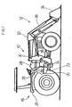
- FIG. 1 shows an agricultural tractor 10 with a front loader 12 and an actuator 14.
- the agricultural tractor 10 is with an operating platform 16 equipped from where, among other things, the operation of the Front loader 12 can be controlled.
- the operating platform 16 includes a bottom 18 with a bearing 20 and a pivot axis 22.
- a passage 24 allows one Operator operating platform 16 between one Mudguard 26 and a dashboard 28 to leave.
- the front loader 12 has, inter alia, a holding bracket 30, a rocker 32, a tool 34 and a plurality of hydraulic motors 36 on.
- the holding bracket 30 is used for the vertically pivotable connection the swing arm 32 to the tractor 10.
- the rocker 32 can be compared to a footprint in any number of positions are brought, including a first sentence is extended or retracted by hydraulic motors 36.
- the tool 34 is shown as an example of a blade. In fact, there are a variety of different tools 34, which is well known, and which is also used could become.
- the position of the tool 34 relative to the Swing 32 is made using a different set of Hydraulic motors 36 determined.
- the hydraulic motors 36 are operated in a manner not shown Hydraulic system of the agricultural tractor 10 acted upon and by means of the actuator 14 controlled.
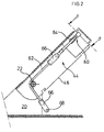
- the actuator 14 is in a first Embodiment shown in more detail in Figures 2 to 5 and consists of a shift lever 38, at least one Actuator 40, a locking device 42, one Lock 44 and a carrier 46 together.
- the shift lever 38 can assume various positions, in which each not shown valves for controlling the Hydraulic motors 36 are operated. In a conventional way the shift lever 38 can preferably be gimbal-mounted and front and rear, as well as side switch positions take in.
- Each actuator 40 transmits that from the shift lever 38 initiated movement on the valve - either mechanically, e.g. B. by means of a Bowden cable, or electrically by means of cables or wireless.
- each is Actuator 40 as an axially adjustable slide shown, the more on the bottom plate of a housing 48 or can stand out less. Alternatively, that could be Actuator can also be designed as a switch. The remaining part of the housing 48 with the storage of the Shift lever 38 is not shown.
- On the peripheral surface each actuator 40 is a recess 50 in the manner an annular groove provided. There are two in FIGS. 4 and 5 Actuators 40 shown; however, more can be done or less.
- the locking device 42 serves to activate the Actuators 40 in at least one particular situation to prevent e.g. B. when the carrier 46 is not in its operating position. From a different perspective the carrier 46 should only be able to be pivoted when the Actuators 40 are locked. That way avoided that z. B. the swing arm 32 is lowered, though someone is below her.
- a latch 52 which is in the form of a metal plate formed and slidably mounted in the housing 48.
- the bolt 52 can be in positive engagement with the recesses 50 brought and forms with them Locking device 42; in this case they are Actuators 40 locked.
- the shape of the latch 52 is like this chosen that he either in the recesses 50 of Actuators 40 or in a recess 50 'of the lock 44th intervenes.
- appropriately dimensioned on the latch 52 Provided noses.
- the latch 52 contains a handle 58.
- this is by means of tabs designed as plates simply covered and can therefore no longer be operated.
- the lock 44 contains the present one Embodiment a slider 60 and a traction device 62. Der The purpose of lock 44 is twofold - on the one hand, it should prevent the carrier 46 from being in an inoperative position is pivoted as long as the actuators 40 are activated can be; on the other hand, it should be the actuators 40 block directly or indirectly if the wearer 46 is outside of its operating position.
- the slider 60 is comparable to that Actuators 40 are longitudinally movable in the housing 48 and is always biased by a spring 64 so that it moves so far into the plane of movement of the bolt 52 (Fig. 3) that the latch 52 enter the recess 50 ' can.
- the actuators 40 are thus free. Will the feather 64, however, completely tensioned, the slide 60 is almost completely outside, d. H. below the plane of movement of the bolt 52, whereby then - see Figure 2 - the bolt 52 in the recess 50 of the actuators 40 engages and this locks.
- the traction means 62 is in this embodiment as a rope trained, the two ends with a fork-shaped Connection means 66 is provided.
- the upper Connection means 66 is the traction means 62 with the slide 60
- the lower connecting means 66 is the traction means 62 connected to the bearing 20.
- the connection is made in each case swiveling and variable in length at least on one side.
- the traction means 62 is between the two connecting means 66 the pivot axis 22 out.
- connection of the lower Connection means 66 with the bearing 20 is eccentric to the Pivot axis 22, namely at a bearing point located in this way 68 that in one end position the traction means 62 at least in runs essentially straight while in another End position the traction device 62 is deflected and on a two-legged path runs, with the legs in the Hit pivot axis 22.
- a resulting redirection causes a while the length of the traction means 62 Movement of the slider 60 when the carrier 46 is pivoted.
- the bolt 52, the slots 54 and the pins 56 run in essentially symmetrical to a central axis.
- the latch 52 joins the end area in the drawing below the handle 58 out of the housing 48 and is in the Longitudinally movable, the lower closed slot 54 with the pin 56 accommodated therein, the freedom of movement of the bolt 52 determined.
- Noses are designed and arranged so that in one Out of service end position (Fig. 5) two associated lugs engage in the recesses 50 of the actuators 40, in the recess 50 'in the slide 60, however, is not. In this Position hits the pin 56 on one end of the Slot 54 on.
- the latch 52 does not fit into the recess 50 ' can intervene because this is above the movement level of the latch 52 is located. Rather, the corresponding nose would strike against the undiminished circumference of the slide 60. Out this arrangement follows that the latch 52 is not in one Actuators 40 can reach the unlocking position as long as the lock 44 is in its inoperative state.
- the two are in an operating end position (FIG. 4) associated noses out of engagement with the recesses 50 of the actuators 40, while that of the lock 44 assigned nose into the recess 50 'in the slide 60 intervenes and thus prevents its movement.
- This Position beats the pin 56 on the opposite End side of the slot 54.
- the latch 52 can be both its actuators 40 take blocking as well as releasing position.
- the carrier 46 If the carrier 46 is now to be in its operating position according to FIG. 3 take and the activation of the actuators 40th are made possible, it is in its operating position according to the figure 3 to pivot. Since the traction means 62 then the direct and shorter path between the slide 60 and the bearing 68 bridged, the spring 64 moves the slider 60 further over the Bottom surface of the housing 48 so that its recess 50 ' arrives in the plane of movement of the bolt 52 and this out its position blocking the actuators 40 can be moved out. Then the latch 52 is in his Movement completely free and the actuators 40 can be activated by the shift lever 38. Optionally can the latch 52 is also brought into its blocking position going to operate the front loader 12 even then avoid when the carrier 46 is in its operating position located.
- Figure 6 shows a slightly modified embodiment of the Actuator 14.
Landscapes
- Engineering & Computer Science (AREA)
- Mining & Mineral Resources (AREA)
- Structural Engineering (AREA)
- General Engineering & Computer Science (AREA)
- Civil Engineering (AREA)
- General Physics & Mathematics (AREA)
- Automation & Control Theory (AREA)
- Physics & Mathematics (AREA)
- Computer Security & Cryptography (AREA)
- Component Parts Of Construction Machinery (AREA)
- Agricultural Machines (AREA)
- Lifting Devices For Agricultural Implements (AREA)
- Lock And Its Accessories (AREA)
- Spinning Or Twisting Of Yarns (AREA)
- Handcart (AREA)
Applications Claiming Priority (2)
| Application Number | Priority Date | Filing Date | Title |
|---|---|---|---|
| DE19932286 | 1999-07-10 | ||
| DE19932286A DE19932286A1 (de) | 1999-07-10 | 1999-07-10 | Betätigungsvorrichtung |
Publications (2)
| Publication Number | Publication Date |
|---|---|
| EP1069248A2 true EP1069248A2 (fr) | 2001-01-17 |
| EP1069248A3 EP1069248A3 (fr) | 2001-04-04 |
Family
ID=7914328
Family Applications (1)
| Application Number | Title | Priority Date | Filing Date |
|---|---|---|---|
| EP00112976A Withdrawn EP1069248A3 (fr) | 1999-07-10 | 2000-06-21 | Dispositif de manoeuvre |
Country Status (5)
| Country | Link |
|---|---|
| US (1) | US6435053B1 (fr) |
| EP (1) | EP1069248A3 (fr) |
| JP (1) | JP2001065001A (fr) |
| CA (1) | CA2313553C (fr) |
| DE (1) | DE19932286A1 (fr) |
Cited By (1)
| Publication number | Priority date | Publication date | Assignee | Title |
|---|---|---|---|---|
| USD1026968S1 (en) | 2022-11-04 | 2024-05-14 | Deere & Company | Loader carrier for implements |
Families Citing this family (4)
| Publication number | Priority date | Publication date | Assignee | Title |
|---|---|---|---|---|
| GB2402727A (en) * | 2003-06-14 | 2004-12-15 | Cnh Uk Ltd | Lockable joystick control with wrist support |
| US8267004B2 (en) * | 2009-05-20 | 2012-09-18 | Lifetime Enterprises, Llc | Adaptable hydraulic control system |
| US11001988B2 (en) * | 2018-06-18 | 2021-05-11 | Caterpillar Inc. | Controlling interlocks based on an interlock configuration |
| JP7026038B2 (ja) * | 2018-12-20 | 2022-02-25 | 株式会社クボタ | 作業車の操作機構 |
Family Cites Families (16)
| Publication number | Priority date | Publication date | Assignee | Title |
|---|---|---|---|---|
| CH85923A (de) * | 1919-10-04 | 1920-11-01 | Graf Jakob | Sicherheitskurbel. |
| US3492889A (en) * | 1968-03-18 | 1970-02-03 | Massey Ferguson Inc | Adjustable control stand |
| FR2288826A1 (fr) | 1974-10-24 | 1976-05-21 | Deere & Co | Dispositif de declenchement pour outil monte sur les bras de relevage d'un vehicule |
| US4222287A (en) * | 1978-03-27 | 1980-09-16 | Fiat-Allis Construction Machinery, Inc. | Multiple control locking device |
| US4366881A (en) * | 1980-12-11 | 1983-01-04 | J. I. Case Company | Flip-up control console |
| US4355819A (en) * | 1980-12-18 | 1982-10-26 | J.I. Case Company | Passive restraint system |
| US4526055A (en) * | 1981-04-21 | 1985-07-02 | Massey-Ferguson Services N.V. | Lockable control lever arrangement |
| US4429761A (en) * | 1981-08-17 | 1984-02-07 | Clark Equipment Company | Seat and control lever interlock |
| JPS58195221A (ja) * | 1982-04-21 | 1983-11-14 | Hitachi Constr Mach Co Ltd | ユニバ−サルレバ− |
| JPS6140929A (ja) * | 1984-07-31 | 1986-02-27 | Japan Steel Works Ltd:The | 油圧シヨベルの操縦装置 |
| JPS63194037A (ja) * | 1987-02-06 | 1988-08-11 | Yanmar Diesel Engine Co Ltd | 建設機械の操縦装置 |
| JPH02183818A (ja) * | 1989-01-11 | 1990-07-18 | Kyokuto Kaihatsu Kogyo Co Ltd | 操作レバーの安全装置 |
| US5325733A (en) * | 1993-02-11 | 1994-07-05 | Caterpillar Inc. | Work vehicle implement lever lock |
| DE4309885A1 (de) * | 1993-03-26 | 1994-09-29 | Vdo Schindling | Stellelement mit selbsttätig wirkender Sperreinrichtung |
| KR100211449B1 (ko) * | 1997-07-28 | 1999-08-02 | 추호석 | 로더용 페달록킹장치 |
| JPH11202960A (ja) * | 1998-01-09 | 1999-07-30 | Komatsu Est Corp | 作業用車両の作業機レバー支持構造 |
-
1999
- 1999-07-10 DE DE19932286A patent/DE19932286A1/de not_active Withdrawn
-
2000
- 2000-06-21 EP EP00112976A patent/EP1069248A3/fr not_active Withdrawn
- 2000-06-29 US US09/606,890 patent/US6435053B1/en not_active Expired - Fee Related
- 2000-07-07 CA CA002313553A patent/CA2313553C/fr not_active Expired - Fee Related
- 2000-07-10 JP JP2000207858A patent/JP2001065001A/ja active Pending
Cited By (1)
| Publication number | Priority date | Publication date | Assignee | Title |
|---|---|---|---|---|
| USD1026968S1 (en) | 2022-11-04 | 2024-05-14 | Deere & Company | Loader carrier for implements |
Also Published As
| Publication number | Publication date |
|---|---|
| CA2313553A1 (fr) | 2001-01-10 |
| DE19932286A1 (de) | 2001-01-11 |
| JP2001065001A (ja) | 2001-03-13 |
| CA2313553C (fr) | 2004-09-14 |
| EP1069248A3 (fr) | 2001-04-04 |
| US6435053B1 (en) | 2002-08-20 |
Similar Documents
| Publication | Publication Date | Title |
|---|---|---|
| DE4426207C5 (de) | Wähleinrichtung für ein Automatikgetriebe eines Kraftfahrzeugs | |
| EP1362956B1 (fr) | Dispositif pour verrouiller un outil sur un bras élévateur | |
| DE3333114C2 (fr) | ||
| DE102020203532A1 (de) | Joystickvorrichtungen mit variabler Spur und Arbeitsfahrzeuge, die diese beinhalten | |
| DE202008012484U1 (de) | Kraftfahrzeugschloß | |
| DE4333892A1 (de) | Manuell betätigbare mechanische Memory-Vorrichtung | |
| DE102016205485A1 (de) | Betätigungsvorrichtung zur Lehnenentriegelung mit zwei Betätigungselementen und einem Indikator zur Anzeige der Lehnenverriegelung | |
| DE69711975T2 (de) | Verriegelbare Not-aus-Taste | |
| EP1069248A2 (fr) | Dispositif de manoeuvre | |
| DE3932600A1 (de) | Fahrerabschnittskonstruktion fuer eine baumaschine | |
| DE102007014745A1 (de) | Elektrische Schalteinrichtung für ein Kraftfahrzeug | |
| DE10254031B4 (de) | Deichsel für Handgabelhubwagen | |
| EP2781811B1 (fr) | Dispositif d'aération | |
| EP1810561B1 (fr) | Dispositif de traction | |
| DE1958956C3 (de) | Fahrtrichtungsanzeigeschalter mit selbsttätiger Rückstellung durch die Lenkeinrichtung | |
| EP0230661A1 (fr) | Dispositif de changement de vitesse | |
| DE3722206A1 (de) | Steuereinrichtung fuer die betaetigung von magnetventilen an nutzfahrzeugen | |
| DE3431433C2 (fr) | ||
| DE1246429B (de) | Steuerhandgriff fuer Flurfoerderfahrzeuge | |
| DE3446918C2 (fr) | ||
| EP3192952B1 (fr) | Serrure de véhicule automobile | |
| DE69935293T2 (de) | Steuervorrichtung für eine Erdbewegungsmaschine | |
| DE1780488B2 (de) | Vorrichtung zur verstellung der lage einer sattelkupplung auf einer sattelzugmaschine | |
| EP1048513B1 (fr) | Dispositif de levier pour un dispositif de commande sur un siège de véhicule | |
| DE2545484A1 (de) | Vorrichtung zum begrenzen der schwenkbewegung eines rasenmaehergriffes |
Legal Events
| Date | Code | Title | Description |
|---|---|---|---|
| PUAI | Public reference made under article 153(3) epc to a published international application that has entered the european phase |
Free format text: ORIGINAL CODE: 0009012 |
|
| AK | Designated contracting states |
Kind code of ref document: A2 Designated state(s): AT DE ES FR GB SE |
|
| AX | Request for extension of the european patent |
Free format text: AL;LT;LV;MK;RO;SI |
|
| PUAL | Search report despatched |
Free format text: ORIGINAL CODE: 0009013 |
|
| AK | Designated contracting states |
Kind code of ref document: A3 Designated state(s): AT BE CH CY DE DK ES FI FR GB GR IE IT LI LU MC NL PT SE |
|
| AX | Request for extension of the european patent |
Free format text: AL;LT;LV;MK;RO;SI |
|
| RIC1 | Information provided on ipc code assigned before grant |
Free format text: 7E 02F 9/20 A, 7E 02F 9/24 B, 7G 05G 5/08 B, 7G 05G 5/28 B, 7G 05G 5/00 B, 7B 66F 9/20 B, 7B 66C 13/56 B |
|
| 17P | Request for examination filed |
Effective date: 20011004 |
|
| AKX | Designation fees paid |
Free format text: AT DE ES FR GB SE |
|
| STAA | Information on the status of an ep patent application or granted ep patent |
Free format text: STATUS: THE APPLICATION HAS BEEN WITHDRAWN |
|
| 18W | Application withdrawn |
Effective date: 20060130 |