EP1069248A2 - Operating device - Google Patents
Operating device Download PDFInfo
- Publication number
- EP1069248A2 EP1069248A2 EP00112976A EP00112976A EP1069248A2 EP 1069248 A2 EP1069248 A2 EP 1069248A2 EP 00112976 A EP00112976 A EP 00112976A EP 00112976 A EP00112976 A EP 00112976A EP 1069248 A2 EP1069248 A2 EP 1069248A2
- Authority
- EP
- European Patent Office
- Prior art keywords
- actuator
- lock
- carrier
- locking device
- actuators
- Prior art date
- Legal status (The legal status is an assumption and is not a legal conclusion. Google has not performed a legal analysis and makes no representation as to the accuracy of the status listed.)
- Withdrawn
Links
Images


Classifications
-
- G—PHYSICS
- G05—CONTROLLING; REGULATING
- G05G—CONTROL DEVICES OR SYSTEMS INSOFAR AS CHARACTERISED BY MECHANICAL FEATURES ONLY
- G05G5/00—Means for preventing, limiting or returning the movements of parts of a control mechanism, e.g. locking controlling member
- G05G5/28—Means for preventing, limiting or returning the movements of parts of a control mechanism, e.g. locking controlling member for preventing unauthorised access to the controlling member or its movement to a command position
-
- E—FIXED CONSTRUCTIONS
- E02—HYDRAULIC ENGINEERING; FOUNDATIONS; SOIL SHIFTING
- E02F—DREDGING; SOIL-SHIFTING
- E02F9/00—Component parts of dredgers or soil-shifting machines, not restricted to one of the kinds covered by groups E02F3/00 - E02F7/00
- E02F9/20—Drives; Control devices
- E02F9/2004—Control mechanisms, e.g. control levers
-
- E—FIXED CONSTRUCTIONS
- E02—HYDRAULIC ENGINEERING; FOUNDATIONS; SOIL SHIFTING
- E02F—DREDGING; SOIL-SHIFTING
- E02F9/00—Component parts of dredgers or soil-shifting machines, not restricted to one of the kinds covered by groups E02F3/00 - E02F7/00
- E02F9/24—Safety devices, e.g. for preventing overload
-
- Y—GENERAL TAGGING OF NEW TECHNOLOGICAL DEVELOPMENTS; GENERAL TAGGING OF CROSS-SECTIONAL TECHNOLOGIES SPANNING OVER SEVERAL SECTIONS OF THE IPC; TECHNICAL SUBJECTS COVERED BY FORMER USPC CROSS-REFERENCE ART COLLECTIONS [XRACs] AND DIGESTS
- Y10—TECHNICAL SUBJECTS COVERED BY FORMER USPC
- Y10T—TECHNICAL SUBJECTS COVERED BY FORMER US CLASSIFICATION
- Y10T74/00—Machine element or mechanism
- Y10T74/20—Control lever and linkage systems
- Y10T74/20012—Multiple controlled elements
- Y10T74/20018—Transmission control
- Y10T74/20085—Restriction of shift, gear selection, or gear engagement
- Y10T74/20104—Shift element interlock
- Y10T74/20116—Resiliently biased interlock
Definitions
- the invention relates to an actuating device at least one actuator and a movable support, and a vehicle with a lifting or loading device.
- DE-C2-24 50 545 discloses an actuator for a front loader on a tractor.
- the Actuator includes a handle that runs over a rope is connected to the tool of the front loader.
- the Actuator is vertical on the top end pivoted console arranged in one operating and one Can be brought out of operation.
- the BAAS TRIMA front loader brochure, B&P 5,000 printing shows on page 5 a single lever control of a front loader, the is provided with a safety circuit.
- This Safety switch can be activated using a small lever the controller is blocked.
- the problem underlying the invention is seen in that the actuator in particular in the Decommissioning the console is not sufficient against one unintended operation is protected, and that from one Vehicle with a lifting or loading device at a unintentional operation can pose a danger.
- Activation can e.g. B. by mechanical Press, but also by a touching or non-contact Switching operation. So on the one hand it is already due to the position of the wearer visible whether an actuation is possible or not and it becomes an unintended one Movement of the wearer prevented in a position in which the Actuator not visible or erroneous is operable.
- a position in which an activation of the Actuator should not be possible both be a non-operational position as well as any position of the wearer outside the operating position, the more Freedom of movement for an operator, freedom for one creates swiveling driver's seat, storage space or the like.
- a simple and reliable way of moving the wearer or to prevent activation of the actuator is seen in the use of a mechanical latch that in engagement with the actuator or actuators Lock can be brought.
- the optional intervention option provides sure that either the adjustment of the carrier or the Locking is possible - but not both.
- the bolt can also be electrically by means of a magnet or The like are adjusted or executed and always then its locking the lock or actuator Take a position when the other component is movable or can be actuated.
- the lock can be made mechanically and therefore very robust his.
- an electrical lock has its purpose there, where spatial circumstances are a simple guide to a mechanical Do not allow linkage or linkage to other Signals should be made.
- a rod or a traction means e.g. B. a rope
- a rod or a traction means e.g. B. a rope
- the corresponding position of the Lock resulting from a relative change in position of the wearer in relation to a fixed camp is said to result caused that the mechanical lock eccentric to the Pivot axis of the carrier is connected.
- the measure of The adjustment path of the lock can be varied eccentrically.
- the actuating device proves to be particularly advantageous on a tractor with a front loader because the latter e.g. T. is used only briefly but in Out of service condition on the tractor remains attached.
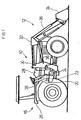
- FIG. 1 shows an agricultural tractor 10 with a front loader 12 and an actuator 14.
- the agricultural tractor 10 is with an operating platform 16 equipped from where, among other things, the operation of the Front loader 12 can be controlled.
- the operating platform 16 includes a bottom 18 with a bearing 20 and a pivot axis 22.
- a passage 24 allows one Operator operating platform 16 between one Mudguard 26 and a dashboard 28 to leave.
- the front loader 12 has, inter alia, a holding bracket 30, a rocker 32, a tool 34 and a plurality of hydraulic motors 36 on.
- the holding bracket 30 is used for the vertically pivotable connection the swing arm 32 to the tractor 10.
- the rocker 32 can be compared to a footprint in any number of positions are brought, including a first sentence is extended or retracted by hydraulic motors 36.
- the tool 34 is shown as an example of a blade. In fact, there are a variety of different tools 34, which is well known, and which is also used could become.
- the position of the tool 34 relative to the Swing 32 is made using a different set of Hydraulic motors 36 determined.
- the hydraulic motors 36 are operated in a manner not shown Hydraulic system of the agricultural tractor 10 acted upon and by means of the actuator 14 controlled.
- the actuator 14 is in a first Embodiment shown in more detail in Figures 2 to 5 and consists of a shift lever 38, at least one Actuator 40, a locking device 42, one Lock 44 and a carrier 46 together.
- the shift lever 38 can assume various positions, in which each not shown valves for controlling the Hydraulic motors 36 are operated. In a conventional way the shift lever 38 can preferably be gimbal-mounted and front and rear, as well as side switch positions take in.
- Each actuator 40 transmits that from the shift lever 38 initiated movement on the valve - either mechanically, e.g. B. by means of a Bowden cable, or electrically by means of cables or wireless.
- each is Actuator 40 as an axially adjustable slide shown, the more on the bottom plate of a housing 48 or can stand out less. Alternatively, that could be Actuator can also be designed as a switch. The remaining part of the housing 48 with the storage of the Shift lever 38 is not shown.
- On the peripheral surface each actuator 40 is a recess 50 in the manner an annular groove provided. There are two in FIGS. 4 and 5 Actuators 40 shown; however, more can be done or less.
- the locking device 42 serves to activate the Actuators 40 in at least one particular situation to prevent e.g. B. when the carrier 46 is not in its operating position. From a different perspective the carrier 46 should only be able to be pivoted when the Actuators 40 are locked. That way avoided that z. B. the swing arm 32 is lowered, though someone is below her.
- a latch 52 which is in the form of a metal plate formed and slidably mounted in the housing 48.
- the bolt 52 can be in positive engagement with the recesses 50 brought and forms with them Locking device 42; in this case they are Actuators 40 locked.
- the shape of the latch 52 is like this chosen that he either in the recesses 50 of Actuators 40 or in a recess 50 'of the lock 44th intervenes.
- appropriately dimensioned on the latch 52 Provided noses.
- the latch 52 contains a handle 58.
- this is by means of tabs designed as plates simply covered and can therefore no longer be operated.
- the lock 44 contains the present one Embodiment a slider 60 and a traction device 62. Der The purpose of lock 44 is twofold - on the one hand, it should prevent the carrier 46 from being in an inoperative position is pivoted as long as the actuators 40 are activated can be; on the other hand, it should be the actuators 40 block directly or indirectly if the wearer 46 is outside of its operating position.
- the slider 60 is comparable to that Actuators 40 are longitudinally movable in the housing 48 and is always biased by a spring 64 so that it moves so far into the plane of movement of the bolt 52 (Fig. 3) that the latch 52 enter the recess 50 ' can.
- the actuators 40 are thus free. Will the feather 64, however, completely tensioned, the slide 60 is almost completely outside, d. H. below the plane of movement of the bolt 52, whereby then - see Figure 2 - the bolt 52 in the recess 50 of the actuators 40 engages and this locks.
- the traction means 62 is in this embodiment as a rope trained, the two ends with a fork-shaped Connection means 66 is provided.
- the upper Connection means 66 is the traction means 62 with the slide 60
- the lower connecting means 66 is the traction means 62 connected to the bearing 20.
- the connection is made in each case swiveling and variable in length at least on one side.
- the traction means 62 is between the two connecting means 66 the pivot axis 22 out.
- connection of the lower Connection means 66 with the bearing 20 is eccentric to the Pivot axis 22, namely at a bearing point located in this way 68 that in one end position the traction means 62 at least in runs essentially straight while in another End position the traction device 62 is deflected and on a two-legged path runs, with the legs in the Hit pivot axis 22.
- a resulting redirection causes a while the length of the traction means 62 Movement of the slider 60 when the carrier 46 is pivoted.
- the bolt 52, the slots 54 and the pins 56 run in essentially symmetrical to a central axis.
- the latch 52 joins the end area in the drawing below the handle 58 out of the housing 48 and is in the Longitudinally movable, the lower closed slot 54 with the pin 56 accommodated therein, the freedom of movement of the bolt 52 determined.
- Noses are designed and arranged so that in one Out of service end position (Fig. 5) two associated lugs engage in the recesses 50 of the actuators 40, in the recess 50 'in the slide 60, however, is not. In this Position hits the pin 56 on one end of the Slot 54 on.
- the latch 52 does not fit into the recess 50 ' can intervene because this is above the movement level of the latch 52 is located. Rather, the corresponding nose would strike against the undiminished circumference of the slide 60. Out this arrangement follows that the latch 52 is not in one Actuators 40 can reach the unlocking position as long as the lock 44 is in its inoperative state.
- the two are in an operating end position (FIG. 4) associated noses out of engagement with the recesses 50 of the actuators 40, while that of the lock 44 assigned nose into the recess 50 'in the slide 60 intervenes and thus prevents its movement.
- This Position beats the pin 56 on the opposite End side of the slot 54.
- the latch 52 can be both its actuators 40 take blocking as well as releasing position.
- the carrier 46 If the carrier 46 is now to be in its operating position according to FIG. 3 take and the activation of the actuators 40th are made possible, it is in its operating position according to the figure 3 to pivot. Since the traction means 62 then the direct and shorter path between the slide 60 and the bearing 68 bridged, the spring 64 moves the slider 60 further over the Bottom surface of the housing 48 so that its recess 50 ' arrives in the plane of movement of the bolt 52 and this out its position blocking the actuators 40 can be moved out. Then the latch 52 is in his Movement completely free and the actuators 40 can be activated by the shift lever 38. Optionally can the latch 52 is also brought into its blocking position going to operate the front loader 12 even then avoid when the carrier 46 is in its operating position located.
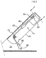
- Figure 6 shows a slightly modified embodiment of the Actuator 14.
Landscapes
- Engineering & Computer Science (AREA)
- Mining & Mineral Resources (AREA)
- Structural Engineering (AREA)
- General Engineering & Computer Science (AREA)
- Civil Engineering (AREA)
- General Physics & Mathematics (AREA)
- Automation & Control Theory (AREA)
- Physics & Mathematics (AREA)
- Computer Security & Cryptography (AREA)
- Component Parts Of Construction Machinery (AREA)
- Agricultural Machines (AREA)
- Lifting Devices For Agricultural Implements (AREA)
- Lock And Its Accessories (AREA)
- Spinning Or Twisting Of Yarns (AREA)
- Handcart (AREA)
Abstract
Description
Die Erfindung betrifft eine Betätigungsvorrichtung mit wenigstens einem Betätigungsglied und einem bewegbaren Träger, sowie ein Fahrzeug mit einer Hub- oder Ladevorrichtung.The invention relates to an actuating device at least one actuator and a movable support, and a vehicle with a lifting or loading device.
Die DE-C2-24 50 545 offenbart eine Betätigungsvorrichtung für einen Frontlader an einem Ackerschlepper. Die Betätigungsvorrichtung enthält einen Griff, der über ein Seil mit dem Werkzeug des Frontladers verbunden ist. Die Betätigungsvorrichtung ist auf dem oberen Ende einer vertikal schwenkbaren Konsole angeordnet, die in eine Betriebs- und eine Außerbetriebsstellung bringbar ist.DE-C2-24 50 545 discloses an actuator for a front loader on a tractor. The Actuator includes a handle that runs over a rope is connected to the tool of the front loader. The Actuator is vertical on the top end pivoted console arranged in one operating and one Can be brought out of operation.
Der Prospekt BAAS TRIMA Frontlader, Druckvermerk B&P 5.000 zeigt auf Seite 5 eine Einhebelsteuerung eines Frontladers, die mit einer Sicherheitsschaltung versehen ist. Dieser Sicherheitsschalter kann mittels eines kleinen Hebels aktiviert werden und blockiert die Steuerung.The BAAS TRIMA front loader brochure, B&P 5,000 printing shows on page 5 a single lever control of a front loader, the is provided with a safety circuit. This Safety switch can be activated using a small lever the controller is blocked.
Das der Erfindung zugrunde liegende Problem wird darin gesehen, daß die Betätigungsvorrichtung insbesondere in der Außerbetriebsstellung der Konsole nicht ausreichend gegen eine unbeabsichtigte Betätigung geschützt ist, und daß von einem Fahrzeug mit einer Hub- oder Ladevorrichtung bei einer unbeabsichtigten Betätigung Gefahren ausgehen können.The problem underlying the invention is seen in that the actuator in particular in the Decommissioning the console is not sufficient against one unintended operation is protected, and that from one Vehicle with a lifting or loading device at a unintentional operation can pose a danger.
Dieses Problem wird erfindungsgemäß durch die Lehre des Patentanspruchs 1 bzw. 7 gelöst, wobei in den weiteren Patentansprüchen Merkmale aufgeführt sind, die die Lösung in vorteilhafter Weise weiterentwickeln.This problem is solved according to the invention by the teaching of the patent claim 1 and 7 solved, wherein in the further claims Features are listed that make the solution more advantageous Evolve wisely.
Auf diese Weise kann eine Bewegung des Trägers verhindert werden, solange es noch möglich ist, die Betätigungsglieder zu aktivieren. Eine Aktivierung kann z. B. durch mechanisches Drücken, aber auch durch einen berührenden oder berührungslosen Schaltvorgang erfolgen. Demnach ist also einerseits schon aufgrund der Stellung des Trägers sichtbar, ob eine Betätigung möglich ist oder nicht, und es wird eine unbeabsichtigte Bewegung des Trägers in eine Stellung unterbunden, in der die Betätigungsvorrichtung nicht einsehbar oder irrtümlich bedienbar ist. Eine Stellung, in der eine Aktivierung der Betätigungsvorrichtung nicht möglich sein soll, kann sowohl eine Außerbetriebsstellung sein, wie auch irgendeine Stellung des Trägers außerhalb der Betriebsstellung, die mehr Bewegungsfreiraum für eine Bedienungsperson, Freiraum für einen schwenkbaren Fahrersitz, Stauraum oder dergleichen schafft.In this way, movement of the wearer can be prevented as long as it is still possible to close the actuators activate. Activation can e.g. B. by mechanical Press, but also by a touching or non-contact Switching operation. So on the one hand it is already due to the position of the wearer visible whether an actuation is possible or not and it becomes an unintended one Movement of the wearer prevented in a position in which the Actuator not visible or erroneous is operable. A position in which an activation of the Actuator should not be possible, both be a non-operational position as well as any position of the wearer outside the operating position, the more Freedom of movement for an operator, freedom for one creates swiveling driver's seat, storage space or the like.
Eine einfache und zuverlässige Weise, die Bewegung des Trägers oder eine Aktivierung der Betätigungsvorrichtung zu verhindern, wird in der Verwendung eines mechanischen Riegels gesehen, der in Eingriff mit dem bzw. den Betätigungsgliedern bzw. der Sperre bringbar ist. Die wahlweise Eingriffsmöglichkeit stellt sicher, daß entweder die Verstellung des Trägers oder der Sperre möglich ist - keinesfalls aber die beider.A simple and reliable way of moving the wearer or to prevent activation of the actuator, is seen in the use of a mechanical latch that in engagement with the actuator or actuators Lock can be brought. The optional intervention option provides sure that either the adjustment of the carrier or the Locking is possible - but not both.
Der Riegel kann auch elektrisch mittels eines Magneten oder dergleichen verstellt bzw. ausgeführt werden und stets dann seine die Sperre oder die Betätigungsvorrichtung verriegelnde Stellung einnehmen, wenn die jeweils andere Komponente bewegbar bzw. betätigbar ist.The bolt can also be electrically by means of a magnet or The like are adjusted or executed and always then its locking the lock or actuator Take a position when the other component is movable or can be actuated.
Die Sperre kann mechanisch und dadurch sehr robust ausgebildet sein. Andererseits hat eine elektrische Sperre dort ihren Sinn, wo räumliche Umstände eine einfache Führung eines mechanischen Gestänges nicht zulassen oder eine Verknüpfung mit weiteren Signalen vorgenommen werden soll.The lock can be made mechanically and therefore very robust his. On the other hand, an electrical lock has its purpose there, where spatial circumstances are a simple guide to a mechanical Do not allow linkage or linkage to other Signals should be made.
Mittels einer Stange oder eines Zugmittels, z. B. eines Seils, kann eine mechanische Sperre in einfacher und kostengünstiger Weise hergestellt werden. Die entsprechende Stellung der Sperre, die sich aus einer relativen Lageänderung des Trägers in Bezug auf ein ortsfestes Lager ergeben soll, wird dadurch hervorgerufen, daß die mechanische Sperre exzentrisch zu der Schwenkachse des Trägers angeschlossen wird. Mit dem Maß der Exzentrizität kann der Verstellweg der Sperre variiert werden. By means of a rod or a traction means, e.g. B. a rope, can be a mechanical lock in simple and inexpensive Way. The corresponding position of the Lock resulting from a relative change in position of the wearer in relation to a fixed camp is said to result caused that the mechanical lock eccentric to the Pivot axis of the carrier is connected. With the measure of The adjustment path of the lock can be varied eccentrically.
Infolge der Verwendung eines längs- oder linearverschiebbaren Betätigungsglieds mit entsprechenden Ausnehmungen ist es einfach möglich, die Verriegelungsvorrichtung bzw. deren Riegel in oder außer Eingriff zu bringen und damit eine Sperrwirkung zu erzielen oder nicht. Dabei findet der Formschluß einfach durch eine Bewegung des Riegels quer zu dem Betätigungsglied statt.Due to the use of a longitudinally or linearly displaceable It is the actuator with corresponding recesses easily possible, the locking device or its bolt to bring in or out of engagement and thus a blocking effect to achieve or not. The form fit is easy by moving the latch transversely to the actuator instead of.
Die Verwendung einer derart vorteilhaften Betätigungsvorrichtung bringt großen Nutzen an einem Fahrzeug, das mit einer Hub- oder Ladevorrichtung ausgerüstet ist, da von derartigen Vorrichtungen und Fahrzeug bei unsachgemäßer Handhabung eine nicht unerhebliche Gefahr ausgehen kann. Bei den Fahrzeugen kann es sich um landwirtschaftliche oder forstwirtschaftliche Fahrzeuge, aber auch um Fahrzeug im Bauwesen handeln. Folglich kommen als Hub- oder Ladevorrichtungen Drei -Punkt -Hydraulik, Ladeschaufeln, Fronthydraulik, Kräne und dergleichen in Betracht.The use of such an advantageous Actuator brings great benefits to a vehicle which is equipped with a lifting or loading device, because of such devices and vehicle when improper Handling can pose a not inconsiderable danger. At the vehicles can be agricultural or forestry vehicles, but also for vehicles in Trade construction. Consequently come as a hub or Loading devices three-point hydraulics, loading shovels, Front hydraulics, cranes and the like into consideration.
Von besonderem Vorteil erweist sich die Betätigungsvorrichtung an einem Ackerschlepper mit einem Frontlader, weil letzterer z. T. nur kurzzeitig verwendet wird aber im Außerbetriebszustand an dem Ackerschlepper angebaut bleibt.The actuating device proves to be particularly advantageous on a tractor with a front loader because the latter e.g. T. is used only briefly but in Out of service condition on the tractor remains attached.
In der Zeichnung ist ein nachfolgend näher beschriebenes Ausführungsbeispiel der Erfindung dargestellt. Es zeigt:
- Fig. 1
- einen Ackerschlepper mit einem Frontlader und einer Betätigungsvorrichtung mit einem Träger,
- Fig. 2
- die Betätigungsvorrichtung mit einer Sperre mit dem Träger in einer vergrößerten Darstellung in einer Außerbetriebsstellung, -
- Fig. 3
- die Betätigungsvorrichtung mit der Sperre mit dem Träger in einer vergrößerten Darstellung in einer Betriebsstellung,
- Fig. 4
- die Betätigungsvorrichtung in einer Ansicht auf die Ebene nach den Linien 4-4 und in der Blickrichtung der dazugehörigen Pfeile in der Betriebsstellung,
- Fig. 5
- die Betätigungsvorrichtung in einer Ansicht auf die Ebene nach den Linien 5-5 und in der Blickrichtung der dazugehörigen Pfeile in der Außerbetriebsstellung und
- Fig. 6
- ein anderes Ausführungsbeispiel der Sperre.
- Fig. 1
- an agricultural tractor with a front loader and an actuating device with a carrier,
- Fig. 2
- the actuating device with a lock with the carrier in an enlarged view in an inoperative position,
- Fig. 3
- the actuating device with the lock with the carrier in an enlarged view in an operating position,
- Fig. 4
- the actuating device in a view of the plane according to lines 4-4 and in the direction of view of the associated arrows in the operating position,
- Fig. 5
- the actuating device in a view of the plane according to lines 5-5 and in the direction of view of the associated arrows in the non-operating position and
- Fig. 6
- another embodiment of the lock.
Figur 1 zeigt einen Ackerschlepper 10 mit einem Frontlader 12
und einer Betätigungsvorrichtung 14.FIG. 1 shows an
Der Ackerschlepper 10 ist mit einer Bedienungsplattform 16
ausgerüstet, von wo aus unter anderem der Betrieb des
Frontladers 12 gesteuert werden kann. Die Bedienungsplattform
16 enthält unter anderem einen Boden 18 mit einem Lager 20 und
einer Schwenkachse 22. Ein Durchtritt 24 ermöglicht es einer
Bedienungsperson, die Bedienungsplattform 16 zwischen einem
Kotflügel 26 und einem Armaturenbrett 28 zu verlassen.The
Der Frontlader 12 weist unter anderem eine Haltekonsole 30,
eine Schwinge 32, ein Werkzeug 34 und mehrere Hydraulikmotoren
36 auf.The
Die Haltekonsole 30 dient dem vertikal schwenkbaren Anschluß
der Schwinge 32 an den Ackerschlepper 10.The
Die Schwinge 32 kann gegenüber einer Aufstandsfläche in
beliebig viele Stellungen gebracht werden, wozu ein erster Satz
von Hydraulikmotoren 36 aus- oder eingefahren wird.The
Das Werkzeug 34 ist beispielhaft als eine Schaufel dargestellt.
Tatsächlich gibt es eine Vielzahl unterschiedlicher Werkzeuge
34, was hinlänglich bekannt ist, und die ebenfalls benutzt
werden könnten. Die Stellung des Werkzeugs 34 gegenüber der
schwinge 32 wird mittels eines anderen Satzes von
Hydraulikmotoren 36 bestimmt.The
Die Hydraulikmotoren 36 werden auf nicht gezeigte Weise von dem
Hydrauliksystem des Ackerschleppers 10 beaufschlagt und mittels
der Betätigungsvorrichtung 14 gesteuert.The
Die Betätigungsvorrichtung 14 ist in einem ersten
Ausführungsbeispiel näher in den Figuren 2 bis 5 dargestellt
und setzt sich aus einem Schalthebel 38, wenigstens einem
Betätigungsglied 40, einer Verriegelungsvorrichtung 42, einer
Sperre 44 und einem Träger 46 zusammen.The actuator 14 is in a first
Embodiment shown in more detail in Figures 2 to 5
and consists of a
Der Schalthebel 38 kann verschiedene Stellungen einnehmen, in
denen jeweils nicht gezeigte Ventile zum Steuern der
Hydraulikmotoren 36 betätigt werden. In herkömmlicher Weise
kann der Schalthebel 38 vorzugsweise kardanisch gelagert sein
und vordere und rückwärtige, sowie seitliche Schaltstellungen
einnehmen.The
Jedes Betätigungsglied 40 überträgt die von dem Schalthebel 38
eingeleitete Bewegung auf das Ventil - entweder mechanisch, z.
B. mittels eines Bowdenzuges, oder elektrisch mittels Kabeln
oder drahtlos. Der Einfachheit halber ist jedes
Betätigungsglied 40 als ein axial verstellbarer Schieber
dargestellt, der an der Bodenplatte eines Gehäuses 48 mehr oder
weniger herausragen kann. Alternativ könnte das
Betätigungsglied auch als ein Schalter ausgebildet sein. Der
verbleibende Teil des Gehäuses 48 mit der Lagerung des
Schalthebels 38 ist nicht dargestellt. Auf der Umfangsfläche
jedes Betätigungsgliedes 40 ist eine Ausnehmung 50 in der Art
einer Ringnut vorgesehen. Zwar sind in den Figuren 4 und 5 zwei
Betätigungsglieder 40 dargestellt; es können jedoch auch mehr
oder weniger sein. Each
Die Verriegelungsvorrichtung 42 dient dazu, die Aktivierung der
Betätigungsglieder 40 in wenigstens einer bestimmten Situation
zu verhindern, z. B. dann, wenn sich der Träger 46 nicht in
seiner Betriebsstellung befindet. Nach einer anderen Sichtweise
soll der Träger 46 nur dann geschwenkt werden können, wenn die
Betätigungsglieder 40 verriegelt sind. Auf diese Weise wird
vermieden, daß z. B. die Schwinge 32 abgesenkt wird, obwohl
sich jemand unter ihr befindet. Zu der Verriegelungsvorrichtung
42 zählt ein Riegel 52, der in der Form einer Metallplatte
ausgebildet und verschiebbar in dem Gehäuse 48 gelagert ist.
Der Riegel 52 kann mit den Ausnehmungen 50 in Formschluß
gebracht werden und bildet mit diesen die
Verriegelungsvorrichtung 42; in diesem Fall sind die
Betätigungsglieder 40 gesperrt. Die Form des Riegels 52 ist so
gewählt, daß er entweder in die Ausnehmungen 50 der
Betätigungsglieder 40 oder in eine Ausnehmung 50' der Sperre 44
eingreift. Hierzu sind an dem Riegel 52 entsprechend bemessene
Nasen vorgesehen. Zu seiner Führung sind zwei Schlitze 54 und
zwei Stifte 56 vorgesehen. An seinem über das Gehäuse 48
hinausragenden Endbereich enthält der Riegel 52 einen Griff 58.
Im Falle eines Schalters, insbesondere eines berührungslosen
Schalters, wird dieser mittels als Platten ausgebildeter Nasen
schlicht abgedeckt und kann somit nicht mehr betätigt werden.The locking
Die Sperre 44 enthält in dem vorliegenden ersten
Ausführungsbeispiel einen Schieber 60 und ein Zugmittel 62. Der
Zweck der Sperre 44 ist zweifach - einerseits soll sie
verhindern, daß der Träger 46 in eine Außerbetriebsstellung
geschwenkt wird, solange die Betätigungsglieder 40 aktiviert
werden können; andererseits soll sie die Betätigungsglieder 40
mittelbar oder unmittelbar sperren, wenn sich der Träger 46
außerhalb seiner Betriebsstellung befindet.The
Der Schieber 60 ist in vergleichbarer Weise wie die
Betätigungsglieder 40 in dem Gehäuse 48 längsbeweglich gelagert
und wird mittels einer Feder 64 stets so vorgespannt, daß er
sich soweit in die Bewegungsebene des Riegels 52 hinein bewegt
(Fig. 3), daß der Riegel 52 in die Ausnehmung 50' eintreten
kann. Damit sind die Betätigungsglieder 40 frei. Wird die Feder
64 hingegen vollkommen gespannt, befindet sich der Schieber 60
nahezu vollkommen außerhalb, d. h. unterhalb der Bewegungsebene
des Riegels 52, wobei dann - siehe Figur 2 - der Riegel 52 in
die Ausnehmung 50 der Betätigungsglieder 40 eingreift und diese
sperrt.The
Das Zugmittel 62 ist in diesem Ausführungsbeispiel als ein Seil
ausgebildet, das beidenends mit einem gabelförmigen
Anschlußmittel 66 versehen ist. Mittels des oberen
Anschlußmittels 66 ist das Zugmittel 62 mit dem Schieber 60,
und mittels des unteren Anschlußmittels 66 ist das Zugmittel 62
mit dem Lager 20 verbunden. Der Anschluß erfolgt jeweils
schwenkbar und zumindest auf einer Seite längenveränderlich.
Zwischen den beiden Anschlußmitteln 66 ist das Zugmittel 62 um
die Schwenkachse 22 geführt. Die Verbindung des unteren
Anschlußmittels 66 mit dem Lager 20 erfolgt exzentrisch zu der
Schwenkachse 22, und zwar an einer derart gelegenen Lagerstelle
68, daß in der einen Endstellung das Zugmittel 62 wenigstens im
wesentlichen gerade verläuft, während in einer anderen
Endstellung das Zugmittel 62 umgelenkt wird und auf einer
zweischenkligen Bahn verläuft, wobei sich die Schenkel in der
Schwenkachse 22 treffen. Eine sich daraus ergebende Umlenkung
bewirkt bei gleichbleibender Länge des Zugmittels 62 eine
Bewegung des Schiebers 60, wenn der Träger 46 geschwenkt wird.The traction means 62 is in this embodiment as a rope
trained, the two ends with a fork-shaped
Connection means 66 is provided. By means of the upper
Connection means 66 is the traction means 62 with the
Im folgenden wird Bezug auf das in den Figuren 4 und 5 Gezeigte genommen.In the following, reference is made to what is shown in FIGS. 4 and 5 taken.
Beide Darstellungen einer Draufsicht mit Blick auf eine
Bodenplatte des Gehäuses 48 zeigen in dem linken oberen und dem
rechten unteren Eckbereich jeweils ein Betätigungsglied 40,
wobei die jeweilige Ausnehmung 50 aufgrund der Schnittführung
sichtbar ist. In dem rechten oberen Eckbereich befindet sich
der Schieber 60. In dem linken unteren Eckbereich ist die
Möglichkeit eines weiteren Betätigungsgliedes 40 angedeutet. Both representations of a top view with a view of one
Bottom plate of
Der Riegel 52, die Schlitze 54 und die Stifte 56 verlaufen im
wesentlichen symmetrisch zu einer Mittenachse. Der Riegel 52
tritt an dem in der Zeichnung unten gelegenen Endbereich mit
dem Griff 58 aus dem Gehäuse 48 aus und ist in der
Längsrichtung beweglich, wobei der untere geschlossene Schlitz
54 mit dem darin aufgenommenen Stift 56 den Bewegungsfreiraum
des Riegels 52 bestimmt. An dem Riegel 52 seitlich angeordnete
Nasen sind so ausgebildet und angeordnet, daß in einer
Außerbetriebs-Endstellung (Fig. 5) zwei zusammengehörige Nasen
in die Ausnehmungen 50 der Betätigungsglieder 40 eingreifen, in
die Ausnehmung 50' in dem Schieber 60 hingegen nicht. In dieser
Stellung schlägt der Stift 56 an der einen Endseite des
Schlitzes 54 an. Mit Blick auf diese Figur und auf Figur 2 ist
ersichtlich, daß der Riegel 52 nicht in die Ausnehmung 50'
eingreifen kann, weil diese sich oberhalb der Bewegungsebene
des Riegels 52 befindet. Vielmehr würde die entsprechende Nase
an dem ungeschmälerten Umfang des Schiebers 60 anschlagen. Aus
dieser Anordnung folgt, daß der Riegel 52 nicht in eine die
Betätigungsglieder 40 entriegelnde Stellung gelangen kann,
solange die Sperre 44 ihren Außerbetriebszustand einnimmt.The
In einer Betriebs-Endstellung (Fig. 4) sind die beiden
zusammengehörigen Nasen außer Eingriff mit den Ausnehmungen 50
der Betätigungsglieder 40, während die der Sperre 44
zugeordnete Nase in die Ausnehmung 50' in dem Schieber 60
eingreift und dessen Bewegung somit verhindert. In dieser
Stellung schlägt der Stift 56 an der gegenüberliegenden
Endseite des Schlitzes 54 an. Wenn der Schieber 60 gesperrt
ist, kann der Riegel 52 sowohl seine die Betätigungsglieder 40
sperrende wie auch freigebende Stellung einnehmen.The two are in an operating end position (FIG. 4)
associated noses out of engagement with the
Nach alledem ergibt sich folgende Funktion der
erfindungsgemäßen Betätigungsvorrichtung 14.
Es wird ausgegangen von der Darstellung in Figur 2, die den
Außerbetriebszustand der Betätigungsvorrichtung 14 und des
Trägers 46 darstellt. After all this results in the following function of
Actuating device 14 according to the invention.
It is assumed that the representation in Figure 2, the
The operating device 14 and the
In der Stellung nach Figur 2 nimmt das Zugmittel 62 seine
umgelenkte Stellung ein, und der Schieber 60 wird entgegen der
Kraft der Feder 64 von der Bewegungsebene des Riegels 52
weggezogen. In dieser Außerbetriebsstellung steht der Schieber
60 jedoch noch mit seinem vollen Umfang über die Bodenplatte
des Gehäuses 48 über und verhindert somit gemäß Figur 5 eine
Bewegung des Riegels 52. Demnach verbleiben die Nasen in den
Ausnehmungen 50 der Betätigungsglieder 40. In dieser Stellung
kann also der Frontlader 12 nicht betätigt werden.In the position shown in Figure 2, the traction means 62 takes its
deflected position, and the
Soll der Träger 46 nun seine Betriebsstellung nach Figur 3
einnehmen und die Aktivierung der Betätigungsglieder 40
ermöglicht werden, ist er in seine Betriebsstellung gemäß Figur
3 zu schwenken. Da das Zugmittel 62 dann den direkten und
kürzeren Weg zwischen dem Schieber 60 und der Lagerstelle 68
überbrückt, bewegt die Feder 64 den Schieber 60 weiter über die
Bodenfläche des Gehäuses 48 hinaus, so daß seine Ausnehmung 50'
in die Bewegungsebene des Riegels 52 gelangt und dieser aus
seiner die Betätigungsglieder 40 blockierenden Stellung
herausbewegt werden kann. Danach ist der Riegel 52 in seiner
Bewegung vollkommen frei und die Betätigungsglieder 40 können
mittels des Schalthebels 38 aktiviert werden. Wahlweise kann
der Riegel 52 auch in seine blockierende Stellung gebracht
werde, um eine Bedienung des Frontladers 12 selbst dann zu
vermeiden, wenn sich der Träger 46 in seiner Betriebsstellung
befindet.If the
Bevor der Träger 46 wieder in seine Außerbetriebsstellung bzw.
in irgendeine Stellung geschwenkt werden kann, die nicht die
Betriebsstellung ist, muß der Riegel 52 zunächst wieder in
seine Stellung gemäß Figur 5 gebracht werden, in der die
Betätigungsglieder 40 gesperrt sind.Before the
Es ist ersichtlich, daß das Verschwenken von der Betriebs- in
die Außerbetriebsstellung dazu erfolgen kann, den Durchgang 24
freizugeben. Andererseits kann auch die Betriebs- und die
Außerbetriebsstellung hinter dem Durchgang 24 gelegen sein. It can be seen that the pivoting from the operating in
the decommissioning position can take place, the
Figur 6 zeigt eine geringfügig abgewandelte Ausführungsform der Betätigungsvorrichtung 14.Figure 6 shows a slightly modified embodiment of the Actuator 14.
Die wesentlichen Unterschiede bestehen darin, daß die Sperre 44
den Schieber 60, das Zugmittel 62, die Feder 64 und die
Anschlußmittel 66 in einer starren Stange 70 verwirklicht.
Außerdem ist die Lagerstelle 68 auf der anderen Seite mit Bezug
auf die Schwenkachse 22 vorgesehen.The main differences are that the
Claims (8)
Applications Claiming Priority (2)
| Application Number | Priority Date | Filing Date | Title |
|---|---|---|---|
| DE19932286 | 1999-07-10 | ||
| DE19932286A DE19932286A1 (en) | 1999-07-10 | 1999-07-10 | Actuator |
Publications (2)
| Publication Number | Publication Date |
|---|---|
| EP1069248A2 true EP1069248A2 (en) | 2001-01-17 |
| EP1069248A3 EP1069248A3 (en) | 2001-04-04 |
Family
ID=7914328
Family Applications (1)
| Application Number | Title | Priority Date | Filing Date |
|---|---|---|---|
| EP00112976A Withdrawn EP1069248A3 (en) | 1999-07-10 | 2000-06-21 | Operating device |
Country Status (5)
| Country | Link |
|---|---|
| US (1) | US6435053B1 (en) |
| EP (1) | EP1069248A3 (en) |
| JP (1) | JP2001065001A (en) |
| CA (1) | CA2313553C (en) |
| DE (1) | DE19932286A1 (en) |
Cited By (1)
| Publication number | Priority date | Publication date | Assignee | Title |
|---|---|---|---|---|
| USD1026968S1 (en) | 2022-11-04 | 2024-05-14 | Deere & Company | Loader carrier for implements |
Families Citing this family (4)
| Publication number | Priority date | Publication date | Assignee | Title |
|---|---|---|---|---|
| GB2402727A (en) * | 2003-06-14 | 2004-12-15 | Cnh Uk Ltd | Lockable joystick control with wrist support |
| US8267004B2 (en) * | 2009-05-20 | 2012-09-18 | Lifetime Enterprises, Llc | Adaptable hydraulic control system |
| US11001988B2 (en) * | 2018-06-18 | 2021-05-11 | Caterpillar Inc. | Controlling interlocks based on an interlock configuration |
| JP7026038B2 (en) * | 2018-12-20 | 2022-02-25 | 株式会社クボタ | Operation mechanism of work platform |
Family Cites Families (16)
| Publication number | Priority date | Publication date | Assignee | Title |
|---|---|---|---|---|
| CH85923A (en) * | 1919-10-04 | 1920-11-01 | Graf Jakob | Safety crank. |
| US3492889A (en) * | 1968-03-18 | 1970-02-03 | Massey Ferguson Inc | Adjustable control stand |
| FR2288826A1 (en) | 1974-10-24 | 1976-05-21 | Deere & Co | RELEASE DEVICE FOR TOOL MOUNTED ON THE LIFT ARMS OF A VEHICLE |
| US4222287A (en) * | 1978-03-27 | 1980-09-16 | Fiat-Allis Construction Machinery, Inc. | Multiple control locking device |
| US4366881A (en) * | 1980-12-11 | 1983-01-04 | J. I. Case Company | Flip-up control console |
| US4355819A (en) * | 1980-12-18 | 1982-10-26 | J.I. Case Company | Passive restraint system |
| US4526055A (en) * | 1981-04-21 | 1985-07-02 | Massey-Ferguson Services N.V. | Lockable control lever arrangement |
| US4429761A (en) * | 1981-08-17 | 1984-02-07 | Clark Equipment Company | Seat and control lever interlock |
| JPS58195221A (en) * | 1982-04-21 | 1983-11-14 | Hitachi Constr Mach Co Ltd | Universal lever |
| JPS6140929A (en) * | 1984-07-31 | 1986-02-27 | Japan Steel Works Ltd:The | Operator for oil-pressure shovel |
| JPS63194037A (en) * | 1987-02-06 | 1988-08-11 | Yanmar Diesel Engine Co Ltd | Operating apparatus for construction machine |
| JPH02183818A (en) * | 1989-01-11 | 1990-07-18 | Kyokuto Kaihatsu Kogyo Co Ltd | Safety device for control lever |
| US5325733A (en) * | 1993-02-11 | 1994-07-05 | Caterpillar Inc. | Work vehicle implement lever lock |
| DE4309885A1 (en) * | 1993-03-26 | 1994-09-29 | Vdo Schindling | Actuator with automatic locking device |
| KR100211449B1 (en) * | 1997-07-28 | 1999-08-02 | 추호석 | Pedal Locking Device for Loader |
| JPH11202960A (en) * | 1998-01-09 | 1999-07-30 | Komatsu Est Corp | Work equipment lever support structure for work vehicles |
-
1999
- 1999-07-10 DE DE19932286A patent/DE19932286A1/en not_active Withdrawn
-
2000
- 2000-06-21 EP EP00112976A patent/EP1069248A3/en not_active Withdrawn
- 2000-06-29 US US09/606,890 patent/US6435053B1/en not_active Expired - Fee Related
- 2000-07-07 CA CA002313553A patent/CA2313553C/en not_active Expired - Fee Related
- 2000-07-10 JP JP2000207858A patent/JP2001065001A/en active Pending
Cited By (1)
| Publication number | Priority date | Publication date | Assignee | Title |
|---|---|---|---|---|
| USD1026968S1 (en) | 2022-11-04 | 2024-05-14 | Deere & Company | Loader carrier for implements |
Also Published As
| Publication number | Publication date |
|---|---|
| CA2313553A1 (en) | 2001-01-10 |
| DE19932286A1 (en) | 2001-01-11 |
| JP2001065001A (en) | 2001-03-13 |
| CA2313553C (en) | 2004-09-14 |
| EP1069248A3 (en) | 2001-04-04 |
| US6435053B1 (en) | 2002-08-20 |
Similar Documents
| Publication | Publication Date | Title |
|---|---|---|
| DE4426207C5 (en) | Selection device for an automatic transmission of a motor vehicle | |
| EP1362956B1 (en) | Device for latching a tool to a lifting gear | |
| DE3333114C2 (en) | ||
| DE102020203532A1 (en) | Variable track joystick devices and work vehicles incorporating them | |
| DE202008012484U1 (en) | Motor vehicle lock | |
| DE4333892A1 (en) | Manually actuable mechanical memory device | |
| DE102016205485A1 (en) | Operating device for Lehnenentriegelung with two actuators and an indicator for displaying the backrest lock | |
| DE69711975T2 (en) | Lockable emergency stop button | |
| EP1069248A2 (en) | Operating device | |
| DE3932600A1 (en) | DRIVER SECTION CONSTRUCTION FOR A CONSTRUCTION MACHINE | |
| DE102007014745A1 (en) | Electrical switching device for a motor vehicle | |
| DE10254031B4 (en) | Drawbar for hand pallet truck | |
| EP2781811B1 (en) | Valve device | |
| EP1810561B1 (en) | Towing device | |
| DE1958956C3 (en) | Direction indicator switch with automatic reset by the steering device | |
| EP0230661A1 (en) | Gear box | |
| DE3722206A1 (en) | Control arrangement for actuating solenoid valves on commercial vehicles | |
| DE3431433C2 (en) | ||
| DE1246429B (en) | Control handle for industrial trucks | |
| DE3446918C2 (en) | ||
| EP3192952B1 (en) | Motor vehicle lock | |
| DE69935293T2 (en) | Control device for an earthmoving machine | |
| DE1780488B2 (en) | DEVICE FOR ADJUSTING THE POSITION OF A Fifth wheel coupling on a tractor unit | |
| EP1048513B1 (en) | Handle device for an actuating device on a vehicle seat | |
| DE2545484A1 (en) | DEVICE FOR LIMITING THE PIVOTING MOVEMENT OF A LAWN MOWER HANDLE |
Legal Events
| Date | Code | Title | Description |
|---|---|---|---|
| PUAI | Public reference made under article 153(3) epc to a published international application that has entered the european phase |
Free format text: ORIGINAL CODE: 0009012 |
|
| AK | Designated contracting states |
Kind code of ref document: A2 Designated state(s): AT DE ES FR GB SE |
|
| AX | Request for extension of the european patent |
Free format text: AL;LT;LV;MK;RO;SI |
|
| PUAL | Search report despatched |
Free format text: ORIGINAL CODE: 0009013 |
|
| AK | Designated contracting states |
Kind code of ref document: A3 Designated state(s): AT BE CH CY DE DK ES FI FR GB GR IE IT LI LU MC NL PT SE |
|
| AX | Request for extension of the european patent |
Free format text: AL;LT;LV;MK;RO;SI |
|
| RIC1 | Information provided on ipc code assigned before grant |
Free format text: 7E 02F 9/20 A, 7E 02F 9/24 B, 7G 05G 5/08 B, 7G 05G 5/28 B, 7G 05G 5/00 B, 7B 66F 9/20 B, 7B 66C 13/56 B |
|
| 17P | Request for examination filed |
Effective date: 20011004 |
|
| AKX | Designation fees paid |
Free format text: AT DE ES FR GB SE |
|
| STAA | Information on the status of an ep patent application or granted ep patent |
Free format text: STATUS: THE APPLICATION HAS BEEN WITHDRAWN |
|
| 18W | Application withdrawn |
Effective date: 20060130 |