EP1067607A2 - Transistor mit isoliertem Gate und Verfahren zur Herstellung - Google Patents
Transistor mit isoliertem Gate und Verfahren zur Herstellung Download PDFInfo
- Publication number
- EP1067607A2 EP1067607A2 EP00305417A EP00305417A EP1067607A2 EP 1067607 A2 EP1067607 A2 EP 1067607A2 EP 00305417 A EP00305417 A EP 00305417A EP 00305417 A EP00305417 A EP 00305417A EP 1067607 A2 EP1067607 A2 EP 1067607A2
- Authority
- EP
- European Patent Office
- Prior art keywords
- region
- well region
- emitter
- drift layer
- type
- Prior art date
- Legal status (The legal status is an assumption and is not a legal conclusion. Google has not performed a legal analysis and makes no representation as to the accuracy of the status listed.)
- Withdrawn
Links
Images




Classifications
-
- H—ELECTRICITY
- H10—SEMICONDUCTOR DEVICES; ELECTRIC SOLID-STATE DEVICES NOT OTHERWISE PROVIDED FOR
- H10D—INORGANIC ELECTRIC SEMICONDUCTOR DEVICES
- H10D12/00—Bipolar devices controlled by the field effect, e.g. insulated-gate bipolar transistors [IGBT]
- H10D12/01—Manufacture or treatment
- H10D12/031—Manufacture or treatment of IGBTs
- H10D12/032—Manufacture or treatment of IGBTs of vertical IGBTs
-
- H—ELECTRICITY
- H10—SEMICONDUCTOR DEVICES; ELECTRIC SOLID-STATE DEVICES NOT OTHERWISE PROVIDED FOR
- H10D—INORGANIC ELECTRIC SEMICONDUCTOR DEVICES
- H10D12/00—Bipolar devices controlled by the field effect, e.g. insulated-gate bipolar transistors [IGBT]
- H10D12/01—Manufacture or treatment
- H10D12/031—Manufacture or treatment of IGBTs
- H10D12/032—Manufacture or treatment of IGBTs of vertical IGBTs
- H10D12/035—Etching a recess in the emitter region
-
- H—ELECTRICITY
- H10—SEMICONDUCTOR DEVICES; ELECTRIC SOLID-STATE DEVICES NOT OTHERWISE PROVIDED FOR
- H10D—INORGANIC ELECTRIC SEMICONDUCTOR DEVICES
- H10D12/00—Bipolar devices controlled by the field effect, e.g. insulated-gate bipolar transistors [IGBT]
- H10D12/411—Insulated-gate bipolar transistors [IGBT]
- H10D12/441—Vertical IGBTs
-
- H—ELECTRICITY
- H10—SEMICONDUCTOR DEVICES; ELECTRIC SOLID-STATE DEVICES NOT OTHERWISE PROVIDED FOR
- H10D—INORGANIC ELECTRIC SEMICONDUCTOR DEVICES
- H10D12/00—Bipolar devices controlled by the field effect, e.g. insulated-gate bipolar transistors [IGBT]
- H10D12/411—Insulated-gate bipolar transistors [IGBT]
- H10D12/441—Vertical IGBTs
- H10D12/461—Vertical IGBTs having non-planar surfaces, e.g. having trenches, recesses or pillars in the surfaces of the emitter, base or collector regions
- H10D12/481—Vertical IGBTs having non-planar surfaces, e.g. having trenches, recesses or pillars in the surfaces of the emitter, base or collector regions having gate structures on slanted surfaces, on vertical surfaces, or in grooves, e.g. trench gate IGBTs
-
- H—ELECTRICITY
- H10—SEMICONDUCTOR DEVICES; ELECTRIC SOLID-STATE DEVICES NOT OTHERWISE PROVIDED FOR
- H10D—INORGANIC ELECTRIC SEMICONDUCTOR DEVICES
- H10D62/00—Semiconductor bodies, or regions thereof, of devices having potential barriers
- H10D62/10—Shapes, relative sizes or dispositions of the regions of the semiconductor bodies; Shapes of the semiconductor bodies
- H10D62/17—Semiconductor regions connected to electrodes not carrying current to be rectified, amplified or switched, e.g. channel regions
- H10D62/393—Body regions of DMOS transistors or IGBTs
Definitions
- the present invention relates to an insulated gate transistor that has an insulated gate structure formed of a metal layer, an oxide layer and a semiconductor layer.
- FIG 10 is a cross sectional view of the unit structure (the so-called “half cell") of a conventional insulated gate bipolar transistor (hereinafter referred to as an "IGBT”), that is a sort of insulated gate transistor.
- IGBT insulated gate bipolar transistor
- a p-type well region 4 is in the surface portion of an n-type drift layer 3.
- a heavily doped p + -type contact region 5 is in p-type well region 4.
- An n-type emitter region 6 is in the surface portions of p-type well region 4 and p + -type contact region 5.
- a gate electrode 7 is above the semiconductor structure with a gate oxide film 10 interposed therebetween from n-type emitter region 6 to n-type emitter regions 6 of the adjacent unit structure.
- An emitter electrode 9 is in common contact with n-type emitter region 6 and p + -type contact region 5.
- a collector layer 2 is on the back surface of n-type drift layer 3.
- a collector electrode 1 is on the back surface of collector layer 2.
- Emitter electrode 9 is extended above gate electrode 7 with an interlayer insulation film 8 interposed therebetween.
- Figure 11 shows cross sectional views explaining the steps 11(a) through 11(f) for manufacturing the IGBT of Figure 10.
- Fig 11 only the emitter side of the IGBT is shown for the sake of simplicity.
- a thin gate oxide film 10 is formed on n-type drift layer 3 by thermal oxidation.
- a polycrystalline silicon film is deposited on gate oxide film 10.
- gate electrode 7 is formed by patterning the deposited polycrystalline silicon film by photolithography.
- boron ions 14a are implanted selectively using gate electrode 7 as a mask.
- the implanted boron atoms are designated by a reference numeral 14b.
- p-type well region 4 is formed by activating implanted boron atoms 14b by a heat treatment.
- boron ions 15a are implanted selectively using a patterned photoresist 11 as a mask for the ion implantation.
- the implanted boron atoms are designated by a reference numeral 15b.
- arsenic ions 16a are implanted using gate electrode 7 and a patterned photoresist 12 as masks for the ion implantation.
- the implanted arsenic atoms are designated by a reference numeral 16b.
- p + -type contact region 5 and n-type emitter region 6 are formed by activating the implanted boron atoms 15b and the implanted arsenic atoms 16b by a heat treatment.
- p-type well region 4 and n-type emitter region 6 are self-aligned by ion implantation using the same gate electrode 7 as a mask for defining one end of p-type well region 4 and one end of n-type emitter region 6.
- p-type well region 4 is 4 ⁇ m in depth
- p + -type contact region 5 is 3 ⁇ m in depth
- n-type emitter region 6 is 0.3 ⁇ m in depth.
- the width of the surface portion of p-type well region 4 between n-type emitter region 6 and n-type drift layer 3, that is the channel length, is about 1 ⁇ m.
- the lateral diffusion length is shortened, resulting in a shortened channel length. Due to the shortened channel length, the current caused by short-circuiting of the load (load short-circuit current) is increased and, therefore, the short circuit withstand capability of the device is reduced.
- the proposed countermeasures include patterning the emitter structure for shortening the channel length in the MOS structure (cf. Akio Nakagawa, DE 3 519 389 A1) and combining n-type and n + -type impurity distributions for forming the emitter region (J. Zeng, et. al., "Design of IGBTs for Latch-up Free Operation", Solid State Electronics vol. 37, No. 8, pp. 1471 - 1475, (1994), and Kenji Suzuki, EP 0 336 393 A2).
- the countermeasures described above obtain a sufficient short circuit withstand capability at the sacrifice of the on-state voltage drop of the device.
- the electrons injected into the n-type drift layer of the IGBT may be controlled, the above described countermeasures are not so effective to improve the latch-up withstand capability of the npn transistor formed of an n-type emitter region, a p-type well region and an n-type drift layer. Due to the unimproved latch-up withstand capability, it is impossible to prevent the parasitic thyristor, formed of n-type emitter region 6, p-type well region 4, n-type drift layer 3 and p-type collector layer 2, from latching up.
- Id (Z/L) ⁇ Co(Vg ⁇ Vth) 2
- Z is the circumferential length of the channel region
- L the channel length
- Co the gate capacitance
- Vg the gate voltage
- Vth the threshold value
- the IGBT is a device that uses the injected electron current as a base current to drive the pnp transistor formed of p-type well region 4, n-type drift layer 3 and p-type collector layer 2.
- the on-voltage of the IGBT has been reduced so far by increasing Z, by shortening L and by lowering Vth.
- the most popular way of reducing the on-voltage is to reduce the diffusion depth of the p-type well region so that the channel length L may be shortened.
- FIG 12 is a cross sectional view for analyzing the on-voltage components in the IGBT.
- the on-voltage of the IGBT consists of a voltage drop 20 across the channel resistance in a channel region 17 in the surface portion of p-type well region 4, a parasitic junction FET (JFET) component 21 formed of p-type well regions 4 and 4 on both sides and n-type drift layer 3, a voltage drop 22 in n-type drift layer 3, and a voltage drop 23 in p-type collector layer 2.
- JFET parasitic junction FET
- the reduction of the on-voltage by reducing the diffusion depth of p-type well region 4 is attributed to the reduction of the voltage drop 20 in channel region 17 and the reduction of the JFET component 21.
- the load short-circuit current is defined by the foregoing equation (1), the short circuit withstand capability in the short-circuiting of the load is reduced as the short-circuit current is larger.
- Shortening of the channel length by shallowly diffusing p-type well region 4 causes reduction of the short circuit withstand capability of the device, since the short diffusion depth of p-type well region 4, that lowers the on-voltage (reduces the loss), increases the short-circuit current.
- an object of the invention to provide an IGBT that exhibits a low on-voltage and a sufficient short circuit withstand capability. It is another object of the invention to provide a method of manufacturing such an IGBT.
- the well region of the second conductivity type and the emitter region of the first conductivity type are not formed by double diffusion using the gate electrode as a common mask. According to the invention, the well region and the emitter region are formed with a certain offset left beneath the gate electrode.
- an insulated gate transistor including a lightly doped drift layer of a first conductivity type, a well region of a second conductivity type in the surface portion of the drift layer, an emitter region of the first conductivity type in the well region, a channel region in the extended portion of the well region extended between the emitter region and the drift layer, a gate electrode above the extended portion of the well region with a gate oxide film interposed therebetween, an emitter electrode in common contact with the well region and the emitter region, and a collector electrode on the back surface of the drift layer, characterized by that the well region includes an offset portion in the extended portion thereof to expand the width of the channel region.
- the channel length is controlled by adjusting the width of the offset portion (offset length) and the diffusion depth is controlled independently of the channel length by adjusting the conditions for driving the channel region.
- the short-circuit current is reduced, that is, a certain short circuit withstand capability is secured, by expanding the channel length to some extent and the on-voltage is lowered by reducing the diffusion depth of the well region in the same insulated gate transistor.
- an insulated gate transistor including a lightly doped drift layer of a first conductivity type, a well region of a second conductivity type in the surface portion of the drift layer, an emitter region of the first conductivity type in the well region, a channel region in the extended portion of the well region extended between the emitter region and the drift layer, a gate electrode above the extended portion of the well region with a gate oxide film interposed therebetween, an emitter electrode in common contact with the well region and the emitter region, and a collector electrode on the back surface of the drift layer, characterized by changing the effective mask edge location by an offset length between forming the well region and forming the emitter region to expand the width of the channel region.
- the expanded width of the channel region expanded by the offset length by the manufacturing method of the invention, suppresses the JFET component of the on-voltage at a minimum value and secures a channel length long enough to obtain a certain short circuit withstand capability.
- the width of the offset portion (offset length) is from 0.5 to 5.0 ⁇ m.
- the offset length is shorter than 0.5 ⁇ m, the short circuit withstand capability is small.
- the offset length is longer than 5.0 ⁇ m, the on-voltage is too high. Therefore, the offset length outside the range between 0.5 ⁇ m and 5.0 ⁇ m is not practical.
- the impurity concentration beneath the surface of the extended portion of the well region is constant for the width of 0.5 ⁇ m or more.
- the impurity concentration beneath the surface of the p-type well region is constant for the offset length.
- the region, therein the impurity concentration is constant, proves that the p-type well region and the n-type well region are offset from each other.
- different masks are used for implanting the impurity ions to form the p-type well region and to form the n-type emitter region.
- the p-type well region and the n-type well region are offset from each other easily.
- masks, the thickness thereof is different, are used and the acceleration voltage is changed for implanting the impurity ions to form the p-type well region and to form the n-type emitter region.
- a common mask the thickness thereof is tapered, is used for implanting the impurity ions to form the p-type well region and to form the n-type emitter region.
- the common mask is made of polycrystalline silicon
- the polycrystalline silicon mask is damaged by ion implantation
- the mask is provide with a tapered edge portion, formed by utilizing the etching rate difference between the polycrystalline silicon and the damaged layer.
- the polycrystalline silicon having a tapered edge portion facilitates offsetting the p-type well region and the n-type emitter region from each other.
- a trench-type insulated gate transistor including a lightly doped drift layer of a first conductivity type, a well region of a second conductivity type in the surface portion of the drift layer, an emitter region of the first conductivity type in the well region, a trench dug from the surface of the emitter region down to the drift layer, a channel region in the well region, the channel region facing to the trench, a gate electrode above the surface of the channel region with a gate oxide film interposed therebetween, an emitter electrode in common contact with the well region and the emitter region, and a collector electrode on the back surface of the drift layer, characterized by that the thickness of the channel region is from 8 to 20 ⁇ m.
- the channel length is shorter than 8 ⁇ m, the short circuit withstand capability is small.
- the channel length is longer than 20 ⁇ m, the on-voltage is too high. Therefore, the channel length outside the range between 8 ⁇ m and 20 ⁇ m is not practical for the trench-type insulated gate transistor.
- a p-type well region 4a is in the surface portion of an n-type drift layer 3.
- An n-type emitter region 6 is in p-type well region 4a.
- a heavily doped p + -type contact region 5 is in p-type well region 4a.
- a gate electrode 7 is above the semiconductor structure with a gate oxide film 10 interposed therebetween from n-type emitter region 6 to an n-type emitter region 6 in the adjacent unit structure.
- An emitter electrode 9 is in common contact with n-type emitter region 6 and p + -type contact region 5.
- a collector electrode 1 is on a p-type collector layer 2 on the back surface of n-type drift layer 3.
- Emitter electrode 9 may be extended over gate electrode 7 with an interlayer insulation film 8 interposed therebetween.
- the junction depth of n-type emitter region 6 is different from portion to portion, since the junction depth is shallow in the portion of n-type emitter region 6 on heavily doped p + -type contact region 5.
- the IGBT shown in Figure 1 is different from the IGBT shown in Figure 10 in that the dose amount in p-type well region 4a is small, the diffusion depth of p-type well region 4a is shallow, and p-type well region 4a and n-type emitter region 6 are not self-aligned.
- the edge of p-type well region 4a is displaced beneath gate electrode 7 for an offset length d from the edge of gate electrode 7.
- Figure 2(b) shows an impurity concentration profile measured along the line A-A in the IGBT according to the first embodiment shown in Figure 2(a).
- Figure 2(c) shows an impurity concentration profile beneath the surface of the conventional IGBT.
- the vertical axis represents the logarithmic impurity concentration.
- the impurity concentrations are measured on an obliquely polished surface by the spreading resistance probe method.
- the impurity concentrations exhibit different profiles in p-type well regions 4a and 4.
- the impurity concentration decreases sharply from the edge of the gate electrode.
- the impurity concentration remains at a certain value for the offset length d and, then, decreases sharply.
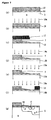
- FIG 3 shows cross sectional views explaining the steps 3(a) through 3(e) for manufacturing the IGBT of Figure 1.
- Figure 3 only the emitter side of the IGBT is shown for the sake of simplicity.
- a thin gate oxide film 10 is formed on n-type drift layer 3 by thermal oxidation.
- a polycrystalline silicon film is deposited on gate oxide film 10 by the vacuum CVD method.
- gate electrode 7 is formed by patterning the deposited polycrystalline silicon film by photolithography.
- boron ions 14a are implanted using a patterned photoresist 11 on gate electrode 7 as a mask under an acceleration voltage high enough to make boron ions 14a penetrate through gate electrode 7.
- the implanted boron atoms are designated by a reference numeral 14b.
- the boron ions are implanted shallowly through gate electrode 7.
- the dose amount is, for example, 5X10 13 /cm 3 , that is smaller than the dose amount for the conventional manufacturing process explained with reference to Figure 11.
- boron ions 15a are implanted using a patterned photoresist 12 for forming p + -type contact region 5.
- the implanted boron atoms are designated by a reference numeral 15b.
- arsenic ions 16a are implanted using gate electrode 7 and a patterned photoresist 13 as masks for forming n-type emitter region 6 (under a low acceleration voltage).
- the implanted arsenic atoms are designated by a reference numeral 16b.
- p-type well region 4a, p + -type contact region 5 and n-type emitter region 6 are formed by activating the implanted boron atoms 14b and 15b and the implanted arsenic atoms 16b by a heat treatment.
- p-type well region 4a and n-type emitter region 6 are not perfectly self-aligned.
- p-type well region 4a and n-type emitter region 6 may be half self-aligned based on that the spacing between the edge of p-type well region 4a and the edge of n-type emitter region 6 is determined by the thickness of photoresist 11 and the acceleration voltage for implanting boron ions 14a. The offset length is observable visually after patterning.
- the diffusion depth is 1.5 ⁇ m for p-type well region 4a, 3 ⁇ m for p + -type contact region 5 and 0.3 ⁇ m for n-type emitter region 6.
- the offset length of p-type well region 4a is 1 ⁇ m. Since the channel length for the self-aligned p-type well region 4 and n-type emitter region 6 is about 0.4 ⁇ m, the channel length in the IGBT according to the first embodiment is about 1.4 ⁇ m.
- Figure 4 shows a pair of curves comparing the voltage dependence of the collector current in the load short-circuit at the diffusion depth of p-type well region 4a of 1.5 ⁇ m and the offset length of 1 ⁇ m in the IGBT exhibiting the breakdown voltage of the 600 V class with that of the conventional IGBT having the same channel length.
- the load short-circuit current at the collector voltage of 400 V is 1650 A/cm 2 for the present IGBT, that is less than half the load short-circuit current of 3700 A/cm 2 for the conventional IGBT.
- Figure 5 shows a pair of curves relating the collector current with the collector voltage for the IGBT according to the first embodiment and the conventional IGBT.
- the on-voltage of the IGBT according to the first embodiment is lower than the on-voltage of the conventional IGBT.
- the lower on-voltage is realized by the JFET component reduced by diffusing p-type well region 4a more shallowly than p + -type contact region 5.
- Figure 6 shows a pair of curves relating the on-voltage and the short-circuit current with the offset length at the same diffusion depth of the p-type well region.
- the on-voltage is low at the offset length of less than 0.5 ⁇ m, the load short-circuit current is too large. At the offset length of 0.5 ⁇ m or more, the load short-circuit current is small enough to obtain the desired short circuit withstand capability of 10 ⁇ sec or more. Although the load short-circuit current is small at the offset length of more than 5.0 ⁇ m, the on-voltage is more than 3.0 V, that is practically too high.
- steps 3(a) through 3(e) are not the only solution for manufacturing the IGBT according to the invention.
- the step 3(b) and the step 3(c) are interchangeable.
- Various variations are possible within the scope of the invention.
- Figure 7 shows cross sectional views explaining the steps 7(a) through 7(g) for manufacturing an IGBT according to a second embodiment of the invention.
- Figure 7 only the emitter side of the IGBT is shown for the sake of simplicity.
- a thin gate oxide film 10 is formed on n-type drift layer 3 by thermal oxidation.
- a polycrystalline silicon film 18 is deposited on gate oxide film 10 by the CVD method.
- boron ions 18a are implanted in polycrystalline silicon film 18 under an acceleration voltage low enough to stop the implanted boron atoms within the surface portion of polycrystalline silicon film 18 so that a damaged layer may be formed in the surface portion of polycrystalline silicon film 18.
- Other ions may be used in substitution for the boron ions for forming the damaged layer.
- a photoresist 11 is coated on polycrystalline silicon film 18. After patterning photoresist 11, a gate electrode 7 is formed by etching polycrystalline silicon film 18. Since the damaged layer is etched more quickly, gate electrode 7 has a cross section as shown in the figure.
- boron ions 14a are implanted using gate electrode 7 as a mask under an acceleration voltage high enough to make the boron ions penetrate through the thin portion of gate electrode 7.
- the implanted boron atoms are designated by a reference numeral 14b.
- boron ions 15a are implanted using gate electrode 7 as a mask under a low acceleration voltage.
- the implanted boron atoms are designated by a reference numeral 15b.
- arsenic ions 16a are implanted using gate electrode 7 and a patterned photoresist 12 as masks under a low acceleration voltage.
- the implanted arsenic atoms are designated by a reference numeral 16b.
- a p-type well region 4a, a p + -type contact region 5 and an n-type emitter region 6 are formed by activating implanted boron atoms 14b and 15b and implanted arsenic atoms 16b by a heat treatment.
- p-type well region 4a and n-type emitter region 6 are half self-aligned by the manufacturing method according to the second embodiment, since the edge of p-type well region 4a and the edge of n-type emitter region 6 are displaced by the slant angle determined by the etching speed of the damaged layer in polycrystalline silicon film 18.
- p-type well region 4a having an offset portion and n-type emitter region 6 are formed with excellent reproducibility without changing the conventional manufacturing process so much.
- Figure 8 is a cross sectional view of the unit structure (half cell) of a trench-type IGBT according to a third embodiment of the invention.
- a p-type well region 34 is in the surface portion of an n-type drift layer 33.
- An n-type emitter region 36 is in p-type well region 34.
- a heavily doped p + -type contact region 35 is in the surface portion of p-type well region 34.
- a trench 41 is dug from the surface of n-type emitter region 36 down to n-type drift layer 33.
- a gate electrode 37 is buried in trench 41 with a gate oxide film 40 interposed therebetween.
- An emitter electrode 39 is in common contact with n-type emitter region 36 and p + -type contact region 35.
- a p-type collector layer 32 is on the back surface of n-type drift layer 33.
- a collector electrode 31 is on p-type collector layer 32.
- the thickness of p-type well region 34 facing to trench 41 is the channel length.
- Figure 9 shows a pair of curves relating the on-voltage and the short-circuit current with the channel length in the trench-type IGBT of Figure 8.
- the on-voltage is low at the channel length of less than 8 ⁇ m, the load short-circuit current is too large. At the channel length of 8 ⁇ m or more, the load short-circuit current is small enough to obtain the desired short circuit withstand capability of 10 ⁇ sec or more. Although the load short-circuit current is small at the channel length of more than 20 ⁇ m, the on-voltage is more than 3.0 V, that is practically too high.
- the invention is applicable to MOSFETs by changing the emitter and the collector to a source and a drain, respectively.
- the invention is applicable also to insulated gate thyristors.
- the parasitic JFET effect is suppressed and the load short-circuit current is reduced by controlling the diffusion depth of the well region of the second conductivity type and the channel length independently.
- the on-voltage of the insulated gate transistor is reduced by the suppression of the parasitic JFET effect and the short circuit withstand capability thereof is improved by the reduction of the load short-circuit current.
- the present invention facilitates reducing the loss of the power devices for high power use and improving the efficiency of the electric power conversion apparatuses.
Landscapes
- Thyristors (AREA)
- Bipolar Transistors (AREA)
- Insulated Gate Type Field-Effect Transistor (AREA)
Applications Claiming Priority (2)
| Application Number | Priority Date | Filing Date | Title |
|---|---|---|---|
| JP18989199 | 1999-07-05 | ||
| JP11189891A JP2001024184A (ja) | 1999-07-05 | 1999-07-05 | 絶縁ゲートトランジスタおよびその製造方法 |
Publications (2)
| Publication Number | Publication Date |
|---|---|
| EP1067607A2 true EP1067607A2 (de) | 2001-01-10 |
| EP1067607A3 EP1067607A3 (de) | 2003-08-06 |
Family
ID=16248922
Family Applications (1)
| Application Number | Title | Priority Date | Filing Date |
|---|---|---|---|
| EP00305417A Withdrawn EP1067607A3 (de) | 1999-07-05 | 2000-06-28 | Transistor mit isoliertem Gate und Verfahren zur Herstellung |
Country Status (3)
| Country | Link |
|---|---|
| US (1) | US6501128B1 (de) |
| EP (1) | EP1067607A3 (de) |
| JP (1) | JP2001024184A (de) |
Cited By (1)
| Publication number | Priority date | Publication date | Assignee | Title |
|---|---|---|---|---|
| CN106876445A (zh) * | 2017-03-23 | 2017-06-20 | 深圳基本半导体有限公司 | 一种大功率平面栅d‑mosfet结构设计 |
Families Citing this family (11)
| Publication number | Priority date | Publication date | Assignee | Title |
|---|---|---|---|---|
| JP4371521B2 (ja) * | 2000-03-06 | 2009-11-25 | 株式会社東芝 | 電力用半導体素子およびその製造方法 |
| JP2002305304A (ja) * | 2001-04-05 | 2002-10-18 | Toshiba Corp | 電力用半導体装置 |
| US8389366B2 (en) | 2008-05-30 | 2013-03-05 | Freescale Semiconductor, Inc. | Resurf semiconductor device charge balancing |
| JP5239548B2 (ja) * | 2008-06-25 | 2013-07-17 | 富士通セミコンダクター株式会社 | 半導体装置及び半導体装置の製造方法 |
| CN101710586B (zh) * | 2009-01-09 | 2011-12-28 | 深超光电(深圳)有限公司 | 提高开口率的储存电容及其制作方法 |
| JP6700648B2 (ja) | 2012-10-18 | 2020-05-27 | 富士電機株式会社 | 半導体装置の製造方法 |
| CN103973277B (zh) | 2013-02-05 | 2017-06-09 | 通用电气公司 | 绝缘栅双极型晶体管的短路保护电路和方法 |
| JP6182921B2 (ja) | 2013-03-21 | 2017-08-23 | 富士電機株式会社 | Mos型半導体装置 |
| JP2015041644A (ja) * | 2013-08-20 | 2015-03-02 | 富士電機株式会社 | Mos型半導体装置の製造方法 |
| US11309413B2 (en) * | 2019-10-10 | 2022-04-19 | Wolfspeed, Inc. | Semiconductor device with improved short circuit withstand time and methods for manufacturing the same |
| CN111430449B (zh) * | 2020-04-01 | 2023-06-02 | 清纯半导体(宁波)有限公司 | 一种mosfet器件及其制备工艺 |
Family Cites Families (18)
| Publication number | Priority date | Publication date | Assignee | Title |
|---|---|---|---|---|
| US4672407A (en) | 1984-05-30 | 1987-06-09 | Kabushiki Kaisha Toshiba | Conductivity modulated MOSFET |
| US5173435A (en) * | 1987-11-11 | 1992-12-22 | Mitsubishi Denki Kabushiki Kaisha | Insulated gate bipolar transistor |
| JPH0734474B2 (ja) * | 1988-03-03 | 1995-04-12 | 富士電機株式会社 | 伝導度変調型mosfetの製造方法 |
| JPH0687504B2 (ja) | 1988-04-05 | 1994-11-02 | 株式会社東芝 | 半導体装置 |
| JPH02163974A (ja) * | 1988-12-16 | 1990-06-25 | Mitsubishi Electric Corp | 絶縁ゲート型バイポーラトランジスタおよびその製造方法 |
| JPH02281662A (ja) * | 1989-04-21 | 1990-11-19 | Mitsubishi Electric Corp | 半導体装置 |
| US5151762A (en) * | 1990-04-12 | 1992-09-29 | Mitsubishi Denki Kabushiki Kaisha | Semiconductor device, fabricating method thereof and flash control device using the semiconductor device |
| JP2751612B2 (ja) * | 1990-10-01 | 1998-05-18 | 株式会社デンソー | 縦型パワートランジスタ及びその製造方法 |
| JPH05160407A (ja) * | 1991-12-09 | 1993-06-25 | Nippondenso Co Ltd | 縦型絶縁ゲート型半導体装置およびその製造方法 |
| JP2561413B2 (ja) * | 1993-02-23 | 1996-12-11 | 日産自動車株式会社 | 半導体装置 |
| US5723890A (en) * | 1994-01-07 | 1998-03-03 | Fuji Electric Co., Ltd. | MOS type semiconductor device |
| US5701023A (en) * | 1994-08-03 | 1997-12-23 | National Semiconductor Corporation | Insulated gate semiconductor device typically having subsurface-peaked portion of body region for improved ruggedness |
| JP3141769B2 (ja) * | 1996-02-13 | 2001-03-05 | 富士電機株式会社 | 絶縁ゲート型サイリスタ及びその製造方法 |
| JP3209091B2 (ja) * | 1996-05-30 | 2001-09-17 | 富士電機株式会社 | 絶縁ゲートバイポーラトランジスタを備えた半導体装置 |
| US6037628A (en) * | 1997-06-30 | 2000-03-14 | Intersil Corporation | Semiconductor structures with trench contacts |
| JP3424579B2 (ja) * | 1998-02-27 | 2003-07-07 | 株式会社豊田中央研究所 | 半導体装置 |
| US6303410B1 (en) * | 1998-06-01 | 2001-10-16 | North Carolina State University | Methods of forming power semiconductor devices having T-shaped gate electrodes |
| JP3460585B2 (ja) * | 1998-07-07 | 2003-10-27 | 富士電機株式会社 | 炭化けい素mos半導体素子の製造方法 |
-
1999
- 1999-07-05 JP JP11189891A patent/JP2001024184A/ja active Pending
-
2000
- 2000-06-28 EP EP00305417A patent/EP1067607A3/de not_active Withdrawn
- 2000-07-05 US US09/610,052 patent/US6501128B1/en not_active Expired - Lifetime
Cited By (1)
| Publication number | Priority date | Publication date | Assignee | Title |
|---|---|---|---|---|
| CN106876445A (zh) * | 2017-03-23 | 2017-06-20 | 深圳基本半导体有限公司 | 一种大功率平面栅d‑mosfet结构设计 |
Also Published As
| Publication number | Publication date |
|---|---|
| US6501128B1 (en) | 2002-12-31 |
| EP1067607A3 (de) | 2003-08-06 |
| JP2001024184A (ja) | 2001-01-26 |
Similar Documents
| Publication | Publication Date | Title |
|---|---|---|
| EP2333839B1 (de) | Bipolartransistor mit isoliertem Gate und Verfahren zu dessen Herstellung | |
| US6297104B1 (en) | Methods to produce asymmetric MOSFET devices | |
| US5341011A (en) | Short channel trenched DMOS transistor | |
| US8592894B2 (en) | Method of forming a power semiconductor device and power semiconductor device | |
| US7968940B2 (en) | Insulated gate bipolar transistor device comprising a depletion-mode MOSFET | |
| JP2932429B2 (ja) | Mos電界効果トランジスタ及びその製造方法 | |
| US5434435A (en) | Trench gate lateral MOSFET | |
| US7569900B2 (en) | Silicon carbide high breakdown voltage semiconductor device | |
| JP2942732B2 (ja) | 短絡アノード水平型絶縁ゲートバイポーラトランジスタ | |
| JP2004537162A (ja) | パワーデバイスとその製造方法 | |
| JP2004006598A (ja) | 絶縁ゲート型半導体装置 | |
| US6501128B1 (en) | Insulated gate transistor and the method of manufacturing the same | |
| JPH09503626A (ja) | 高いラッチアップ耐性を備えた炭化ケイ素ベースのmis構造 | |
| JP2003101019A (ja) | 半導体装置及びその製造方法 | |
| JP3409244B2 (ja) | 半導体装置 | |
| JP2002217406A (ja) | 半導体装置とその製造方法 | |
| KR100902848B1 (ko) | 고전압용 절연 게이트 양극성 트랜지스터 및 그 제조방법 | |
| JPH1140808A (ja) | 半導体装置およびその製造方法 | |
| CN101770949B (zh) | 用于制造功率半导体器件的方法 | |
| JP2003338624A (ja) | 半導体装置 | |
| KR100910798B1 (ko) | 불순물 주입층이 형성된 트랜치를 가지는 고전압용 트랜치절연 게이트 양극성 트랜지스터 및 그 제조방법 | |
| JP7750312B2 (ja) | 半導体装置および半導体装置の製造方法 | |
| US8217448B2 (en) | Semiconductor device and method of forming a semiconductor device | |
| US8188539B2 (en) | Field-effect semiconductor device and method of forming the same | |
| JPH10229192A (ja) | 半導体スイッチ素子 |
Legal Events
| Date | Code | Title | Description |
|---|---|---|---|
| PUAI | Public reference made under article 153(3) epc to a published international application that has entered the european phase |
Free format text: ORIGINAL CODE: 0009012 |
|
| AK | Designated contracting states |
Kind code of ref document: A2 Designated state(s): AT BE CH CY DE DK ES FI FR GB GR IE IT LI LU MC NL PT SE |
|
| AX | Request for extension of the european patent |
Free format text: AL;LT;LV;MK;RO;SI |
|
| PUAL | Search report despatched |
Free format text: ORIGINAL CODE: 0009013 |
|
| AK | Designated contracting states |
Designated state(s): AT BE CH CY DE DK ES FI FR GB GR IE IT LI LU MC NL PT SE |
|
| AX | Request for extension of the european patent |
Extension state: AL LT LV MK RO SI |
|
| AKX | Designation fees paid | ||
| REG | Reference to a national code |
Ref country code: DE Ref legal event code: 8566 |
|
| STAA | Information on the status of an ep patent application or granted ep patent |
Free format text: STATUS: THE APPLICATION IS DEEMED TO BE WITHDRAWN |
|
| 18D | Application deemed to be withdrawn |
Effective date: 20040207 |