EP1048953A2 - Methode et dispositif pour transferer les liquides dans un appareil d'analyse - Google Patents
Methode et dispositif pour transferer les liquides dans un appareil d'analyse Download PDFInfo
- Publication number
- EP1048953A2 EP1048953A2 EP00107965A EP00107965A EP1048953A2 EP 1048953 A2 EP1048953 A2 EP 1048953A2 EP 00107965 A EP00107965 A EP 00107965A EP 00107965 A EP00107965 A EP 00107965A EP 1048953 A2 EP1048953 A2 EP 1048953A2
- Authority
- EP
- European Patent Office
- Prior art keywords
- liquid
- liquid transfer
- cannula
- electrode
- tip
- Prior art date
- Legal status (The legal status is an assumption and is not a legal conclusion. Google has not performed a legal analysis and makes no representation as to the accuracy of the status listed.)
- Granted
Links
Images


Classifications
-
- G—PHYSICS
- G01—MEASURING; TESTING
- G01N—INVESTIGATING OR ANALYSING MATERIALS BY DETERMINING THEIR CHEMICAL OR PHYSICAL PROPERTIES
- G01N35/00—Automatic analysis not limited to methods or materials provided for in any single one of groups G01N1/00 - G01N33/00; Handling materials therefor
- G01N35/10—Devices for transferring samples or any liquids to, in, or from, the analysis apparatus, e.g. suction devices, injection devices
- G01N35/1009—Characterised by arrangements for controlling the aspiration or dispense of liquids
- G01N35/1016—Control of the volume dispensed or introduced
-
- G—PHYSICS
- G01—MEASURING; TESTING
- G01F—MEASURING VOLUME, VOLUME FLOW, MASS FLOW OR LIQUID LEVEL; METERING BY VOLUME
- G01F23/00—Indicating or measuring liquid level or level of fluent solid material, e.g. indicating in terms of volume or indicating by means of an alarm
- G01F23/22—Indicating or measuring liquid level or level of fluent solid material, e.g. indicating in terms of volume or indicating by means of an alarm by measuring physical variables, other than linear dimensions, pressure or weight, dependent on the level to be measured, e.g. by difference of heat transfer of steam or water
- G01F23/24—Indicating or measuring liquid level or level of fluent solid material, e.g. indicating in terms of volume or indicating by means of an alarm by measuring physical variables, other than linear dimensions, pressure or weight, dependent on the level to be measured, e.g. by difference of heat transfer of steam or water by measuring variations of resistance of resistors due to contact with conductor fluid
- G01F23/245—Indicating or measuring liquid level or level of fluent solid material, e.g. indicating in terms of volume or indicating by means of an alarm by measuring physical variables, other than linear dimensions, pressure or weight, dependent on the level to be measured, e.g. by difference of heat transfer of steam or water by measuring variations of resistance of resistors due to contact with conductor fluid with a probe moved by an auxiliary power, e.g. meter, to follow automatically the level
-
- G—PHYSICS
- G01—MEASURING; TESTING
- G01F—MEASURING VOLUME, VOLUME FLOW, MASS FLOW OR LIQUID LEVEL; METERING BY VOLUME
- G01F23/00—Indicating or measuring liquid level or level of fluent solid material, e.g. indicating in terms of volume or indicating by means of an alarm
- G01F23/22—Indicating or measuring liquid level or level of fluent solid material, e.g. indicating in terms of volume or indicating by means of an alarm by measuring physical variables, other than linear dimensions, pressure or weight, dependent on the level to be measured, e.g. by difference of heat transfer of steam or water
- G01F23/26—Indicating or measuring liquid level or level of fluent solid material, e.g. indicating in terms of volume or indicating by means of an alarm by measuring physical variables, other than linear dimensions, pressure or weight, dependent on the level to be measured, e.g. by difference of heat transfer of steam or water by measuring variations of capacity or inductance of capacitors or inductors arising from the presence of liquid or fluent solid material in the electric or electromagnetic fields
- G01F23/263—Indicating or measuring liquid level or level of fluent solid material, e.g. indicating in terms of volume or indicating by means of an alarm by measuring physical variables, other than linear dimensions, pressure or weight, dependent on the level to be measured, e.g. by difference of heat transfer of steam or water by measuring variations of capacity or inductance of capacitors or inductors arising from the presence of liquid or fluent solid material in the electric or electromagnetic fields by measuring variations in capacitance of capacitors
-
- G—PHYSICS
- G01—MEASURING; TESTING
- G01N—INVESTIGATING OR ANALYSING MATERIALS BY DETERMINING THEIR CHEMICAL OR PHYSICAL PROPERTIES
- G01N35/00—Automatic analysis not limited to methods or materials provided for in any single one of groups G01N1/00 - G01N33/00; Handling materials therefor
- G01N35/10—Devices for transferring samples or any liquids to, in, or from, the analysis apparatus, e.g. suction devices, injection devices
- G01N35/1009—Characterised by arrangements for controlling the aspiration or dispense of liquids
- G01N35/1016—Control of the volume dispensed or introduced
- G01N2035/1018—Detecting inhomogeneities, e.g. foam, bubbles, clots
-
- G—PHYSICS
- G01—MEASURING; TESTING
- G01N—INVESTIGATING OR ANALYSING MATERIALS BY DETERMINING THEIR CHEMICAL OR PHYSICAL PROPERTIES
- G01N35/00—Automatic analysis not limited to methods or materials provided for in any single one of groups G01N1/00 - G01N33/00; Handling materials therefor
- G01N35/10—Devices for transferring samples or any liquids to, in, or from, the analysis apparatus, e.g. suction devices, injection devices
- G01N35/1009—Characterised by arrangements for controlling the aspiration or dispense of liquids
- G01N2035/1025—Fluid level sensing
Definitions
- the invention relates to a liquid transfer device for an analyzer with a liquid transfer cannula and a capacitive liquid level detector for the detection of the immersion of the liquid transfer cannula into an analysis liquid in a vessel, the liquid level detector a signal electrode, a counter electrode and a detection circuit to detect a change in capacity between the signal electrode and the counter electrode, and a corresponding control procedure sucking analysis liquid into a liquid transfer cannula and a suitably trained Liquid transfer cannula.
- liquid transfer devices are needed to Analysis liquids, especially liquid samples or Reagents to transfer.
- Common liquid transfer devices are, for example, pipettors, which are used for samples or reagents aspirate from a first vessel and into a second vessel eject, as well as dispensers where the liquid transfer cannula via a hose to a larger one Supply of a liquid that is connected with Ejected through the cannulas with the aid of a pump device can be.
- Dispensers usually also fulfill that Pipette function.
- liquid transfer device in the To view any device within the meaning of the present invention, which is used in an analysis device in an analysis liquid to immerse yourself in any liquid transfer steps (Suction and / or discharge of Liquid) by means of the liquid transfer cannula enable.
- the liquid transfer cannula is for example a hollow needle, which usually consists of a thin Pipe made of metal or plastic. she will hereinafter also referred to as “cannula” for the sake of simplicity.
- Other known embodiments are single use Dispensing tips that are disposed of after use and be replaced by new ones. You can use a tubular one or conical shape, optionally with a having a cross section that changes like a nozzle Metal or plastic, for example a conductive one Plastic, are and will also be in the following referred to as "cannula".
- the immersion depth Liquid transfer devices with a sensor device to detect the immersion of the cannula in the Provide analysis liquid, commonly used as a liquid level detector or LLD (liquid level detector) referred to as.
- the liquid level detector is with the vertical drive through which the cannula into the Analysis liquid is immersed, connected to the Stop immersion when the tip of the cannula immersed in the analysis liquid by a few millimeters is. It is not just the problem of procrastination to be observed, but at the same time also be ensured that no air is sucked in, leading to could lead to diagnostically relevant measurement errors. Out for this reason, a minimum immersion depth must be observed, which can be between 0.1 mm and 5 mm.
- the vertical position of the cannula is also a Measure of the level of the liquid in the respective Vessel.
- the liquid level detector enables at the same time controlling the in each Vessel amount of liquid present, for example to give a signal when the supply of a reagent liquid is used up and therefore the reagent bottle must be replaced.
- a common design principle for liquid level detectors is based on the electrical Resistance between the cannula and one at the tip of the electrode attached to the cannula.
- Cannula and Electrode are electrically isolated from each other, so that the electrical resistance between them in the dry Condition is very high.
- the sample liquid forms a conductive connection, so that the electrical resistance leaps and bounds changes.
- This signal can be done with simple electronic Proof of means reliably.
- this principle can be seen in the fact that in addition to the Cannula must immerse an electrode in the liquid, on which an excess liquid is inevitably attached remains. This addresses the aforementioned problems Carryover and reduced accuracy additionally enlarged unless disposable dispensing tips are used become.
- Capacitive liquid level detectors are superior in this respect, where as a signal for detection of immersing the cannula in the liquid Change in electrical capacity between two sensor electrodes by means of an electronic detection circuit, which includes an AC voltage source becomes.
- the first electrode is usually the cannula itself (which is made of metal or an electrical conductive (metallized) plastic) and to which the hot pole of the AC voltage source is connected is (signal electrode).
- the counter electrode which is usually at ground potential, is in the known Devices on the outside of the liquid container (under the floor and partly around the side walls around the vessel). It is common a component of the vessel holder. When immersing the cannula tip into the liquid changes the capacity between the signal electrode and the counter electrode due to the electrical conductivity and the dielectric properties of the liquid.
- a fundamental problem of capacitive liquid level detectors is that the capacity change when immersed in the liquid is very small compared to the other inevitably existing Capacities ("interference capacities", e.g. of the connection cable and the amplifier input). As a result, the relationship very unfavorable between useful signal and interference signals. It is particularly problematic that part of the Interference capacities is not constant, but changes over time changes relatively quickly. This is especially true for capacitive disturbances caused by the movement of Objects (components of the analyzer, hands or other parts of the operator's body) become. Especially on a fully automated analyzer, which has numerous moving parts are such Unavoidable interference in practice.
- EP-A-0 355 791 addresses a specific such problem (Disturbances due to a membrane closing the vessel) fixed that a reference signal at the Contacting the membrane fixed and at the next Downward movement of the cannula is the difference to this fixed reference signal is detected.
- This method is geared towards the special application. Interference capacities between the fixation of the Reference signal and the detection of the liquid surface change lead to incorrect detection.
- a liquid transfer device for an analyzer with an improved liquid level detector Failure safety and more reliable function is known from document EP 0555710 A2.
- the coaxial electrode assembly including the liquid transfer cannula proposed an active shield by means of a compensation electrode attached to a voltage follower circuit is connected.
- an additional shielding electrode that acts as a counter electrode and is at constant potential, to provide.
- the high sensitivity also disadvantageous in the area of the tip of the cannula can be as any moisture film in the area as the tip Surface of a compact, solid liquid is detected will, even if the tip of the cannula covers the surface has not yet reached the liquid.
- This can avoid special, elaborate error strategies developed and used, for example descendants, multiple plunging, pressure measurement or plausibility checks at a predictable level.
- a falsifying the detection of the liquid surface Liquid film can in particular the formation of Foam or of structures similar to soap bubbles, which are relatively durable and also by piercing the Cannula are not necessarily destroyed.
- Foam layers or structures similar to soap bubbles arise, for example, when shaking whole blood samples, when centrifuging blood samples during serum plasma collection, when transporting reagent rack packs and when Resuspend and stir so-called with streptavidin coated beads.
- foam layers are in usually 2 to 5 mm thick. Also on the container collar In many cases, bubbles cannot form stab the thin cannula.
- Constipation also known as clots
- Constipation also known as clots
- the one with an additional Vacuum measurement associated equipment effort for detection however, such error is relatively high.
- a special complex process for checking the dosage is an immunology analyzer for blood banks known in which each metering process by means of a video camera and an image processing is controlled.
- a liquid level detector is known from document US 5,045,286 known in which the immersion of the cannula tip into the liquid through one at the bottom conductivity measurement carried out at the tip becomes.
- this process is relatively slow and can when immersing the tip in foam on the Forms a conductive film on the outside of the tip Incorrect doses cause the system does not recognize that no liquid is sucked in.
- a capacitive liquid level detector is known from document US Pat. No. 5,855,851 known in the field of Cannula tip has an additional conductivity measurement.
- the conductivity measurement will be slightly above of the lower end of the tip on the outside, to check if the tip is too deep in liquid has been immersed and needs to be washed.
- This known device cannot be recognized whether air bubbles were sucked into the cannula, but just whether there is any unwanted liquid on the outside located.
- the invention has for its object the known capacitive liquid level detectors, in particular the triaxial known from document EP 0555710 A2 Arrangement with actively shielded compensation electrode and entrained shield electrode acting as a counter electrode to develop in such a way that error-free between compact solid liquid and foam or Liquid films can be distinguished and also at small dosing volume can be checked whether air or liquid has been sucked in.
- the task is at a liquid transfer facility of the type described at the beginning with a capacitive Liquid level detector solved in that the Liquid transfer cannula has two control electrodes, between which a detection path is formed is, the control electrodes are arranged such that the detection path predominantly inside the liquid transfer cannula runs, at least one of the control electrodes at a distance above the lower end the tip of the liquid transfer cannula and the detection circuit is a control device includes that to control yourself when filling the Detection distance in the liquid transfer cannula with Analysis fluid resulting change in resistance the detection path is formed.
- the idea on which the invention is based is that to check if the cannula is in the analysis liquid is immersed, or to check whether air or Liquid is sucked into the liquid transfer cannula was the electrical resistance or corresponding to the electrical conductance of a detection path is detected that is in the fluid channel of the liquid transfer cannula lies and with correct functioning with analysis liquid fills.
- a detection route in this sense is so a conductive path through analytical fluid that is in the cannula.
- Such a current path can be linear or spatial as a detection zone, where the beginning and the end or the poles by the both control electrodes are given.
- the electrical conductivity of analysis liquid higher than that of air can be controlled in this way be whether the detection path by air or runs through analysis liquid. If according to the invention the detection path predominantly inside the cannula runs and at least one of the control electrodes above the lower end of the tip of the cannula is ensured that the control device Immersion of the cannula in foam can be recognized because of the Foam does not lead to a greatly increased conductivity Detection path can lead. The detection path can thus be drawn to one of the capacitive Liquid level detector detected immersion in to check and verify a liquid and order detect the suction of air into the cannula.
- the conductivity would be checked Analysis liquid by means of the detection section alone, i.e. without combination with a capacitive liquid level detector, for the detection of immersion into the analysis liquid and to recognize Suitable for air bubbles.
- a capacitive liquid level detector for the detection of immersion into the analysis liquid and to recognize Suitable for air bubbles.
- Such a structure is, however, in the most applications too slow to match the speed of detection to meet the requirements.
- the combination of a fast reacting capacitive liquid level detection with a slower follow - up check using the Detection distance are the advantages of both detection options united.
- a qualitative control of the Liquid transfers with the cannula through monitoring the resistance of the detection path when sucking in as well as when dispensing liquid.
- Multiple pipetting can be carried out individually in the cannula sucked in liquid sections separated by separation bubbles be identified because the separation bubbles change the resistance of the detection path.
- a quantitative control of fluid transfer can be carried out when the dosing rate, with the analysis liquid is sucked in or ejected, known is and until the resistance of the detection path changes elapsing time is measured.
- a defect in the cannula, sucking in air, clogging the fluid channel (through so-called clots) or that This allows the dosing cannula to be placed on the bottom of the vessel can be recognized that no analysis liquid Detection path reaches or fills and their resistance does not change.
- the invention thus has the advantage on that it is possible to have a qualitative dosage control to carry out, it being checked whether analytical liquid sucked into or through the cannula was delivered. There is also a quantitative dosage control of the transferred analysis liquid possible. Another advantage is that it is reliable Foam is detected and the surface of the analysis liquid can be safely detected, so that a correct Liquid transfer is made possible. It is not elaborate vacuum measurement required to prevent clogging register the dispensing needle. With the invention goals are achieved by which the professional community has been trying for a long time.
- liquid transfer cannula in particular the needle tip, one of the control electrodes.
- the cannula forms one of the control electrodes the constructive effort to manufacture and, if necessary also the technical effort for measuring the resistance the detection distance is reduced.
- the Control electrode by appropriate design of the supply lines and the materials of the cannula be placed anywhere in the cannula. Especially It is advantageous if the tip is a control electrode forms, since this ensures that the detection path runs close to the tip.
- Another advantageous feature can be that the detection path at such a distance above the lower one End of the tip is arranged so that it does not dip the liquid transfer cannula into the analysis liquid, but only when sucking in analysis liquid into the liquid transfer cannula completely runs through analysis liquid.
- This is a targeted Control of fluid transfer through the in Analytical liquid immersed liquid transfer cannula possible because the detection distance between the control electrodes only when sucking in analysis liquid changes the resistance.
- the detection path extends over the entire height of the cannula. It is for Allowing control of the smallest possible dosing volume even desirable that the detection path over the smallest possible height section of the cannula extends and not too far from the top is.
- the lower end of the detection path above the lower end of the cannula tip is arranged. This makes it possible to put the cannula in immerse the analysis liquid slightly without which the lower control electrode is wetted or which Detection section already reacts to analysis liquid, so that the suction of air bubbles is reliably recognized can be.
- the lower end of the detection path is preferably between 0.5 mm and 5 mm above the arranged at the bottom of the tip.
- the detection path is arranged in the area of the tip, so that not much analysis liquid is in the liquid transfer cannula until a change in resistance occurs the detection path must be sucked in.
- the upper end of the detection path in Area of the tip preferably between 0.5 mm and 30 mm is located above the lower end of the tip.
- a detection path in combination with a capacitive Liquid level detector is in principle with advantageous for all capacitive liquid level detectors, regardless of whether with these the capacity the liquid transfer cannula is measured against mass or the liquid transfer cannula is part of a Coaxial electrode arrangement is.
- General is a control always advantageous by means of a detection path, if the capacitive liquid level detector is designed to be very sensitive to Capacity changes in the environment (samples, rotor, Test tubes, static charges etc.) reacts and especially if he's very sensitive to capacity changes around the tip of the liquid transfer cannula responds.
- the control of the Detection section in practice no particular advantages provide in the detection of foam when the mass of detected liquid itself included in the signal path is because in this case the foaming or blistering hardly affects the detection of the liquid surface.
- the invention is therefore preferred for coaxial electrode arrangements according to document EP 0555710 A2, to the extent that full reference is made, i.e. in coaxial electrode arrangements, the advantageously a active shielding by means of a voltage follower circuit connected compensation electrode and / or one to the area of the tip of the liquid transfer cannula guided shielding electrode as counter electrode exhibit.
- a first preferred additional specialty can therefore consist in that the liquid transfer cannula part a coaxial electrode assembly which is in addition to the liquid transfer cannula at least one surrounding it and has coaxial electrode insulated therefrom.
- the coaxial electrode assembly is a shield electrode which surrounds the signal electrode Is constant potential and acts as a counter electrode.
- Another advantageous feature may be that Detection circuit an AC voltage source and a Has voltage follower circuit, and the input and Output of the voltage follower circuit with two neighboring ones Electrodes of the coaxial electrode arrangement as a signal electrode and compensation electrode are connected, so that between the signal electrode and the compensation electrode no voltage difference occurs and the capacity between the signal electrode and the compensation electrode is compensated. It can be done after another advantageous feature that a first the electrodes of the coaxial electrode arrangement the signal electrode of the liquid level detector and with is connected to the input of the voltage follower circuit and a second electrode of the coaxial electrode arrangement, which is adjacent to the signal electrode with which Output of the voltage follower circuit is connected.
- liquid transfer cannula as a signal electrode with the input the voltage follower circuit and the neighboring one Coaxial electrode as a compensation electrode with the output the voltage follower circuit is connected.
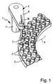
- the liquid transfer device shown in Figure 1 1 is used to remove an analysis liquid from one of the Remove tubes 2 and transfer them to another tube.
- the vessels 2 are located on a rotor 3 or another movable vessel holder.
- the vessel volumes are approx. 400 ⁇ l to 40 ml and the transferred amounts of liquid approx. 10-100 ⁇ l, with a resolution of approx. 0.25 ⁇ l.
- the liquids are in Microcuvettes ejected on an incubation rotor; the level must also be determined.
- a liquid transfer cannula 5 with an inner diameter of approx. 0.4 mm is on a movement device 6 attached, which one by means of a not shown Vertical drive up and down movable vertical column 7 and a swivel arm 8. This allows the Cannula 5 on the swivel circle 9 in different positions brought and lowered into one of the vessels 2.
- Such liquid transfer devices are in different Embodiments known.
- a suitable drive mechanism for example refer to EP-A-0 408 804.
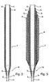
- Fig. 2 shows a cross section through a first invention Liquid transfer cannula 5, the needle-shaped is trained. It comprises two concentric ones Pipes 10, 11 made of metal or a conductive Consist of plastic and by means of an insulating material 12 are electrically isolated from each other. In the field of The tip 5a of the cannula 5, the tubes 10, 11 are tip-shaped pulled out, with the outer tube 10 at the bottom has a straight extension 13.
- the outer tube 10 forms the signal electrode of a capacitive Liquid level detector for detection immersing the cannula 5 in an analysis liquid.
- the lowering of the cannula 5 in the direction of an analysis liquid takes place with a motor drive.
- the capacitive liquid level detector makes the contact with a conductive medium.
- the drive moves a minimum immersion depth
- the connected dosing pump pulls by means of the auxiliary fluid located inside the cannula 5, that can be air or a system fluid, a certain volume from the analysis liquid.
- the lower end of the inner tube 11 ends above the lower end of the tip 5a of the cannula 5.
- the lower sections of inner tube 11 and outer tube 10 each form a control electrode 14, 15 between which a detection path 16 is formed.
- the control electrodes 14, 15 experience through absorbed analysis liquid a conductive connection that detects can be.
- the liquid transfer cannula 5 is preferably part of a Coaxial electrode arrangement 11.
- a coaxial electrode arrangement the electronic Circuit
- the advantages and possible alternatives and variants is based on the document EP 0555710 A2 and EP 0913671 A1.
- Coaxial electrode arrangement 18 of a liquid transfer cannula 5 comprises an active electrode as a compensation electrode Shielding coaxial electrode 19 and one of the Shielding counter electrode 20. Between the individual Electrodes there is insulating material 12, so far may be formed as a dielectric. The outside of the cannula 5 can be coated with a protective coating 21, which consist for example of insulating material can be coated.
- the outer tube 10 serving as a signal electrode is shown in radial direction on its entire circumference through the Compensation electrode 19 and the shielding electrode 20 surrounded and is in its spatial position relative to the Electrodes fixed.
- the coaxial electrode is therefore a fixed part of an axially extending over the predominant Length of the liquid transfer cannula 5, with the exception the tip 5a, extending coaxial electrode arrangement 18, so that no relative movement between the outer tube 10 and the electrodes surrounding it takes place.
- the compensation electrode 19, like the Shielding electrode 20, together with the liquid transfer cannula 5 up and down by means of a movement device moves the vessel with the analysis liquid downwards or vice versa towards the liquid transfer cannula 5 raised and lowered.
- the compensation electrode 19 Due to the active shielding by means of the compensation electrode 19 is in this relative movement between Liquid transfer cannula 5 and the analysis liquid the outer tube 10 serving as a signal electrode largely shielded so that not the entire cannula length capacitive to all conductive parts in their environment couples, but essentially the unshielded, at the bottom Outstanding tip on a short piece 5a. So there is only the capacity or a change the capacitance detects where it is for the capacitive Liquid level detection is appropriate.
- Their structure corresponds to that the cannula 5 shown in FIG. 2, with the difference that it tapered towards the top is. It comprises three concentric plastic layers, of which the outer 10 and inner 11 are conductive and the middle one consists of insulating material 12.
- the cannula 5 of FIG. 2 is included in the dosing System fluid 22 and an air bubble 23 shown.
- the detection path 16 can be recognized the system liquid 22 and the air bubble 23 and to control the absorption of analysis liquid be used.
- Fig. 6 where a foam bubble 24 sucked in from the foam 56 only to a low conductivity of the detection path 16 leads, so that the conductivity between the Control electrodes 14, 15 checking detection circuit can be seen that foam instead of analytical fluid was sucked in.
- FIG. 7 shows a basic circuit diagram of a detection circuit with a liquid transfer cannula 5, the corresponds to that of FIG. 3. Shown schematically is the movement device 6 with the associated control circuit 25, the two signals of a detection circuit 26 evaluates.
- the first signal 27 is that of the capacitive Liquid level detection and the second Signal 28 the signal of the dosing control by means of the Area of the tip 5a of the channels 5 arranged detection path 16.
- the cannula 5 is on via the hose 36 a dosing pump, not shown, is connected.
- the two switches 29 and 30 opened for capacitive liquid level detection not due to the low-resistance load resistor R2 to interfere with the conductivity measurement.
- the electrical connection to the inner tube 11 takes place capacitively and via influence or induction, i.e. inner tube 11 is electrically connected to outer tube 10 coupled.
- the cannula 5 When the cannula 5 is immersed, it changes Capacity at the tip 5a erratic, so that the Voltage across resistor R1 in terms of amplitude and phase changes. This change is made using the preamplifier 33, the phase rectifier 34 and the low pass 35 converted to DC voltage and as the first signal 27, the signal of the capacitive liquid level detection forms, the control circuit 25 supplied.
- the inner tube 11 with the second generator 32 Through the switch 29, the inner tube 11 with the second generator 32 connected.
- the second generator 32 generated to detect the conductivity of the detection path a significantly lower frequency than the first Generator 31; its frequency is about 1 kHz.
- the detection path 16 with a Resistor R2 loaded.
- the resistance R2 is approx. 1 k ⁇ . Due to the low frequency and low resistance R2, capacitive interference is negligible, i.e. the conductivity measurement is facilitated.
- the proportional to the conductivity of the detection section 16 Voltage drop across resistor R2 is determined using of the preamplifier 33, the phase rectifier 37 and of the low pass 38 is converted into a DC voltage, the as a second signal 28 for performing the dosing control is supplied to the control circuit 25. If the Detection section 16 a sufficiently large conductivity has, it means that analysis liquid is sucked in has been. Is the resistance of the detection path 16 on the other hand, after sucking in too high, there is an error condition before, for example sucking in air or Foam, blockage of the cannula 5 or a leak hose 36. To verify the fault condition, can then 5 gradually or continuously be positioned lower, taking in and checking the conductivity of the detection path 16 repeated regularly or continuously become.
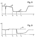
- a disturbance which results in a quick, short-term lowering of the signal.
- a disturbance can be caused, for example, by an electrostatic disturbance or a burst bubble.
- the lowering movement of the cannula 5 is not yet stopped by the short-term and rapid lowering of the signal, but instead, following this event, a query is made several times, for example three times, whether a certain value relative to the last measured reference value remains below this disturbance. If this is not the case, for example because the bubble has burst in the meantime and the tip 5a is therefore now in the air again, the downward movement continues because it was recognized that the tip 5a has not yet been immersed in the analysis liquid 4.
- the signal drops rapidly again and subsequently remains at the low value even during the multiple further scans 57.
- the tip 5a is either immersed in the analysis liquid 4 or is in a bubble or a foam over the analysis liquid 4, which have not receded due to the puncturing.
- this distinction which must be made within a very short time in order to prevent the liquid transfer cannula 5 from being immersed too deeply in the analysis liquid 4, cannot be made. Even if, for example, after three to four further polling intervals, the lowering movement is stopped and the possible evaluation conditions are fulfilled, i.e.
- Analysis liquid is drawn in at time t 3 . 9 that the resistance R of the detection path 16 drops. This is only the case if the detection path 16 actually runs through the sucked-in analysis liquid 4. In the event of a fault, for example a bubble not bursting, the signal would assume the alternative course 58 shown in dashed lines.
- a distinction can therefore be made as to whether or not the liquid transfer cannula 5, whose downward movement has been stopped at time t 2 or t 3 , is immersed in the analysis liquid 4 so that the liquid transfer begins or a new lowering movement can be initiated or this can be continued.
- the dosing cannula could be pulled out of the liquid, ejected liquid that had already been sucked up, and then the dosing cannula could be moved back into the previously found position in order to carry out the dosing.
- a variant of this which is particularly interesting for time-critical applications in which a very fast measurement is important and in which the time for the follow-up inspection by means of a detection section 16 before the liquid transfer is not available, is that the liquid transfer is already after the Stopping the immersion movement, ie at time t 3 , at which the capacitive post-checks are completed, and the check is carried out with the detection section 16 during the liquid transfer. If the resistance measurement shows that the liquid transfer cannula 5 had not yet been immersed in the analysis liquid at the time t 3 , this is signaled to the analysis system and the measurement result of the respective sample is subsequently rejected or the operator is immediately informed by a signal that there are problems with the dosage occur. In this way, a higher throughput rate can be achieved.
- control electrodes 14, 15 should be low-capacitance be to the capacitive liquid level detector not due to parasitic capacities to disturb. It is therefore proposed in an advantageous training that the control electrodes 14, 15 or at least a lead between a shielding electrode and a compensation electrode is arranged, the Capacity compensated by a voltage follower circuit becomes.
- the detection path 16 can also be between the signal electrode and a control electrode.
- the advantage here is that there are no separate supply lines to the detection path 16 because, for example the liquid transfer cannula, the shielding electrode or the coaxial electrode can be used as a lead can.
- the capacitive signal to be detected is therefore not subject to additional capacitive loads.
- control electrodes 14, 15 should be smooth, none Offer attack surface and mechanically fastened appropriately and be electronically connected. Maybe they can provided with a liquid-repellent nano-coating his. They can also be in a recess or opening in the area of the tip 5a or with be cast in a chemically resistant potting compound.
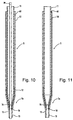
- Figures 10 and 11 illustrate the manufacture a cannula 5 according to FIG. 2.
- Prefabricated metal tubes 10, 11 are mounted concentrically to each other.
- a metal wire 39 which is almost the same diameter as the am lower end of the metal tubes 10, 11 arranged metering holes has, is through both metal tubes 10, 11th guided.
- the space 40 between the two metal pipes 10, 11 with meltable or sinterable, non-conductive Powder or granules filled.
- the metal wire 39 serves for the radial positioning of the metal pipes 10, 11 and prevents that in the space 40th filled material can penetrate into the dosing holes.
- the insulating material 12 forming the metal tubes 10, 11 are heated vertically.
- the hardened insulating material 12 extends to a predetermined one Height in the space 40.
- the space 40 need not be completely filled; in many applications it is sufficient if the lower ends the pipes 10, 11 fixed to each other by insulating material 12 without the gap 40 over its entire Height is filled.
- the metal wire pulled out so that a cannula 5 as shown in FIG. 11 is formed.
- the metal wire 39 can be stretched before pulling out which reduces its diameter. If necessary can additionally smooth the inside of the metering opening be, for example by honing or the like Method.
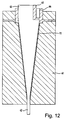
- Figures 12 to 15 illustrate the manufacture a liquid transfer cannula 5 in the form of a disposable dispensing tip as shown in FIG. 4. Three layers manufactured using a multi-component injection molding process.
- the mold 41 shows a mold 41 with an inserted therein customized mandrel 42.
- the inner, conductive Layer 11 by means of the sprue 43 in the cavity between Mold 41 and mandrel 42 injection molded, including a wiper 44 is formed.
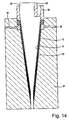
- the mandrel 42 becomes something pulled out of the mold 41 and the resulting Cavity becomes the formation as shown in Fig. 13 the insulating layer 12 through a further sprue 45 filled.
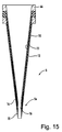
- the mandrel 42 is again slightly pulled out of the mold 41 and as shown in Figure 14, layer 10 of conductive Plastic injected through the sprue 46. After this The mold freezes and the finished cannula opens 5, which is shown in Fig. 15, stripped from the mandrel 42.
Landscapes
- Physics & Mathematics (AREA)
- General Physics & Mathematics (AREA)
- Thermal Sciences (AREA)
- Fluid Mechanics (AREA)
- Engineering & Computer Science (AREA)
- Power Engineering (AREA)
- Life Sciences & Earth Sciences (AREA)
- Health & Medical Sciences (AREA)
- Electromagnetism (AREA)
- Chemical & Material Sciences (AREA)
- Analytical Chemistry (AREA)
- Biochemistry (AREA)
- General Health & Medical Sciences (AREA)
- Immunology (AREA)
- Pathology (AREA)
- Automatic Analysis And Handling Materials Therefor (AREA)
- Measurement Of Levels Of Liquids Or Fluent Solid Materials (AREA)
- Sampling And Sample Adjustment (AREA)
Applications Claiming Priority (2)
| Application Number | Priority Date | Filing Date | Title |
|---|---|---|---|
| DE19919305 | 1999-04-28 | ||
| DE19919305A DE19919305A1 (de) | 1999-04-28 | 1999-04-28 | Verfahren und Vorrichtung zum Flüssigkeitstransfer mit einem Analysegerät |
Publications (3)
| Publication Number | Publication Date |
|---|---|
| EP1048953A2 true EP1048953A2 (fr) | 2000-11-02 |
| EP1048953A3 EP1048953A3 (fr) | 2003-12-17 |
| EP1048953B1 EP1048953B1 (fr) | 2007-05-30 |
Family
ID=7906159
Family Applications (1)
| Application Number | Title | Priority Date | Filing Date |
|---|---|---|---|
| EP00107965A Expired - Lifetime EP1048953B1 (fr) | 1999-04-28 | 2000-04-17 | Methode et dispositif pour transferer les liquides dans un appareil d'analyse |
Country Status (6)
| Country | Link |
|---|---|
| US (1) | US6551558B1 (fr) |
| EP (1) | EP1048953B1 (fr) |
| JP (1) | JP4293710B2 (fr) |
| AT (1) | ATE363661T1 (fr) |
| DE (2) | DE19919305A1 (fr) |
| ES (1) | ES2285980T3 (fr) |
Cited By (6)
| Publication number | Priority date | Publication date | Assignee | Title |
|---|---|---|---|---|
| DE10052819A1 (de) * | 2000-10-24 | 2002-05-23 | Fraunhofer Ges Forschung | Pipettensystem und Pipettenarray |
| WO2002073215A2 (fr) * | 2001-03-09 | 2002-09-19 | Hamilton Bonaduz Ag | Procede et dispositif d'evaluation d'un processus de dosage de liquide |
| WO2005045635A2 (fr) | 2003-10-30 | 2005-05-19 | Perkinelmer Las, Inc. | Procede et dispositif permettant de rejeter une interference electrique dans un systeme de detecteur de niveau liquide capacitatif |
| WO2008074611A1 (fr) * | 2006-12-20 | 2008-06-26 | Endress+Hauser Gmbh+Co.Kg | Dispositif pour déterminer et/ou surveiller une grandeur de traitement |
| EP2977730A1 (fr) * | 2014-07-24 | 2016-01-27 | Tecan Trading AG | Procede et dispositif destine a differencier entre une mise en contact de liquide et/ou de mousse |
| EP3101395A1 (fr) * | 2015-06-02 | 2016-12-07 | Tecan Trading AG | Procédé de detection d'une limite de mousse et dispositif équippé de manière correspondant |
Families Citing this family (51)
| Publication number | Priority date | Publication date | Assignee | Title |
|---|---|---|---|---|
| AU2005211568B2 (en) * | 2000-02-29 | 2007-06-07 | Gen-Probe Incorporated | Fluid dispense and fluid surface verification system and method |
| AU4536501A (en) * | 2000-02-29 | 2001-09-12 | Gen Probe Inc | Fluid dispense and fluid surface verification system and method |
| JP4076048B2 (ja) * | 2000-09-22 | 2008-04-16 | 富士フイルム株式会社 | 定量吸引装置 |
| WO2002059626A1 (fr) * | 2001-01-25 | 2002-08-01 | Tecan Trading Ag | Dispositif de pipettage |
| AU2002240143A1 (en) * | 2001-01-26 | 2002-08-06 | Advion Biosciences, Inc. | Robotic autosampler for automated electrospray from a microfluidic chip |
| DE10104854B4 (de) * | 2001-02-03 | 2005-08-18 | Format Messtechnik Gmbh | Messkapsel zur Produktionsüberwachung von Kunststoffschäumen |
| JP3742580B2 (ja) * | 2001-04-11 | 2006-02-08 | 株式会社堀場製作所 | 自動蓄尿検査装置 |
| US7250303B2 (en) * | 2001-07-20 | 2007-07-31 | Ortho-Clinical Diagnostics, Inc. | Chemistry system for a clinical analyzer |
| US6948537B2 (en) | 2002-05-31 | 2005-09-27 | John Jones | Systems and methods for collecting a particulate substance |
| US6908226B2 (en) * | 2003-02-07 | 2005-06-21 | Beckman Coulter, Inc. | Method and apparatus for aspirating liquid from a container |
| EP1892043A2 (fr) * | 2003-05-19 | 2008-02-27 | Lattec I/S | Analyseur de fluide prélevé sur un corps |
| US8262991B2 (en) * | 2003-05-19 | 2012-09-11 | Lattec I/S | Apparatus for analysing fluid taken from a body |
| US7222526B2 (en) * | 2004-06-17 | 2007-05-29 | Ortho-Clinical Diagnostics, Inc | Liquid measurements using capacitive monitoring |
| US7275430B2 (en) * | 2005-10-07 | 2007-10-02 | Beckman Coulter, Inc. | Method and apparatus for detecting liquid levels in liquid-storage containers |
| US7482939B2 (en) * | 2005-11-15 | 2009-01-27 | Roche Molecular Systems, Inc. | Electrical drop surveillance |
| EP1785731A1 (fr) * | 2005-11-15 | 2007-05-16 | Roche Diagnostics GmbH | Surveillance de chute électrique |
| DE102006052833A1 (de) * | 2006-11-09 | 2008-05-15 | Diasys Diagnostic Systems Gmbh | Verfahren zum Feststellen einer Verstopfung, eines Koagels oder eines Pfropfens an der Aufnahmeöffnung einer Dosiernadel |
| US7794664B2 (en) | 2006-11-16 | 2010-09-14 | Idexx Laboratories, Inc. | Pipette tip |
| JP4332575B2 (ja) * | 2006-11-22 | 2009-09-16 | アルテア技研株式会社 | ピペット芯材、ピペット、ピペット装置 |
| EP2147317B1 (fr) | 2007-04-18 | 2017-08-02 | Becton, Dickinson and Company | Procédé et appareil pour déterminer un volume distribué |
| WO2009126311A1 (fr) * | 2008-04-11 | 2009-10-15 | The University Of Texas, M.D. Anderson Cancer Center | Radiosensibilisation de tumeurs par des indazolpyrrolotriazines pour radiothérapie |
| JP2009281877A (ja) * | 2008-05-22 | 2009-12-03 | Hitachi High-Technologies Corp | 分注装置 |
| US7804599B2 (en) * | 2008-07-24 | 2010-09-28 | MGM Instruments, Inc. | Fluid volume verification system |
| US8515687B2 (en) * | 2009-01-06 | 2013-08-20 | Eaton Corporation | Degradation detection system for a hose assembly |
| CN101792105B (zh) * | 2009-02-04 | 2012-09-26 | 刘伟耀 | 定量取液器 |
| DE102009049783A1 (de) | 2009-10-19 | 2011-04-21 | Eppendorf Ag | Elektrisch leitfähige Pipettenspitze |
| CN103675303B (zh) * | 2010-07-23 | 2016-02-03 | 贝克曼考尔特公司 | 传感器系统 |
| JP5850625B2 (ja) * | 2011-03-02 | 2016-02-03 | シスメックス株式会社 | 分析装置及び位置確認方法 |
| US9529009B2 (en) | 2011-06-06 | 2016-12-27 | Hitachi High-Technologies Corporation | Automatic analyzer |
| US9234906B2 (en) | 2011-07-01 | 2016-01-12 | Beckman Coulter, Inc. | Low carryover liquid handling probe for an automated analyzer |
| ES2835704T3 (es) | 2011-12-23 | 2021-06-23 | Hoffmann La Roche | Procedimiento y sistema para distinguir líquido a granel de espuma y de residuos del líquido a granel |
| JP2014119387A (ja) * | 2012-12-18 | 2014-06-30 | Sony Corp | 分注装置、分析装置及び分注装置の制御方法 |
| EP3086127A4 (fr) * | 2013-12-16 | 2017-08-02 | Shimadzu Corporation | Dispositif de collecte de liquide et analyseur automatisé disposé avec celui-ci |
| JP6049671B2 (ja) * | 2014-10-29 | 2016-12-21 | 東芝メディカルシステムズ株式会社 | 自動分析装置及びその分注プローブ |
| EP3081942A1 (fr) * | 2015-04-17 | 2016-10-19 | Roche Diagniostics GmbH | Liquide de transmission de pression pour analyseur cellulaire, analyseur cellulaire et procédé d'analyse d'un échantillon cellulaire liquide |
| CN107148937A (zh) * | 2016-03-02 | 2017-09-12 | 卢志勇 | 一种红外线探头用于水位探测时防止气泡干扰的方法及装置 |
| WO2017197021A1 (fr) * | 2016-05-11 | 2017-11-16 | Siemens Healthcare Diagnostics Inc. | Raccord rapide pour sonde de mesure de niveau de liquide activée par détection |
| WO2017197116A1 (fr) * | 2016-05-12 | 2017-11-16 | Siemens Healthcare Diagnostics Inc. | Mécanisme et processus de détection d'écrasement de sonde d'analyseur clinique |
| US10401209B2 (en) * | 2016-06-22 | 2019-09-03 | Abbott Laboratories | Liquid level sensing apparatus and related methods |
| CH712764A2 (de) * | 2016-07-22 | 2018-01-31 | Tecan Trading Ag | Pipettenspitze aufweisend eine Volumenmesselektrode sowie Verfahren zu deren Herstellung und Pipettiervorrichtung. |
| WO2018015419A1 (fr) * | 2016-07-22 | 2018-01-25 | Tecan Trading Ag | Pointe de pipette pour dispositif de pipetage automatique et procédé pour la réaliser |
| CH712735A1 (de) * | 2016-07-22 | 2018-01-31 | Tecan Trading Ag | Pipettiervorrichtung mit einem Flüssigkeitsvolumensensor und Flüssigkeitsbearbeitungssystem. |
| CN107444570B (zh) * | 2017-07-28 | 2019-04-05 | 中国船舶科学研究中心(中国船舶重工集团公司第七0二研究所) | 船舶喷气减阻模型试验中的阻力分布测量机构 |
| EP3501654B1 (fr) * | 2017-12-22 | 2021-08-25 | Tecan Trading Ag | Appareil de pipetage avec un tube de pipette et procédé pour détecter un liquide à l'intérieur d'une section intermédiaire du tube de pipette |
| CN111565849B (zh) * | 2017-12-28 | 2023-06-02 | 富默乐有限公司 | 用于自动地保持流体中的吸移管吸头深度的吸移管吸头和方法 |
| CN109443855B (zh) * | 2018-12-27 | 2023-12-01 | 天津博硕科技有限公司 | 一种防触底采样装置 |
| US11674838B2 (en) | 2019-04-04 | 2023-06-13 | Poseidon Systems Llc | Capacitive fringe field oil level sensor with integrated humidity and temperature sensing |
| DE102019134200A1 (de) * | 2019-12-12 | 2021-06-17 | Hamilton Bonaduz Ag | Pipettiereinheit mit kapazitiver Flüssigkeitsdetektion, Kombination einer solchen Pipettiereinheit und einer Pipettierspitze, und Verfahren zum kapazitiven Detektieren von Pipettierflüssigkeit |
| US11761870B2 (en) * | 2021-06-01 | 2023-09-19 | The Government of the United States of America, as represented by the Secretary of Homeland Security | Miniature wireless concentration meter |
| CN113324620B (zh) * | 2021-06-02 | 2022-08-30 | 成都瀚辰光翼科技有限责任公司 | 一种液面探测方法及装置 |
| WO2023032336A1 (fr) * | 2021-08-30 | 2023-03-09 | ソニーグループ株式会社 | Système de détection, système d'aspiration et procédé d'aspiration de liquide |
Citations (3)
| Publication number | Priority date | Publication date | Assignee | Title |
|---|---|---|---|---|
| US5005434A (en) * | 1988-08-27 | 1991-04-09 | Hitachi, Ltd. | Autosampler with a means for detecting air bubble in specimen |
| EP0555710A2 (fr) * | 1992-02-08 | 1993-08-18 | Roche Diagnostics GmbH | Dispositif de transfert de liquide pour appareil d'analyse |
| WO1998012513A1 (fr) * | 1996-09-17 | 1998-03-26 | Pharmacia & Upjohn Ab | Dispositif servant a detecter le moment du contact d'une sonde d'analyse avec une surface de liquide |
Family Cites Families (39)
| Publication number | Priority date | Publication date | Assignee | Title |
|---|---|---|---|---|
| US3754444A (en) | 1970-09-14 | 1973-08-28 | Bio Logics Products | Medical sampling and reading |
| JPS55136957A (en) | 1979-04-14 | 1980-10-25 | Olympus Optical Co Ltd | Automatic analyzer |
| JPS5782769A (en) | 1980-11-10 | 1982-05-24 | Hitachi Ltd | Automatic analyzing device |
| DE3248449A1 (de) | 1982-01-16 | 1983-07-21 | Jastram-Werke GmbH & Co KG, 2050 Hamburg | Verfahren zur messung des fluessigkeitsspiegels von elektrisch leitenden medien in fluessigkeitsbehaeltern mit sich veraenderndem fluessigkeitsniveau und eine vorrichtung zur durchfuehrung des verfahrens |
| JPS5948657A (ja) | 1982-09-13 | 1984-03-19 | Hitachi Ltd | 血液自動分析装置用サンプリング機構 |
| NO156305C (no) | 1982-09-17 | 1987-08-26 | Tanksystem As | Anordning for registrering av nivaa, overgangssoner og temperatur. |
| US4647432A (en) | 1982-11-30 | 1987-03-03 | Japan Tectron Instruments Corporation Tokuyama Soda Kabushiki Kaisha | Automatic analysis apparatus |
| CA1268814A (fr) | 1984-06-13 | 1990-05-08 | Larry Wayne Moore | Dispositifs et methodes de sondage d'un niveau de fluide |
| US4794085A (en) * | 1984-07-19 | 1988-12-27 | Eastman Kodak Company | Apparatus and method for detecting liquid penetration by a container used for aspirating and dispensing the liquid |
| US4736638A (en) | 1985-12-20 | 1988-04-12 | Beckman Instruments, Inc. | Liquid level sensor |
| JPH0833320B2 (ja) | 1986-03-20 | 1996-03-29 | 株式会社東芝 | 自動化学分析装置 |
| US5104621A (en) | 1986-03-26 | 1992-04-14 | Beckman Instruments, Inc. | Automated multi-purpose analytical chemistry processing center and laboratory work station |
| US4747316A (en) | 1987-03-05 | 1988-05-31 | Millipore Corporation | Probe-gripper |
| US4912976A (en) | 1987-06-26 | 1990-04-03 | Beckman Instruments, Inc. | Liquid level sensing apparatus |
| US5004582A (en) | 1987-07-15 | 1991-04-02 | Fuji Photo Film Co., Ltd. | Biochemical analysis apparatus |
| JP2582795B2 (ja) | 1987-08-10 | 1997-02-19 | 株式会社東芝 | 液面検知装置 |
| US5178835A (en) | 1987-09-18 | 1993-01-12 | Fuji Photo Film Co., Ltd. | Biochemical analysis apparatus |
| US5045286A (en) | 1988-02-25 | 1991-09-03 | Olympus Optical Co., Ltd. | Device for aspirating a fixed quantity of liquid |
| JPH01242967A (ja) * | 1988-03-24 | 1989-09-27 | Olympus Optical Co Ltd | 液面検知用電極付ディスポーザブルノズル |
| JP2501460B2 (ja) | 1988-03-23 | 1996-05-29 | オリンパス光学工業株式会社 | ヘマトクリット値の測定方法 |
| JPH063395B2 (ja) | 1988-08-26 | 1994-01-12 | 株式会社日立製作所 | 液面検出機能を有する分析装置 |
| JPH0448267A (ja) | 1990-06-15 | 1992-02-18 | Hitachi Ltd | 自動分析装置 |
| SU1763897A1 (ru) | 1990-06-22 | 1992-09-23 | Государственный научно-исследовательский институт теплоэнергетического приборостроения | Емкостный компенсационный уровнемер |
| GB2245707A (en) | 1990-06-23 | 1992-01-08 | Sycopel Scient Ltd | Screened electrochemical electrode |
| US5178019A (en) | 1991-03-26 | 1993-01-12 | Akzo N.V. | Heated liquid sampling probe for an automated sampling apparatus |
| US5212992A (en) | 1991-06-14 | 1993-05-25 | Medical Laboratory Automation, Inc. | Capacitive probe sensor with reduced effective stray capacitance |
| JPH0510958A (ja) * | 1991-07-02 | 1993-01-19 | Olympus Optical Co Ltd | 分析装置 |
| JP3043510B2 (ja) * | 1992-02-05 | 2000-05-22 | シスメックス株式会社 | 試料攪拌吸引装置 |
| JPH0577765U (ja) * | 1992-03-21 | 1993-10-22 | 株式会社島津製作所 | 自動化学分析装置のサンプリング装置 |
| US6203759B1 (en) * | 1996-05-31 | 2001-03-20 | Packard Instrument Company | Microvolume liquid handling system |
| DE4402654A1 (de) * | 1994-01-29 | 1995-08-03 | Behringwerke Ag | Kunststoffpipette mit Levelsensorfunktion |
| JPH08338849A (ja) * | 1995-04-11 | 1996-12-24 | Precision Syst Sci Kk | 液体の吸引判別方法およびこの方法により駆動制御される分注装置 |
| US6158269A (en) * | 1995-07-13 | 2000-12-12 | Bayer Corporation | Method and apparatus for aspirating and dispensing sample fluids |
| GB9522056D0 (en) * | 1995-10-27 | 1996-01-03 | Dynatech Med Prod Ltd | Level sensor and washer unit |
| US6083762A (en) * | 1996-05-31 | 2000-07-04 | Packard Instruments Company | Microvolume liquid handling system |
| JP3158054B2 (ja) * | 1996-07-19 | 2001-04-23 | 株式会社日立製作所 | 液体採取装置 |
| DE19750642C2 (de) * | 1996-11-19 | 1998-11-26 | Hitachi Ltd | Analysator mit Pipettiersonde |
| EP0913671A1 (fr) * | 1997-10-29 | 1999-05-06 | Roche Diagnostics GmbH | Procédé et dispositif pour transférer des fluides dans un analyseur |
| EP0977039B1 (fr) * | 1998-07-27 | 2010-04-07 | Hitachi, Ltd. | Methode de manipulation d' echantillons corporels et appareil d'analyse |
-
1999
- 1999-04-28 DE DE19919305A patent/DE19919305A1/de not_active Withdrawn
-
2000
- 2000-04-17 ES ES00107965T patent/ES2285980T3/es not_active Expired - Lifetime
- 2000-04-17 AT AT00107965T patent/ATE363661T1/de active
- 2000-04-17 EP EP00107965A patent/EP1048953B1/fr not_active Expired - Lifetime
- 2000-04-17 DE DE50014358T patent/DE50014358D1/de not_active Expired - Lifetime
- 2000-04-27 JP JP2000127593A patent/JP4293710B2/ja not_active Expired - Fee Related
- 2000-04-27 US US09/559,191 patent/US6551558B1/en not_active Expired - Fee Related
Patent Citations (3)
| Publication number | Priority date | Publication date | Assignee | Title |
|---|---|---|---|---|
| US5005434A (en) * | 1988-08-27 | 1991-04-09 | Hitachi, Ltd. | Autosampler with a means for detecting air bubble in specimen |
| EP0555710A2 (fr) * | 1992-02-08 | 1993-08-18 | Roche Diagnostics GmbH | Dispositif de transfert de liquide pour appareil d'analyse |
| WO1998012513A1 (fr) * | 1996-09-17 | 1998-03-26 | Pharmacia & Upjohn Ab | Dispositif servant a detecter le moment du contact d'une sonde d'analyse avec une surface de liquide |
Cited By (19)
| Publication number | Priority date | Publication date | Assignee | Title |
|---|---|---|---|---|
| DE10052819B4 (de) * | 2000-10-24 | 2004-02-19 | Fraunhofer-Gesellschaft zur Förderung der angewandten Forschung e.V. | Pipettensystem und Pipettenarray sowie Verfahren zum Befüllen eines Pipettensystems |
| DE10052819A1 (de) * | 2000-10-24 | 2002-05-23 | Fraunhofer Ges Forschung | Pipettensystem und Pipettenarray |
| US7413710B2 (en) | 2000-10-24 | 2008-08-19 | Fraunhofer-Gesellschaft zur Förderung der angewandten Forschung e.V. | Pipette system and pipette array |
| WO2002073215A2 (fr) * | 2001-03-09 | 2002-09-19 | Hamilton Bonaduz Ag | Procede et dispositif d'evaluation d'un processus de dosage de liquide |
| WO2002073215A3 (fr) * | 2001-03-09 | 2004-02-26 | Hamilton Bonaduz Ag | Procede et dispositif d'evaluation d'un processus de dosage de liquide |
| US6938504B2 (en) | 2001-03-09 | 2005-09-06 | Hamilton Bonaduz Ag | Method and device for evaluating a liquid dosing process |
| US7836763B2 (en) | 2003-10-30 | 2010-11-23 | Perkinelmer Las, Inc. | Method and apparatus to reject electrical interference in a capacitive liquid level sensor system |
| WO2005045635A2 (fr) | 2003-10-30 | 2005-05-19 | Perkinelmer Las, Inc. | Procede et dispositif permettant de rejeter une interference electrique dans un systeme de detecteur de niveau liquide capacitatif |
| EP1690157A2 (fr) * | 2003-10-30 | 2006-08-16 | Perkinelmer Las, Inc. | Procede et dispositif permettant de rejeter une interference electrique dans un systeme de detecteur de niveau liquide capacitatif |
| EP1690157A4 (fr) * | 2003-10-30 | 2007-05-09 | Perkinelmer Las Inc | Procede et dispositif permettant de rejeter une interference electrique dans un systeme de detecteur de niveau liquide capacitatif |
| WO2008074611A1 (fr) * | 2006-12-20 | 2008-06-26 | Endress+Hauser Gmbh+Co.Kg | Dispositif pour déterminer et/ou surveiller une grandeur de traitement |
| EP2977730A1 (fr) * | 2014-07-24 | 2016-01-27 | Tecan Trading AG | Procede et dispositif destine a differencier entre une mise en contact de liquide et/ou de mousse |
| CN105300475A (zh) * | 2014-07-24 | 2016-02-03 | 泰肯贸易股份公司 | 用于区分泡沫和/或液体接触的方法和设备 |
| US10309820B2 (en) | 2014-07-24 | 2019-06-04 | Tecan Trading Ag | Method and device for distinguishing between a foam and/or liquid contacting |
| CN105300475B (zh) * | 2014-07-24 | 2020-06-23 | 泰肯贸易股份公司 | 用于区分泡沫和/或液体接触的方法和设备 |
| EP3101395A1 (fr) * | 2015-06-02 | 2016-12-07 | Tecan Trading AG | Procédé de detection d'une limite de mousse et dispositif équippé de manière correspondant |
| CN106225877A (zh) * | 2015-06-02 | 2016-12-14 | 泰肯贸易股份公司 | 一种用于检测泡沫边界的方法和相应地装备的装置 |
| EP3527958A1 (fr) * | 2015-06-02 | 2019-08-21 | Tecan Trading Ag | Procédé de détection d'une limite de mousse et dispositif ainsi équipé |
| CN106225877B (zh) * | 2015-06-02 | 2020-04-10 | 泰肯贸易股份公司 | 一种用于检测泡沫边界的方法和相应地装备的装置 |
Also Published As
| Publication number | Publication date |
|---|---|
| ES2285980T3 (es) | 2007-12-01 |
| US6551558B1 (en) | 2003-04-22 |
| DE50014358D1 (de) | 2007-07-12 |
| DE19919305A1 (de) | 2000-11-02 |
| ATE363661T1 (de) | 2007-06-15 |
| JP4293710B2 (ja) | 2009-07-08 |
| EP1048953A3 (fr) | 2003-12-17 |
| EP1048953B1 (fr) | 2007-05-30 |
| JP2000338117A (ja) | 2000-12-08 |
Similar Documents
| Publication | Publication Date | Title |
|---|---|---|
| EP1048953B1 (fr) | Methode et dispositif pour transferer les liquides dans un appareil d'analyse | |
| EP0913671A1 (fr) | Procédé et dispositif pour transférer des fluides dans un analyseur | |
| EP0555710B1 (fr) | Dispositif de transfert de liquide pour appareil d'analyse | |
| EP3452223B1 (fr) | Dispositif de pipettage pourvu d'un capteur de volume de liquide et système de traitement de liquide | |
| EP2087363B1 (fr) | Procédé pour constater un engorgement, un coagel ou un bouchon à l'ouverture réceptrice d'une aiguille de dosage | |
| WO2018015544A1 (fr) | Dispositif de pipettage, système de traitement de liquide et procédé de fonctionnement d'un système de traitement de liquide | |
| EP1134024B1 (fr) | Dispositif de prélèvement thermostaté pour fluides | |
| DE3905622C2 (fr) | ||
| EP0681184B1 (fr) | Appareil d'analyse avec détermination automatique de la position de référence d'une aiguille de prélèvement | |
| EP0681160B1 (fr) | Analyseur avec vérification automatique de la rectitude d'une aiguille de prélèvement | |
| DE3228767C2 (de) | Vorrichtung zur Bestimmung der Grenzfläche zwischen Blutplasma und einer Blutkörperchen-Suspension | |
| EP3821211A1 (fr) | Dispositifs et procédés permettant la détection de mousse par voie capacitive dans des récipients à liquide | |
| DE3909515A1 (de) | Verfahren zur messung des haematokritwertes von blut | |
| EP0429795A1 (fr) | Dispositif de commande pour la descente de la tubulure d'aspiration d'un dispensateur automatique d'échantillons | |
| EP3594639B1 (fr) | Dispositif et procédé de mesure capacitive de niveau de remplissage dans des réservoirs de liquide | |
| WO2016008962A1 (fr) | Capteur pour détecter un fluide dans un canal de fluide | |
| EP3896457A1 (fr) | Vérification automatique et ré-étalonnage d'un volume transporté de pompe | |
| DE4402463C2 (de) | Vorrichtung zur diskontinuierlichen Erfassung der Dicke einer Schicht auf einer Metallschmelze | |
| DE19756842A1 (de) | Verfahren und Vorrichtung zum Flüssigkeitstransfer mit einem Analysegerät | |
| DE112010000792B4 (de) | Automatische Analysevorrichtung | |
| DE4209885A1 (de) | Verfahren und vorrichtung zum automatischen dosieren, abgeben und verduennen eines kleinstvolumens an fluessigkeit | |
| EP0643989A1 (fr) | Procédé et système pour mélanger des liquides | |
| CH682847A5 (de) | Verfahren und Vorrichtung zum Verdrängen einer heterogenen Mischung. | |
| EP1632757A1 (fr) | Elément en forme de barre pour détecter un niveau de liquide et un dispositif correspondant pour la détection d'un niveau de liquide | |
| DD278510A1 (de) | Sensor fuer probenahmekanuelen zur lageerkennung der fluessigkeitsoberflaeche |
Legal Events
| Date | Code | Title | Description |
|---|---|---|---|
| PUAI | Public reference made under article 153(3) epc to a published international application that has entered the european phase |
Free format text: ORIGINAL CODE: 0009012 |
|
| 17P | Request for examination filed |
Effective date: 20000417 |
|
| AK | Designated contracting states |
Kind code of ref document: A2 Designated state(s): AT BE CH CY DE DK ES FI FR GB GR IE IT LI LU MC NL PT SE |
|
| AX | Request for extension of the european patent |
Free format text: AL;LT;LV;MK;RO;SI |
|
| PUAL | Search report despatched |
Free format text: ORIGINAL CODE: 0009013 |
|
| AK | Designated contracting states |
Kind code of ref document: A3 Designated state(s): AT BE CH CY DE DK ES FI FR GB GR IE IT LI LU MC NL PT SE |
|
| AX | Request for extension of the european patent |
Extension state: AL LT LV MK RO SI |
|
| AKX | Designation fees paid |
Designated state(s): AT BE CH CY DE DK ES FI FR GB GR IE IT LI LU MC NL PT SE |
|
| GRAP | Despatch of communication of intention to grant a patent |
Free format text: ORIGINAL CODE: EPIDOSNIGR1 |
|
| GRAS | Grant fee paid |
Free format text: ORIGINAL CODE: EPIDOSNIGR3 |
|
| GRAA | (expected) grant |
Free format text: ORIGINAL CODE: 0009210 |
|
| AK | Designated contracting states |
Kind code of ref document: B1 Designated state(s): AT BE CH CY DE DK ES FI FR GB GR IE IT LI LU MC NL PT SE |
|
| PG25 | Lapsed in a contracting state [announced via postgrant information from national office to epo] |
Ref country code: FI Free format text: LAPSE BECAUSE OF FAILURE TO SUBMIT A TRANSLATION OF THE DESCRIPTION OR TO PAY THE FEE WITHIN THE PRESCRIBED TIME-LIMIT Effective date: 20070530 |
|
| REG | Reference to a national code |
Ref country code: GB Ref legal event code: FG4D Free format text: NOT ENGLISH |
|
| REG | Reference to a national code |
Ref country code: CH Ref legal event code: NV Representative=s name: A. BRAUN, BRAUN, HERITIER, ESCHMANN AG PATENTANWAE Ref country code: CH Ref legal event code: EP |
|
| REG | Reference to a national code |
Ref country code: IE Ref legal event code: FG4D Free format text: LANGUAGE OF EP DOCUMENT: GERMAN |
|
| REF | Corresponds to: |
Ref document number: 50014358 Country of ref document: DE Date of ref document: 20070712 Kind code of ref document: P |
|
| GBT | Gb: translation of ep patent filed (gb section 77(6)(a)/1977) |
Effective date: 20070718 |
|
| PG25 | Lapsed in a contracting state [announced via postgrant information from national office to epo] |
Ref country code: SE Free format text: LAPSE BECAUSE OF FAILURE TO SUBMIT A TRANSLATION OF THE DESCRIPTION OR TO PAY THE FEE WITHIN THE PRESCRIBED TIME-LIMIT Effective date: 20070830 |
|
| ET | Fr: translation filed | ||
| REG | Reference to a national code |
Ref country code: ES Ref legal event code: FG2A Ref document number: 2285980 Country of ref document: ES Kind code of ref document: T3 |
|
| NLV1 | Nl: lapsed or annulled due to failure to fulfill the requirements of art. 29p and 29m of the patents act | ||
| REG | Reference to a national code |
Ref country code: IE Ref legal event code: FD4D |
|
| PG25 | Lapsed in a contracting state [announced via postgrant information from national office to epo] |
Ref country code: PT Free format text: LAPSE BECAUSE OF FAILURE TO SUBMIT A TRANSLATION OF THE DESCRIPTION OR TO PAY THE FEE WITHIN THE PRESCRIBED TIME-LIMIT Effective date: 20071030 Ref country code: NL Free format text: LAPSE BECAUSE OF FAILURE TO SUBMIT A TRANSLATION OF THE DESCRIPTION OR TO PAY THE FEE WITHIN THE PRESCRIBED TIME-LIMIT Effective date: 20070530 Ref country code: DK Free format text: LAPSE BECAUSE OF FAILURE TO SUBMIT A TRANSLATION OF THE DESCRIPTION OR TO PAY THE FEE WITHIN THE PRESCRIBED TIME-LIMIT Effective date: 20070530 Ref country code: IE Free format text: LAPSE BECAUSE OF FAILURE TO SUBMIT A TRANSLATION OF THE DESCRIPTION OR TO PAY THE FEE WITHIN THE PRESCRIBED TIME-LIMIT Effective date: 20070530 |
|
| PLBE | No opposition filed within time limit |
Free format text: ORIGINAL CODE: 0009261 |
|
| STAA | Information on the status of an ep patent application or granted ep patent |
Free format text: STATUS: NO OPPOSITION FILED WITHIN TIME LIMIT |
|
| PG25 | Lapsed in a contracting state [announced via postgrant information from national office to epo] |
Ref country code: GR Free format text: LAPSE BECAUSE OF FAILURE TO SUBMIT A TRANSLATION OF THE DESCRIPTION OR TO PAY THE FEE WITHIN THE PRESCRIBED TIME-LIMIT Effective date: 20070831 |
|
| 26N | No opposition filed |
Effective date: 20080303 |
|
| REG | Reference to a national code |
Ref country code: CH Ref legal event code: PFA Owner name: ROCHE DIAGNOSTICS GMBH Free format text: ROCHE DIAGNOSTICS GMBH#SANDHOFER STRASSE 116#68305 MANNHEIM (DE) -TRANSFER TO- ROCHE DIAGNOSTICS GMBH#SANDHOFER STRASSE 116#68305 MANNHEIM (DE) |
|
| BERE | Be: lapsed |
Owner name: ROCHE DIAGNOSTICS G.M.B.H. Effective date: 20080430 |
|
| PG25 | Lapsed in a contracting state [announced via postgrant information from national office to epo] |
Ref country code: MC Free format text: LAPSE BECAUSE OF NON-PAYMENT OF DUE FEES Effective date: 20080430 |
|
| PG25 | Lapsed in a contracting state [announced via postgrant information from national office to epo] |
Ref country code: BE Free format text: LAPSE BECAUSE OF NON-PAYMENT OF DUE FEES Effective date: 20080430 |
|
| PG25 | Lapsed in a contracting state [announced via postgrant information from national office to epo] |
Ref country code: CY Free format text: LAPSE BECAUSE OF FAILURE TO SUBMIT A TRANSLATION OF THE DESCRIPTION OR TO PAY THE FEE WITHIN THE PRESCRIBED TIME-LIMIT Effective date: 20070530 |
|
| PG25 | Lapsed in a contracting state [announced via postgrant information from national office to epo] |
Ref country code: LU Free format text: LAPSE BECAUSE OF NON-PAYMENT OF DUE FEES Effective date: 20080417 |
|
| PGFP | Annual fee paid to national office [announced via postgrant information from national office to epo] |
Ref country code: GB Payment date: 20140325 Year of fee payment: 15 |
|
| REG | Reference to a national code |
Ref country code: CH Ref legal event code: PCAR Free format text: NEW ADDRESS: HOLBEINSTRASSE 36-38, 4051 BASEL (CH) |
|
| PGFP | Annual fee paid to national office [announced via postgrant information from national office to epo] |
Ref country code: CH Payment date: 20140425 Year of fee payment: 15 Ref country code: AT Payment date: 20140325 Year of fee payment: 15 Ref country code: FR Payment date: 20140328 Year of fee payment: 15 Ref country code: DE Payment date: 20140430 Year of fee payment: 15 Ref country code: ES Payment date: 20140410 Year of fee payment: 15 Ref country code: IT Payment date: 20140414 Year of fee payment: 15 |
|
| REG | Reference to a national code |
Ref country code: DE Ref legal event code: R119 Ref document number: 50014358 Country of ref document: DE |
|
| REG | Reference to a national code |
Ref country code: CH Ref legal event code: PL |
|
| REG | Reference to a national code |
Ref country code: AT Ref legal event code: MM01 Ref document number: 363661 Country of ref document: AT Kind code of ref document: T Effective date: 20150417 |
|
| GBPC | Gb: european patent ceased through non-payment of renewal fee |
Effective date: 20150417 |
|
| PG25 | Lapsed in a contracting state [announced via postgrant information from national office to epo] |
Ref country code: IT Free format text: LAPSE BECAUSE OF NON-PAYMENT OF DUE FEES Effective date: 20150417 Ref country code: GB Free format text: LAPSE BECAUSE OF NON-PAYMENT OF DUE FEES Effective date: 20150417 Ref country code: DE Free format text: LAPSE BECAUSE OF NON-PAYMENT OF DUE FEES Effective date: 20151103 Ref country code: LI Free format text: LAPSE BECAUSE OF NON-PAYMENT OF DUE FEES Effective date: 20150430 Ref country code: CH Free format text: LAPSE BECAUSE OF NON-PAYMENT OF DUE FEES Effective date: 20150430 |
|
| REG | Reference to a national code |
Ref country code: FR Ref legal event code: ST Effective date: 20151231 |
|
| PG25 | Lapsed in a contracting state [announced via postgrant information from national office to epo] |
Ref country code: AT Free format text: LAPSE BECAUSE OF NON-PAYMENT OF DUE FEES Effective date: 20150417 Ref country code: FR Free format text: LAPSE BECAUSE OF NON-PAYMENT OF DUE FEES Effective date: 20150430 |
|
| REG | Reference to a national code |
Ref country code: ES Ref legal event code: FD2A Effective date: 20160527 |
|
| PG25 | Lapsed in a contracting state [announced via postgrant information from national office to epo] |
Ref country code: ES Free format text: LAPSE BECAUSE OF NON-PAYMENT OF DUE FEES Effective date: 20150418 |