EP1036927A2 - Abgasentgiftungsanlage einer Brennkraftmaschine - Google Patents
Abgasentgiftungsanlage einer Brennkraftmaschine Download PDFInfo
- Publication number
- EP1036927A2 EP1036927A2 EP00105574A EP00105574A EP1036927A2 EP 1036927 A2 EP1036927 A2 EP 1036927A2 EP 00105574 A EP00105574 A EP 00105574A EP 00105574 A EP00105574 A EP 00105574A EP 1036927 A2 EP1036927 A2 EP 1036927A2
- Authority
- EP
- European Patent Office
- Prior art keywords
- way catalyst
- fuel ratio
- air
- sox
- temperature
- Prior art date
- Legal status (The legal status is an assumption and is not a legal conclusion. Google has not performed a legal analysis and makes no representation as to the accuracy of the status listed.)
- Granted
Links
Images


Classifications
-
- F—MECHANICAL ENGINEERING; LIGHTING; HEATING; WEAPONS; BLASTING
- F01—MACHINES OR ENGINES IN GENERAL; ENGINE PLANTS IN GENERAL; STEAM ENGINES
- F01N—GAS-FLOW SILENCERS OR EXHAUST APPARATUS FOR MACHINES OR ENGINES IN GENERAL; GAS-FLOW SILENCERS OR EXHAUST APPARATUS FOR INTERNAL COMBUSTION ENGINES
- F01N3/00—Exhaust or silencing apparatus having means for purifying, rendering innocuous, or otherwise treating exhaust
- F01N3/08—Exhaust or silencing apparatus having means for purifying, rendering innocuous, or otherwise treating exhaust for rendering innocuous
- F01N3/0807—Exhaust or silencing apparatus having means for purifying, rendering innocuous, or otherwise treating exhaust for rendering innocuous by using absorbents or adsorbents
- F01N3/0828—Exhaust or silencing apparatus having means for purifying, rendering innocuous, or otherwise treating exhaust for rendering innocuous by using absorbents or adsorbents characterised by the absorbed or adsorbed substances
- F01N3/0842—Nitrogen oxides
-
- F—MECHANICAL ENGINEERING; LIGHTING; HEATING; WEAPONS; BLASTING
- F02—COMBUSTION ENGINES; HOT-GAS OR COMBUSTION-PRODUCT ENGINE PLANTS
- F02D—CONTROLLING COMBUSTION ENGINES
- F02D41/00—Electrical control of supply of combustible mixture or its constituents
- F02D41/02—Circuit arrangements for generating control signals
- F02D41/021—Introducing corrections for particular conditions exterior to the engine
- F02D41/0235—Introducing corrections for particular conditions exterior to the engine in relation with the state of the exhaust gas treating apparatus
- F02D41/024—Introducing corrections for particular conditions exterior to the engine in relation with the state of the exhaust gas treating apparatus to increase temperature of the exhaust gas treating apparatus
- F02D41/025—Introducing corrections for particular conditions exterior to the engine in relation with the state of the exhaust gas treating apparatus to increase temperature of the exhaust gas treating apparatus by changing the composition of the exhaust gas, e.g. for exothermic reaction on exhaust gas treating apparatus
-
- F—MECHANICAL ENGINEERING; LIGHTING; HEATING; WEAPONS; BLASTING
- F02—COMBUSTION ENGINES; HOT-GAS OR COMBUSTION-PRODUCT ENGINE PLANTS
- F02D—CONTROLLING COMBUSTION ENGINES
- F02D41/00—Electrical control of supply of combustible mixture or its constituents
- F02D41/02—Circuit arrangements for generating control signals
- F02D41/021—Introducing corrections for particular conditions exterior to the engine
- F02D41/0235—Introducing corrections for particular conditions exterior to the engine in relation with the state of the exhaust gas treating apparatus
- F02D41/027—Introducing corrections for particular conditions exterior to the engine in relation with the state of the exhaust gas treating apparatus to purge or regenerate the exhaust gas treating apparatus
- F02D41/0275—Introducing corrections for particular conditions exterior to the engine in relation with the state of the exhaust gas treating apparatus to purge or regenerate the exhaust gas treating apparatus the exhaust gas treating apparatus being a NOx trap or adsorbent
- F02D41/028—Desulfurisation of NOx traps or adsorbent
-
- F—MECHANICAL ENGINEERING; LIGHTING; HEATING; WEAPONS; BLASTING
- F01—MACHINES OR ENGINES IN GENERAL; ENGINE PLANTS IN GENERAL; STEAM ENGINES
- F01N—GAS-FLOW SILENCERS OR EXHAUST APPARATUS FOR MACHINES OR ENGINES IN GENERAL; GAS-FLOW SILENCERS OR EXHAUST APPARATUS FOR INTERNAL COMBUSTION ENGINES
- F01N2570/00—Exhaust treating apparatus eliminating, absorbing or adsorbing specific elements or compounds
- F01N2570/04—Sulfur or sulfur oxides
-
- F—MECHANICAL ENGINEERING; LIGHTING; HEATING; WEAPONS; BLASTING
- F02—COMBUSTION ENGINES; HOT-GAS OR COMBUSTION-PRODUCT ENGINE PLANTS
- F02D—CONTROLLING COMBUSTION ENGINES
- F02D2200/00—Input parameters for engine control
- F02D2200/02—Input parameters for engine control the parameters being related to the engine
- F02D2200/08—Exhaust gas treatment apparatus parameters
- F02D2200/0806—NOx storage amount, i.e. amount of NOx stored on NOx trap
-
- F—MECHANICAL ENGINEERING; LIGHTING; HEATING; WEAPONS; BLASTING
- F02—COMBUSTION ENGINES; HOT-GAS OR COMBUSTION-PRODUCT ENGINE PLANTS
- F02D—CONTROLLING COMBUSTION ENGINES
- F02D2200/00—Input parameters for engine control
- F02D2200/02—Input parameters for engine control the parameters being related to the engine
- F02D2200/08—Exhaust gas treatment apparatus parameters
- F02D2200/0811—NOx storage efficiency
-
- F—MECHANICAL ENGINEERING; LIGHTING; HEATING; WEAPONS; BLASTING
- F02—COMBUSTION ENGINES; HOT-GAS OR COMBUSTION-PRODUCT ENGINE PLANTS
- F02D—CONTROLLING COMBUSTION ENGINES
- F02D2200/00—Input parameters for engine control
- F02D2200/02—Input parameters for engine control the parameters being related to the engine
- F02D2200/08—Exhaust gas treatment apparatus parameters
- F02D2200/0818—SOx storage amount, e.g. for SOx trap or NOx trap
-
- F—MECHANICAL ENGINEERING; LIGHTING; HEATING; WEAPONS; BLASTING
- F02—COMBUSTION ENGINES; HOT-GAS OR COMBUSTION-PRODUCT ENGINE PLANTS
- F02D—CONTROLLING COMBUSTION ENGINES
- F02D41/00—Electrical control of supply of combustible mixture or its constituents
- F02D41/02—Circuit arrangements for generating control signals
- F02D41/021—Introducing corrections for particular conditions exterior to the engine
- F02D41/0235—Introducing corrections for particular conditions exterior to the engine in relation with the state of the exhaust gas treating apparatus
- F02D41/027—Introducing corrections for particular conditions exterior to the engine in relation with the state of the exhaust gas treating apparatus to purge or regenerate the exhaust gas treating apparatus
- F02D41/0275—Introducing corrections for particular conditions exterior to the engine in relation with the state of the exhaust gas treating apparatus to purge or regenerate the exhaust gas treating apparatus the exhaust gas treating apparatus being a NOx trap or adsorbent
-
- Y—GENERAL TAGGING OF NEW TECHNOLOGICAL DEVELOPMENTS; GENERAL TAGGING OF CROSS-SECTIONAL TECHNOLOGIES SPANNING OVER SEVERAL SECTIONS OF THE IPC; TECHNICAL SUBJECTS COVERED BY FORMER USPC CROSS-REFERENCE ART COLLECTIONS [XRACs] AND DIGESTS
- Y02—TECHNOLOGIES OR APPLICATIONS FOR MITIGATION OR ADAPTATION AGAINST CLIMATE CHANGE
- Y02T—CLIMATE CHANGE MITIGATION TECHNOLOGIES RELATED TO TRANSPORTATION
- Y02T10/00—Road transport of goods or passengers
- Y02T10/10—Internal combustion engine [ICE] based vehicles
- Y02T10/12—Improving ICE efficiencies
Definitions
- the present invention relates to an exhaust emission control device for an internal combustion engine.
- Some catalysts for purifying the exhaust gas of an internal combustion engine absorb NOx in exhaust gas when the air-fuel ratio is leaner than the stoichiometric air-fuel ratio.
- the oxygen concentration of the exhaust gas falls, i.e. when the air-fuel ratio changes over to stoichiometric or rich, the NOx absorbed on the catalyst is desorbed, and the desorbed NOx is reduced by HC and CO which are present in the exhaust gas (JPA 6-336916 published in 1994).
- engine fuel or lubricating oil generally contains sulfur, and SOx (sulfur oxides) in the exhaust gas tends to be absorbed by or deposit on the catalyst more easily when the vehicle is being driven for long periods of time at a lean air-fuel ratio. If a large amount of SOx is deposited on the catalyst, absorption of NOx declines and exhaust gas purification performance is considerably impaired.
- SOx sulfur oxides
- the SOx deposited on the catalyst is discharged from the catalyst when the catalyst temperature rises above its usual level. Hence, when the amount of SOx deposited on the catalyst increases, the catalyst temperature is increased to remove SOx.
- JPA 10-54274 published in 1998), when the amount of SOx deposited on the catalyst increases and absorption of NOx by the catalyst declines, lean misfire of the engine is performed for a predetermined time. Due to this, the level of partial combustion increases in the exhaust gas, the temperature of the catalyst increases when these unburnt components are burnt in the catalyst, and SOx is discharged.
- the ignition timing of the engine is retarded to increase the temperature of the exhaust gas and discharge SOx from the catalyst.
- a method is known of improving exhaust gas composition immediately after engine startup by installing a three-way catalyst on the upstream side, i.e. in the exhaust manifold, where the temperature after startup increases quickly.
- a three-way catalyst on the upstream side, i.e. in the exhaust manifold, where the temperature after startup increases quickly.
- an NOx absorption catalyst is also installed downstream of the upstream three-way catalyst and it is attempted to raise the temperature in order to discharge SOx from the downstream catalyst, the temperature of the upstream catalyst increases too much, and these severe temperature conditions lead to early deterioration of the upstream catalyst.
- this invention provides an exhaust emission control device of an internal combustion engine provided with an exhaust gas pipe, comprising a front three-way catalyst disposed in the exhaust gas pipe, a rear three-way catalyst disposed in the exhaust gas pipe, the rear three-way catalyst being provided downstream of the front three-way catalyst, and a microprocessor.
- the microprocessor is programmed to control the engine so that an air-fuel ratio of the exhaust gas flowing into the front three-way catalyst is made to periodically fluctuate to rich or lean about the stoichiometric air-fuel ratio, and increase the amplitude of air-fuel ratio fluctuation when the temperature of the rear three-way catalyst is raised.
- an inlet pipe 2 of an internal combustion engine 1 is provided with an air flow meter 3 which detects an intake air amount, throttle 4 which adjusts the intake air amount, and injector 5 which injects fuel into the inlet pipe 2.
- the injector 5 may inject fuel directly fuel into a cylinder of an engine 1.
- a front three-way catalyst 8 and rear three-way catalyst 9 for exhaust gas purification are provided in series in an exhaust pipe 7 of the engine 1.
- the front three-way catalyst 8 performs reduction of NOx in the exhaust gas and oxidation of HC and CO with maximum conversion efficiency when the air-fuel ratio of the inflowing exhaust gas has a stoichiometric air-fuel ratio.
- the front three-way catalyst 8 traps and stores oxygen in the exhaust gas when the air-fuel ratio is lean, and releases the stored oxygen when the air-fuel ratio of the inflowing exhaust gas is rich (referred to hereafter as "oxygen storage capacity"), as in the case of an ordinary three-way catalyst.
- the front tree-way catalyst 8 can purify NOx, HC and CO well even if the air-fuel ratio of the inflowing exhaust gas has a small periodic fluctuation about the stoichiometric air-fuel ratio.
- the rear three-way catalyst 9 located downstream of the front three-way catalyst 8 also has an oxygen storage capacity.
- the rear three-way catalyst 9 traps and stores NOx in the exhaust gas when the air-fuel ratio of the inflowing exhaust gas is lean (referred to hereafter as "NOx storage capacity").
- NOx storage capacity When the air-fuel ratio of the inflowing exhaust gas is rich, it also has the capacity to reduce NOx by using HC and CO in the exhaust gas. Due to this capacity, when operating the engine 1 at a lean air-fuel ratio, good exhaust gas characteristics can be maintained.
- the oxygen storage capacity of the front three-way catalyst 8 is set lower than the oxygen storage capacity of the rear three-way catalyst 9 to increase the amount of HC, CO, NOx and O 2 in the exhaust gas passing through the front three-way catalyst 8 when temperature increase control of the rear three-way catalyst 9, described later, is performed.
- a front oxygen sensor 10 is provided upstream of the front three-way catalyst 8, and a rear oxygen sensor 11 is provided downstream, respectively.
- the oxygen sensors 10 and 11 detect whether the air-fuel ratio of the exhaust gas flowing into the front three-way catalyst 8, and the exhaust gas flowing out of the front three-way catalyst 8, is richer or leaner than gas having the stoichiometric air-fuel ratio.
- Linear air-fuel ratio sensors which can detect the air-fuel ratio continuously may be provided instead of the oxygen sensors 10, 11.
- the rear three-way catalyst 9 is provided with a catalyst temperature sensor 12 which detects the temperature of the rear three-way catalyst 9.
- An NOx sensor 18 which detects the NOx concentration in the exhaust gas is provided downstream of the rear three-way catalyst 9.
- a controller 6 comprises a central processing unit, read only memory, random access memory and I/O interface. Signals from the above-mentioned air flow meter 3, oxygen sensors 10, 11, catalyst temperature sensor 12 and NOx sensor 18 are input into the controller 6.
- a cooling water temperature signal from a cooling water temperature sensor 13, Ref signal and Pos signal from a crank angle sensor 14, accelerator depression amount signal from an accelerator position sensor 15, vehicle speed signal from a vehicle speed sensor 16, and engine start signal from a starter switch 17, are input into the controller 6.
- the controller 6 controls the above-mentioned throttle 4, injector 5 and an ignition plug 19 based on these various signals.
- the controller 6 estimates the SOx stored in the rear three-way catalyst 9, and determines the conditions of SOx discharge based on the estimated SOx amount. When the SOx discharge conditions are satisfied, the temperature of the rear three-way catalyst 9 is raised, and the stored SOx is discharged.
- the controller 6 increases the amplitude of the air-fuel ratio fluctuation in air-fuel ratio feedback control, increases the amount of CO, HC, NOx and O 2 which passes through the front three-way catalyst 8, and increases the amount of CO, HC, NOx and O 2 flowing into the rear three-way catalyst 9. By making them react on the rear three-way catalyst 9, the temperature of the rear three-way catalyst 9 is raised, and the stored SOx is discharged.
- the controller 6 performs feedback control of the median value of air-fuel ratio to the stoichiometric air-fuel ratio so that the oxidation/reduction of HC, CO and NOx is performed with maximum efficiency on the rear three-way catalyst 9 and the heat of reaction is maximized.
- the ignition timing of the engine 1 is retarded and the exhaust valve open timing is advanced to enhance the temperature rise effect of the rear three-way catalyst.
- Fig. 2 is a routine for determining SOx discharge conditions. This routine is performed by the controller 6 at a predetermined time, for example 10 milliseconds.
- the SOx amount stored in the rear three-way catalyst 9 is estimated. Based on the estimated SOx storage amount, it is determined whether SOx discharging conditions are satisfied, and a flag Fsox is set.
- a step S101 the output of the catalyst temperature sensor 12 is A/D converted, and the catalyst temperature Tcat of the rear three-way catalyst 9 is calculated.
- the engine rotation speed N is calculated based on a recurrence interval of a signal (for example, Ref signal) from the crank angle sensor 14.
- An engine load T (for example, target generated torque of the engine 1 according to an accelerator pedal depression amount) is also calculated based on the output of the accelerator position sensor 15.
- a step S102 it is determined whether or not the catalyst temperature Tcat calculated in the step S101 is below an SOx discharge temperature Tcat2 . If the catalyst temperature Tcat is below the SOx discharge temperature Tcat2 , it is determined that the rear three-way catalyst 9 is in the SOx trapping state, and the routine proceeds to a step S103. If the catalyst temperature Tcat is larger than the SOx discharge temperature Tcat2 , it is determined that the rear three-way catalyst 9 is in the SOx discharging state, and the routine proceeds to a step S107.
- an SOx amount ⁇ SOXa trapped by the rear three-way catalyst 9 in a predetermined time (here, the routine execution time of 10 milliseconds) is computed by the following equation.
- ⁇ SOXa (SOx amount flowing into rear three-way catalyst 9 in a predetermined time)
- ⁇ (SOx trapping rate of rear three-way catalyst 9)
- the SOx amount which flows into the rear three-way catalyst 9 in a predetermined time is computed based on the engine rotation speed N , engine load T and average air-fuel ratio.
- the SOx trapping rate of the rear three-way catalyst 9 (SOx amount trapped per unit time /SOx amount flowing in per unit time) is computed based on, for example, the present SOx storage amount SOXz (estimated value of SOx storage amount computed on the immediately preceding occasion), catalyst temperature Tcat and average air-fuel ratio.
- a target equivalence ratio TFBYA set by a target air-fuel ratio setting routine, described later, is used as the average air-fuel ratio.
- the SOx trapping rate of the rear three-way catalyst 9 is a value ranging from zero to 1, and has the following characteristics.
- ⁇ SOXa is added to the estimated SOx storage amount SOXz computed on the immediately preceding occasion, and the latest estimated SOx storage amount SOX is computed.
- a step S105 it is determined whether or not the estimated SOx storage amount SOX is larger than a predetermined value SOXmax . If it is larger than the predetermined value SOXmax , the routine proceeds to a step S106.
- the flag Fsox is set to 1 showing that SOx discharge conditions are satisfied.
- the predetermined value SOXmax is set so that a predetermined NOx storage capacity NOXth remains in the rear three-way catalyst 9.
- an SOx amount ⁇ SOXr discharged from the rear three-way catalyst 9 in a predetermined time (here 10 milliseconds) is computed by the following equation.
- ⁇ SOXr (predetermined time) ⁇ (SOx discharge rate of rear three-way catalyst 9)
- the SOx discharge rate of the rear three-way catalyst 9 is the amount of SOx discharged from the rear three-way catalyst 9 in unit time.
- the SOx discharge rate is computed from the present SOx storage amount SOXz (estimated value of SOx storage amount computed on the immediately preceding occasion), catalyst temperature Tcat and average air-fuel ratio as parameters.
- the target equivalence ratio TFBYA set by a routine described later is used as the average air-fuel ratio.
- the SOx discharge rate of the rear three-way catalyst 9 has the following characteristics.
- the routine proceeds to a step S108.
- ⁇ SOXr is subtracted from the estimated SOx storage amount SOXz computed on the immediately preceding occasion, and the newest estimated SOx storage amount SOX is computed.
- a step S109 it is determined whether or not the estimated SOx storage amount SOX is smaller than a predetermined value SOXmin ( ⁇ SOXmax ).
- SOXmin a predetermined value
- the routine proceeds to a step S110, and the flag Fsox is set to zero showing that SOx discharge conditions are not satisfied.
- the predetermined value SOXmin is set to a small value near zero.
- the trapped SOx amount ⁇ SOXa or discharge amount ⁇ SOXr of the rear three-way catalyst 9 per predetermined time is computed based on the catalyst temperature Tcat .
- the SOx storage amount SOX is estimated by cumulative computation of these amounts.
- the SOx trapped by the rear three-way catalyst 9 is stored in the rear three-way catalyst 9 as it is even after the engine 1 stops, so the estimated SOx storage amount SOX is memorized by the memory of the controller 6 even after the engine stops.
- the memorized estimated SOx storage amount SOX is read as an initial value of the estimated SOx storage amount SOX next time the engine 1 starts, and is used for subsequent calculation of the estimated SOx storage amount SOX .
- the SOx storage amount SOX is estimated by performing a cumulative computation on the SOx trapping amount ⁇ SOXa and discharge amount ⁇ SOXr per predetermined time, however the process may be simplified by, for example, omitting the steps S103, S107 and taking ⁇ SOXa , ⁇ SOXr as fixed values in the steps S104, S108.
- Fig. 3 is a routine for determining temperature increase conditions. This routine is performed by the controller 6 at a predetermined interval, for example 10 milliseconds.
- a step S201 the output of the catalyst temperature sensor 12 is A/D converted, and the catalyst temperature Tcat of the rear three-way catalyst 9 is calculated.
- the engine rotation speed N is calculated based on the recurrence interval of a predetermined signal of the crank angle sensor 14.
- the engine load T is calculated based on the output of the accelerator position sensor 15.
- a step S202 it is determined whether or not conditions for discharge of SOx stored in the rear three-way catalyst 9 are satisfied based on the flag Fsox .
- step S203 it is determined whether or not the catalyst temperature Tcat is higher than a predetermined temperature Tcat1 . If the catalyst temperature Tcat is higher than the predetermined temperature Tcat1 , the routine proceeds to a step S204, and when this is not so, the routine proceeds to the step S207.
- the predetermined temperature Tcat1 is set to a temperature lower than the SOx discharge temperature Tcat2 . If it is attempted to raise the temperature above the SOx discharge temperature Tcat2 when the catalyst temperature Tcat is less than Tcat1 , special control for increasing catalyst temperature continues for a long time, and this has a large adverse effect on emissions or fuel consumption. This processing therefore avoids performing temperature increase control below Tcat1 .
- a step S204 it is determined whether or not the engine rotation speed N and engine load T are in a region A of Fig. 4. If the engine rotation speed N and engine load T are in the region A , the routine proceeds to a step S205, otherwise it proceeds to a step S207.
- Region A is a region wherein the catalyst temperature Tcat can be raised to be higher than the SOx discharge temperature Tcat2 when temperature rise control of the rear three-way catalyst 9 is performed.
- the catalyst temperature Tcat may be raised higher than the SOx discharge temperature Tcat2 even if temperature rise control is performed in a lean air-fuel ratio operating region ( TFBYA ⁇ 1 ).
- TFBYA ⁇ 1 a lean air-fuel ratio operating region
- a step S205 it is determined whether or not the catalyst temperature Tcat is less than a temperature Tcat3 . When it is less than the temperature Tcat3 , the routine proceeds to a step S206, otherwise it proceeds to a step S207.
- the temperature Tcat3 is set higher than the SOx discharge temperature Tcat2 , because the rear three-way catalyst 9 deteriorates more rapidly if the catalyst temperature is increased too much when the catalyst temperature Tcat is higher than Tcat3 .
- a flag Fheat is set to 1 which shows that temperature increase conditions of the rear three-way catalyst 9 are satisfied.
- the flag Fheat is set to zero which shows that temperature increase conditions are not satisfied.
- this routine it is determined whether temperature increase conditions of the rear three-way catalyst 9 are satisfied based on the flag Fsox , the catalyst temperature Tcat of the rear three-way catalyst 9 and operating conditions.
- the flag Fheat is set to 1, and when they are not satisfied, the flag Fheat is set to zero.
- the operating region is in region A and the temperature Tcat of the rear three-way catalyst is between the predetermined temperatures Tcat1 and Tcat3 , it is determined that temperature increase conditions are satisfied.
- Fig. 5 is a routine for determining rich air-fuel ratio conditions. This routine is performed by the controller 6 at a predetermined interval, for example every 10 milliseconds.
- a flag Frich which determines whether rich conditions of the air-fuel ratio are satisfied, is set based on the flag Fsox and catalyst temperature Tcat .
- a step S301 the output of the catalyst temperature sensor 12 is A/D converted, and the catalyst temperature Tcat is calculated.
- a step S302 it is determined whether or not the conditions for discharging SOx stored in the rear three-way catalyst 9 are satisfied, based on the flag Fsox .
- step S303 it is determined whether or not the catalyst temperature Tcat is higher than the SOx discharge temperature Tcat2 .
- the routine proceeds to a step S304.
- the routine proceeds to the step S305.
- the flag Frich is set to 1 which shows that rich air-fuel ratio conditions are satisfied.
- the flag Frich is set to zero which shows that rich air-fuel ratio conditions are not satisfied.
- Fig. 6 is a routine for setting an air-fuel ratio control value. This routine is performed by the controller 6 at a predetermined interval, for example every 10 milliseonds.
- basic control parameters PL1 , PR1 and a correction value PHOS are set based on the flags Fsox , Fheat and Frich .
- the basic control parameters PL1 , PR1 are basic control parameters of proportional control in computing a correction factor ⁇ of air-fuel ratio feedback control.
- the parameter PL1 is a rich air-fuel ratio proportional gain
- the parameter PR1 is a lean air-fuel ratio proportional gain.
- the amplitude of air-fuel ratio fluctuation under air-fuel ratio feedback control is larger the larger the basic control parameters PL1 , PR1 .
- the correction value PHOS is a correction value which changes the balance of rich air-fuel ratio proportional control and lean air-fuel ratio proportional control during calculation of the air-fuel ratio feedback correction coefficient ⁇ , described later.
- the control median becomes lean.
- a step S401 it is determined whether or not SOx discharge conditions are satisfied based on the flag Fsox .
- a step S402 it is determined whether or not temperature increase conditions are satisfied based on the flag Fheat .
- steps S403 and S406 it is determined whether or not rich air-fuel ratio conditions are satisfied based on the flag Frich .
- step S404 PL1 and PR1 are set to PLb and PRb , and PHOS is set to PHOSR .
- the amplitude of the air-fuel ratio fluctuation of the exhaust gas flowing into the front three-way catalyst 8 becomes larger than the amplitude suitable for the front three-way catalyst 8, i.e., the amplitude at which the front three-way catalyst 8 can purify HC, CO and NOx well. Further, the amplitude of the air-fuel ratio fluctuation of the exhaust gas flowing into the rear three-way catalyst 9 becomes smaller than the amplitude suitable for the rear three-way catalyst 9, i.e., the amplitude at which the rear three-way catalyst 9 can purify HC, CO and NOx well.
- PLb , PRb are set so that the control median is effectively the stoichiometric air-fuel ratio when air-fuel ratio feedback control is performed only with the basic control parameters PL1 , PR1 (when the correction value PHOS is not added).
- the magnitudes of PLb and PRb are effectively equal.
- PLb , PRb are respectively memorized as single fixed values or as multiple fixed values according to the engine rotation speed and load by the memory (ROM) in the controller 6.
- PLb , PRb may also be calculated by applying an increase correction with a predetermined ratio and predetermined correction amount to PLa , PRa which define the magnitude of the basic control parameters of proportional control during normal running.
- PLb , PRb may also be set according to the degree of deterioration of the front three-way catalyst 8. In this case, these values are memorized by the rewritable memory (RAM) in the controller 6.
- RAM rewritable memory
- PHOSR is a value which makes the average air-fuel ratio of the exhaust gas, rich.
- PHOSR is memorized by the memory (ROM) of the controller 6 as a single fixed value or as multiple fixed values according to the engine rotation speed and load.
- the correction value PHOSR may be set according to the SOx discharge amount.
- the correction value PHOSR is memorized by the rewritable memory (RAM).
- the basic control parameters PL1 , PR1 are set to PLb , PRb , and the correction value PHOS is set to PHOSS .
- PHOSS is a value which makes the average air-fuel ratio of the exhaust gas flowing into the front three-way catalyst 8, the stoichiometric air-fuel ratio.
- PHOSS is memorized as a single fixed value or as multiple fixed values according to the engine rotation speed and load by the memory (ROM) in the controller 6.
- PLb , PRb are set so that the control median is effectively the stoichiometric air-fuel ratio when air-fuel ratio feedback control is performed only with the basic control parameters PL1 , PR1 , so PHOSS may be set equal to zero.
- PHOSS may be set equal to the average of the correction value PHOS obtained at this time.
- the basic control parameters PL1 and PR1 are set to PLa and PRa , and the correction value PHOS is set to PHOSR .
- PHOSR is the same as that set in the step S404.
- PLa , PRa are values defining the magnitude of the basic control parameters of proportional control during normal running. If the basic control parameters PL1 and PR1 are set to PLa and PRa , the amplitude of the air-fuel ratio fluctuation of the exhaust gas is set less than the amplitude suitable for the front three-way catalyst 8, i.e., the amplitude at which the front three-way catalyst 8 can purify HC, CO and NOx well.
- PLa , PRa are set so that the control median is effectively the stoichiometric air-fuel ratio when air-fuel ratio feedback control is performed only with the basic control constants PL1 , PR1 (when the correction value PHOS is not added).
- the magnitudes of PLa and PRa are made almost equal.
- PLa , PRa are memorized by the memory (ROM) of the controller 6 as a single fixed value or as multiple fixed values according to the engine rotation speed and load.
- PLa , PRa may also be set according to the degree of deterioration of the front three-way catalyst 8, in which case they are stored in the RAM.
- the basic control parameters PL1 and PR1 are set to PLa and PRa , and the correction value PHOS is set to PHOSS .
- PLa , PRa are the same as those set in the step S407
- PHOSS is the same as that set in the step S405 .
- the basic control parameters PL1 and PR1 are set to PLa and PRa .
- the correction value PHOS is computed so that the average air-fuel ratio of the exhaust gas flowing into the rear three-way catalyst 9 is the stoichiometric air-fuel ratio based on the output of the rear oxygen sensor 11.
- the correction value PHOS may be set to PHOSS .
- the basic control parameters PL1 and PR1 are set to PLb and PRb and air-fuel ratio feedback control is performed, the amplitude of air-fuel ratio fluctuation will increase.
- the amount of HC, CO, NOx and O 2 ejected from the engine 1 increases, and the purification rate of the front three-way catalyst 8 declines. In other words, the HC, CO, NOx and O 2 passing through the front three-way catalyst 8 will increase.
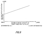
- the front three-way catalyst 8 has a lower oxygen storage capacity than the rear three-way catalyst 9, and the width of air-fuel ratio fluctuation suited to the front three-way catalyst 8 is smaller than the width of air-fuel ratio fluctuation suited to the rear three-way catalyst 9. Therefore, PLb , PRb are set to much larger values than PLa , PRa , which can supply an amount of HC, CO, NOx and O 2 to the rear three-way catalyst 9 that can quickly raise its temperature.
- the air-fuel ratio fluctuation width suitable for the front three-way catalyst 8 is an air-fuel ratio fluctuation width suitable for the rear three-way catalyst 9
- the air-fuel ratio fluctuation is weakened in the front three-way catalyst 8 and the exhaust pipe 7 beyond it
- Fig. 8 is a routine for setting PLb and PRb according to the degree of the deterioration of the front three-way catalyst 8.
- step S411 it is determined whether or not detection of the deterioration of the front three-way catalyst 8 was performed.
- the deterioration of the front three-way catalyst 8 is detected under the following conditions, for example:
- the F/B conditions are satisfied when the following three conditions are all satisfied.
- HZRATE the degree of deterioration of the front three-way catalyst 8 will be larger the larger is HZRATE .
- a new HZRATE it is determined that "deterioration detection was performed", and a step S412 is performed. As long as there is no calculation of a new HZRATE , the setting on the immediately preceding occasion is maintained.
- PLb and PRb are computed by substituting HZRATE in functions f8 and f9 .
- the functions f8 and f9 are therefore defined so that the magnitudes of PLb and PRb are smaller the larger the degree of deterioration HZRATE of the front three-way catalyst 8.
- PLb , PRb are set to values ( f8 (0), f9 (0)) corresponding to catalysts without deterioration until the first detection of catalyst deterioration is performed.
- Fig. 10 is a routine for setting PHOSR according to the SOx discharge amount.
- step S421 it is determined whether or not rich air-fuel ratio conditions are satisfied based on the flag Frich .
- PHOSR is computed by substituting the SOx storage amount SOX and catalyst temperature Tcat of the rear three-way catalyst 9 in the function f3 .
- the function f3 is defined so that the richness due to PHOSR has the following characteristics.
- PHOSR is set according to the SOx discharge amount.
- the SOx discharge amount varies as shown in Fig. 11 according to the time after starting rich air-fuel ratio control, and since the SOx storage amount decreases with the elapsed time, the richness decreases the longer the elapsed time after starting rich air-fuel ratio control.
- Fig. 12 is a routine for computing the air-fuel ratio feedback correction coefficient ⁇ . This routine is performed by the controller 6 at a predetermined interval, for example, 10 milliseconds.
- the correction coefficient ⁇ in air-fuel ratio feedback control is computed.
- the output of the front oxygen sensor 10 is A/D converted, and an oxygen concentration signal OSF1 is calculated.
- a step S502 it is determined whether or not F/B conditions are satisfied.
- routine proceeds to a step S503, otherwise the routine proceeds to a step S513.
- the air-fuel ratio feed back control correction coefficient ⁇ is computed by proportional control using the basic control constants (rich air-fuel ratio proportional gain PL1 , lean air-fuel ratio proportional gain PR1 ) and the correction value PHOS , and integral control using the basic control constants (rich air-fuel ratio integral gain IL , lean air-fuel ratio integral gain IR ) based on the comparison result of the oxygen concentration signal OSF1 and a threshold limit value SLF1 .
- the subscript z attached to the correction coefficient ⁇ in the flowchart denotes the value computed on the immediately preceding occasion (value computed 10 milliseconds ago).
- the correction coefficient ⁇ is set to 1.
- the correction coefficient ⁇ computed by this routine is used in a routine for computing the fuel injection timing and fuel injection amount, described later.
- Fig. 13 is a routine for setting a target air-fuel ratio. This routine is performed by the controller 6 at a predetermined interval, for example 10 milliseconds.
- the target air-fuel ratio (target equivalence ratio) is set according to running conditions and whether rich air-fuel ratio conditions are satisfied.
- the engine rotation speed N is calculated based on the recurrence interval of a predetermined signal of the crank angle sensor 14.
- the engine load T is also calculated based on the output of the accelerator position sensor 15.
- the target equivalence ratio TFBYA is set according to the engine rotation speed N and engine load T by referring to a target equivalence ratio setting map shown in Fig. 4.
- the target equivalence ratio TFBYA is the ratio of the stoichiometric air-fuel ratio and target air-fuel ratio (stoichiometric air-fuel ratio/target air-fuel ratio).
- TFBYA is 1, the air fuel ratio is the stoichiometric air fuel ratio, when it is greater than 1, the air fuel ratio is rich, and when it is less than 1, the air fuel ratio is lean.
- step S603 it is determined whether or not rich air-fuel ratio conditions are satisfied based on the flag Frich .
- Frich 1
- step S604 it is determined whether or not TFBYA which was set in the step S602, is smaller than 1.
- TFBYA is smaller than 1
- the routine proceeds to a step S605, and in the step S605, TFBYA is set to 1.
- the target equivalence ratio TFBYA is set according to running conditions, but if rich air-fuel ratio conditions are satisfied, the target equivalence ratio TFBYA is set to 1 even if running conditions are in the lean air-fuel ratio operating region.
- the target equivalence ratio TFBYA set here is used to compute fuel injection amount in a fuel injection timing and fuel injection amount setting routine described later, and also in various other routines as a value representing the air-fuel ratio.
- Fig. 14 is a routine for setting the fuel injection timing and fuel injection amount. This routine is performed at a predetermined interval, for example 10 milliseconds.
- a fuel injection amount Ti and fuel injection timing TITM are computed so that the target equivalence ratio TFBYA set in the above routine for setting the target air-fuel ratio, is realized.
- an intake air amount Qa is calculated based on the output of the air flow meter 3.
- the engine rotation speed N is calculated based on the recurrence interval of a predetermined signal of the crank angle sensor 14.
- a basic fuel injection amount Tp i.e., an amount equivalence to the stoichiometric air-fuel ratio
- Tp K ⁇ Qa / N based on the intake air amount Qa and engine rotation speed N .
- K is a predetermined coefficient.
- the basic fuel injection amount Tp is corrected by the target equivalence ratio TFBYA , fuel increase amount correction coefficient COEF and air-fuel ratio feedback correction coefficient ⁇ .
- the fuel increase amount correction coefficient COEF collectively represents a fuel increase amount correction coefficient after startup and a water temperature increase amount correction coefficient.
- COEF is larger than 1
- COEF is 1.
- a fuel injection timing TITM is computed based on the fuel injection amount Ti computed in the step S703, and the engine rotation speed N .
- the computed fuel injection amount Ti and fuel injection timing TITM are recorded by the memory in the controller 6, and read and used by a fuel injection routine, not shown, which is performed in synchronism with the rotation of the engine 1.
- a signal is for example output to the injector 5 so that a fuel amount obtained by adding an ineffectual injection amount Ts to the fuel injection amount Ti is injected at a crank angle determined by the fuel injection timing TITM .
- stratified charge combustion is performed when running at a lean air-fuel ratio, and uniform charge combustion is performed when running at the stoichiometric air-fuel ratio or a rich air-fuel ratio. For this reason, when running at a lean air-fuel ratio, the fuel injection timing TITM is set in the compression stroke. When running at the stoichiometric air-fuel ratio or a rich air-fuel ratio, the fuel injection timing TITM is set in the intake stroke.
- Fig. 15 is a routine for setting an ignition timing ADV . This routine is performed by the controller 6 at a predetermined interval, for example 10 milliseconds.
- the ignition timing ADV is set based on the flag Fheat which is set by the routine for determining the above-mentioned temperature increase conditions.
- a step S801 it is determined whether or not the temperature increase conditions in the rear three-way catalyst 9 are satisfied based on the flag Fheat .
- the ignition timing ADV is computed by deducting a predetermined retardation correction value RTD from an ignition timing ADVC set previously according to running conditions (engine rotation speed N , engine load T ).
- the ignition timing ADVC is set to, for example, a timing at which the output of the engine is greatest in a region where knocking does not occur. If the ignition timing is retarded from ADVC , combustion will be retarded and the exhaust gas temperature will rise. The relation of retardation angle amount and exhaust gas temperature is shown in Fig. 16. The exhaust gas temperature rises the larger the retardation angle.
- step S803 the ignition timing ADV is set to ADVC .
- this routine it is determined whether or not the conditions for increasing the temperature of the rear three-way catalyst 9 are satisfied based on the flag Fheat from the temperature increase condition determining routine.
- the ignition timing ADV is retarded by the predetermined amount RTD in order to increase the temperature.
- An ignition signal is then output to an ignition plug 19 in an ignition control routine, not shown, based on this ignition timing ADV .
- Fig. 17 is a routine for setting an exhaust valve open timing EVO . This routine is performed by the controller 6 at a predetermined interval, for example 10 milliseconds.
- the open timing EVO of the exhaust valve is set based on the flag Fheat set by the routine for determining the temperature increase conditions.
- a step S901 it is determined whether or not temperature increase conditions of the rear three-way catalyst 9 are satisfied based on the flag Fheat .
- an exhaust valve open timing EVO is set to a more advanced position than for normal running. If the exhaust valve open timing EVO is advanced, gas at the end of the expansion stroke will flow into the exhaust pipe 7, so the exhaust gas temperature rises.
- the relation of the exhaust valve open timing EVO and exhaust gas temperature is shown in Fig. 18.
- the exhaust gas temperature rises the larger the advance angle of the exhaust valve open timing EVO .
- a drive signal is then output to a variable valve mechanism of the engine 1 by a valve control routine, not shown, so that the exhaust valve open timing is the exhaust valve open timing EVO .
- the controller 6 determines whether the conditions are satisfied for discharging SOx stored in the rear three-way catalyst 9, and when SOx discharge conditions are satisfied, SOx discharge control of the rear three-way catalyst 9 is performed.
- the amplitude of the air-fuel ratio fluctuation of the exhaust gas flowing into the front three-way catalyst 8 is increased by increasing the gain of air-fuel ratio feedback control, and the amount of CO, HC, NOx and O 2 passing through the front three-way catalyst 8 and flowing into the rear three-way catalyst 9 is increased.
- the temperature of the rear three-way catalyst 9 rises due to the heat of reaction when these gases react on the rear three-way catalyst 9, and the stored SOx is discharged.
- the degree of deterioration of the front three-way catalyst 8 becomes large, the amount of HC, CO, NOx and O 2 passing through the front three-way catalyst 8 and flowing into the rear three-way catalyst 9 will increase, even for the same air-fuel ratio fluctuation.
- the amplitude of the air-fuel ratio fluctuation is adjusted according to the degree of deterioration of the front three-way catalyst 8, so the temperature rise characteristics of the rear three-way catalyst 9 are maintained at about the same level.
- the median of the air-fuel ratio of the exhaust gas flowing into the rear three-way catalyst 9 is feedback controlled to the stoichiometric air-fuel ratio.
- the ignition timing of the engine 1 is retarded and the open timing of the exhaust valve is advanced to increase the exhaust gas temperature.
- the basic control constants PL1 and PR1 are set to PLb , and PRb , and the amplitude of the air-fuel ratio fluctuation under air-fuel ratio feedback control increases.
- the purification rate of the front three-way catalyst 8 decreases, and the amount of HC, CO, NOx and O 2 passing through the front three-way catalyst 8 and flowing into the rear three-way catalyst 9, increases. Further, the reaction efficiency on the rear three-way catalyst 9 is maximized by controlling the air-fuel ratio to the stoichiometric air-fuel ratio in this way, and the temperature rise effect of the rear three-way catalyst 9 is enhanced.
- the correction value PHOS is set to PHOSR , and the average air-fuel ratio of the exhaust gas flowing into the front three-way catalyst 8 and the rear three-way catalyst 9 is controlled to rich.
- SOx discharge from the rear three-way catalyst 9 is promoted, and the discharged SOx is reduced by unburnt fuel.
- the basic control constants PL1 and PR1 are set to PLa and PRa to prevent deterioration of the rear three-way catalyst 9, the amplitude of the air-fuel ratio fluctuation under air-fuel ratio feedback control returns to the usual magnitude, and the catalyst temperature of the rear three-way catalyst 9 is prevented from rising excessively.
- the ignition timing and exhaust valve open timing also return to their usual timings, and temperature rise of the rear three-way catalyst 9 is suppressed. It may be noted that, as the correction value PHOS is set to PHOSR , the exhaust gas flowing into the front three-way catalyst 8 and the rear three-way catalyst 9 is still rich.
- the average air-fuel ratio of the exhaust gas flowing into the front three-way catalyst 8 and the rear three-way catalyst 9 is controlled to rich, and discharged SOx is reduced.
- the second embodiment differs from the first embodiment in the routine for determining SOx discharge conditions.
- SOx discharge conditions are determined based on the output of an NOx sensor 18 provided behind the rear three-way catalyst 9.
- Fig. 20 shows a routine for determining SOx discharge conditions. This routine is performed by the controller 6 at a predetermined interval, for example 10 milliseconds.
- a step S151 the output of the NOx sensor 18 is A/D converted, and an NOx concentration signal NOXS is calculated.
- the output of the catalyst temperature sensor 12 is also A/D converted, and the catalyst temperature Tcat of the rear three-way catalyst 9 is calculated.
- the engine rotation speed N is also calculated based on the recurrence interval of a predetermined signal of the crank angle sensor 14, and the engine load T is calculated based on the output of the accelerator position sensor 15.
- a step S152 it is determined whether or not the air-fuel ratio is controlled to be lean based on the target equivalence ratio TFBYA .
- TFBYA target equivalence ratio
- the routine proceeds to a step S153 , and when it is not, the routine proceeds to a step S160 .
- ⁇ NOX (NOx amount which flows into the rear three-way catalyst 9 in a predetermined time)
- ⁇ NOx trapping rate of rear three-way catalyst 9
- the NOx amount flowing into the rear three-way catalyst 9 in the predetermined time is computed based on the rotation speed N of the engine 1, engine load T and average air-fuel ratio.
- the NOx trapping rate (NOx amount trapped in unit time / NOx amount flowing in per unit time) of the rear three-way catalyst 9 is computed based on, for example, the present NOx storage amount (estimated value of NOx storage amount computed on the immediately preceding occasion) NOX z, catalyst temperature Tcat and average air-fuel ratio.
- the target equivalence ratio TFBYA set in the target air-fuel ratio setting routine is used.
- the NOx trapping rate of the rear three-way catalyst 9 is a value from zero to 1, and has the following characteristics.
- a step S154 the newest estimated NOx amount NOX is computed by adding ⁇ NOX to the estimated NOx amount NOXz computed on the immediately preceding occasion.
- a step S155 it is determined whether or not the estimated NOx amount NOX is greater than a predetermined amount NOXth .
- the routine proceeds to a step S156, and in other cases the routine is terminated.
- the predetermined amount NOXth is set to the NOx storage tolerance of the rear three-way catalyst 9 or a slightly smaller value.
- a flag Fnox is set to 1 which shows that the conditions for reducing the NOx stored in the rear three-way catalyst 9 are satisfied.
- control is performed by a routine, not shown, which temporarily makes the air-fuel ratio rich.
- a step S157 it is determined whether or not an NOx concentration signal NOXS is greater than a permitted value NOXSth .
- the NOx trapping rate of the rear three-way catalyst 9 falls off the more the total amount of NOx and SOx stored in the rear three-way catalyst 9 increases, so if the total amount of NOx and SOx increases, the NOx concentration downstream of the rear three-way catalyst 9 will increase as shown in Fig. 21.
- a counter Trich for measuring the elapsed time after rich air-fuel ratio conditions are satisfied is reset to zero.
- a step S159 the flag Fsox which shows that SOx discharge conditions are satisfied, is set to 1.
- the estimated NOx storage amount NOX is set to zero. This is because, if the air-fuel ratio is controlled to the stoichiometric air-fuel ratio or to rich, the NOx stored in the rear three-way catalyst 9 is rapidly reduced.
- the flag Fnox is set to zero.
- step S162 it is determined whether or not rich air-fuel ratio conditions are satisfied.
- a step S164 it is determined whether or not the elapsed time Trich after rich air-fuel ratio conditions are satisfied, exceeded a predetermined time Trth .
- Trth it is determined that SOx stored in the rear three-way catalyst 9 has been discharged by setting the air-fuel ratio to rich for a predetermined time.
- the routine then proceeds to a step S165, and the flag Fsox is set to zero which shows that SOx discharge conditions are not satisfied.
- the step S153 may be omitted, and ⁇ NOX of the step S154 may be set to a fixed value.
- the NOx amount stored in the rear three-way catalyst 9 exceeds a predetermined amount and the NOx concentration of the rear three-way catalyst 9 downstream of the rear three-way catalyst 9 exceeds a predetermined value, it is determined that SOx discharge conditions are satisfied.
- the predetermined time Trth has elapsed after rich air-fuel ratio conditions are satisfied, it is determined that SOx discharge conditions are not satisfied.
- Fig. 22 is a routine for setting PHOSR to be variable in the second embodiment.
- step S251 it is determined whether or not rich air-fuel ratio conditions are satisfied based on the flag Frich .
- Frich 1
- step S252 it is determined whether or not rich air-fuel ratio conditions are satisfied.
- PHOSR is computed by a function f7 .
- the function f7 is determined so that the richness decided by PHOSR has the following characteristics.
- the routine for determining SOx discharge conditions according to the third embodiment differs from that of the first embodiment.
- Fig. 23 shows the routine for determining SOx discharge conditions. This routine is performed at a predetermined interval, for example, 10 milliseconds, by the controller 6.
- step S171 it is determined whether the timing is immediately after engine startup based on the variation of the output signal from the starter switch 17.
- the routine proceeds to a step S171, otherwise it proceeds to a step S174.
- a step S172 the variable Trich is set to zero.
- the flag Fsox is set to 1.
- a step S174 it is determined whether the rich air-fuel ratio conditions are satisfied based on the flag Frich .
- step S175 Trich is counted.
- step S176 it is determined whether Trich exceeded the predetermined value Trth .
- the routine proceeds to a step S177, and the flag Fsox is set to zero which shows that SOx discharge conditions are not satisfied. In other cases, the routine is terminated.
Landscapes
- Engineering & Computer Science (AREA)
- Chemical & Material Sciences (AREA)
- Combustion & Propulsion (AREA)
- Mechanical Engineering (AREA)
- General Engineering & Computer Science (AREA)
- Exhaust Gas After Treatment (AREA)
- Electrical Control Of Air Or Fuel Supplied To Internal-Combustion Engine (AREA)
- Electrical Control Of Ignition Timing (AREA)
- Output Control And Ontrol Of Special Type Engine (AREA)
- Combined Controls Of Internal Combustion Engines (AREA)
Applications Claiming Priority (2)
| Application Number | Priority Date | Filing Date | Title |
|---|---|---|---|
| JP07231999A JP4158268B2 (ja) | 1999-03-17 | 1999-03-17 | エンジンの排気浄化装置 |
| JP7231999 | 1999-03-17 |
Publications (3)
| Publication Number | Publication Date |
|---|---|
| EP1036927A2 true EP1036927A2 (de) | 2000-09-20 |
| EP1036927A3 EP1036927A3 (de) | 2003-06-18 |
| EP1036927B1 EP1036927B1 (de) | 2005-09-28 |
Family
ID=13485853
Family Applications (1)
| Application Number | Title | Priority Date | Filing Date |
|---|---|---|---|
| EP00105574A Expired - Lifetime EP1036927B1 (de) | 1999-03-17 | 2000-03-16 | Abgasentgiftungsanlage einer Brennkraftmaschine |
Country Status (4)
| Country | Link |
|---|---|
| US (1) | US6679050B1 (de) |
| EP (1) | EP1036927B1 (de) |
| JP (1) | JP4158268B2 (de) |
| DE (1) | DE60022806T2 (de) |
Cited By (6)
| Publication number | Priority date | Publication date | Assignee | Title |
|---|---|---|---|---|
| EP1365130A1 (de) * | 2002-05-16 | 2003-11-26 | Nissan Motor Co., Ltd. | Vorrichtung und Verfahren zur Abgasreinigung einer Brennkraftmaschine |
| DE10320890B4 (de) * | 2003-05-09 | 2013-01-31 | Robert Bosch Gmbh | Aufheizen von Katalysatoren beim Betrieb von Verbrennungsmotoren mit Direkteinspritzung |
| DE10320891B4 (de) * | 2003-05-09 | 2013-02-07 | Robert Bosch Gmbh | Katalysatorheizverfahren und Steuergerät zur Steuerung von Katalysatorheizverfahren |
| DE10321311B4 (de) * | 2003-05-08 | 2013-09-12 | Volkswagen Ag | Verfahren zum Aufheizen eines Katalysators und Kraftmaschine mit Steuereinheit |
| EP2366879A3 (de) * | 2010-03-17 | 2014-09-10 | Hitachi Automotive Systems, Ltd. | Steuerungsverfahren für eine Brennkraftmaschine |
| DE112008000369B4 (de) * | 2007-02-21 | 2014-09-11 | Toyota Jidosha Kabushiki Kaisha | Abgasreinigungsvorrichtung für Verbrennungsmotor |
Families Citing this family (54)
| Publication number | Priority date | Publication date | Assignee | Title |
|---|---|---|---|---|
| US6901749B2 (en) * | 2000-08-01 | 2005-06-07 | Honda Giken Kogyo Kabushiki Kaisha | Exhaust emission control system for internal combustion engine |
| JP3659193B2 (ja) | 2001-06-08 | 2005-06-15 | 日産自動車株式会社 | 内燃機関の排気浄化システム |
| US7198952B2 (en) * | 2001-07-18 | 2007-04-03 | Toyota Jidosha Kabushiki Kaisha | Catalyst deterioration detecting apparatus and method |
| EP1475521B1 (de) * | 2002-02-12 | 2019-03-27 | Isuzu Motors Limited | Abgasdekontaminierungssystem und abgasdekontaminierungsverfahren |
| JP3791470B2 (ja) * | 2002-07-02 | 2006-06-28 | トヨタ自動車株式会社 | 内燃機関の排気浄化装置 |
| JP2004068700A (ja) * | 2002-08-06 | 2004-03-04 | Toyota Motor Corp | 排気ガス浄化方法 |
| DE10246505A1 (de) * | 2002-10-05 | 2004-04-15 | Robert Bosch Gmbh | Verfahren zum Betreiben einer Brennkraftmaschine sowie die Brennkraftmaschine selbst |
| US7043901B2 (en) * | 2003-03-20 | 2006-05-16 | Ford Global Technologies, Llc | Device and method for internal combustion engine control |
| FR2866925B1 (fr) * | 2004-02-27 | 2006-10-13 | Peugeot Citroen Automobiles Sa | Procede de controle du traitement des gaz d'echappement d'un moteur thermique et vehicule a moteur thermique mettant en oeuvre ce procede |
| FR2866926B1 (fr) * | 2004-02-27 | 2008-02-22 | Peugeot Citroen Automobiles Sa | Procede de diagnostic pour un catalyseur de gaz d'echappement d'un moteur thermique et vehicule mettant en oeuvre ce procede |
| US7743606B2 (en) * | 2004-11-18 | 2010-06-29 | Honeywell International Inc. | Exhaust catalyst system |
| US7182075B2 (en) * | 2004-12-07 | 2007-02-27 | Honeywell International Inc. | EGR system |
| US7461504B2 (en) * | 2004-12-21 | 2008-12-09 | Detroit Diesel Corporation | Method and system for controlling temperatures of exhaust gases emitted from internal combustion engine to facilitate regeneration of a particulate filter |
| US7591135B2 (en) * | 2004-12-29 | 2009-09-22 | Honeywell International Inc. | Method and system for using a measure of fueling rate in the air side control of an engine |
| US7467614B2 (en) | 2004-12-29 | 2008-12-23 | Honeywell International Inc. | Pedal position and/or pedal change rate for use in control of an engine |
| US7165399B2 (en) * | 2004-12-29 | 2007-01-23 | Honeywell International Inc. | Method and system for using a measure of fueling rate in the air side control of an engine |
| US7275374B2 (en) * | 2004-12-29 | 2007-10-02 | Honeywell International Inc. | Coordinated multivariable control of fuel and air in engines |
| US7328577B2 (en) | 2004-12-29 | 2008-02-12 | Honeywell International Inc. | Multivariable control for an engine |
| US20060168945A1 (en) * | 2005-02-02 | 2006-08-03 | Honeywell International Inc. | Aftertreatment for combustion engines |
| US7752840B2 (en) * | 2005-03-24 | 2010-07-13 | Honeywell International Inc. | Engine exhaust heat exchanger |
| JP4100412B2 (ja) * | 2005-04-12 | 2008-06-11 | トヨタ自動車株式会社 | 圧縮着火式内燃機関の排気浄化装置 |
| US7469177B2 (en) * | 2005-06-17 | 2008-12-23 | Honeywell International Inc. | Distributed control architecture for powertrains |
| US7389773B2 (en) | 2005-08-18 | 2008-06-24 | Honeywell International Inc. | Emissions sensors for fuel control in engines |
| US7155334B1 (en) | 2005-09-29 | 2006-12-26 | Honeywell International Inc. | Use of sensors in a state observer for a diesel engine |
| US7765792B2 (en) * | 2005-10-21 | 2010-08-03 | Honeywell International Inc. | System for particulate matter sensor signal processing |
| US7357125B2 (en) * | 2005-10-26 | 2008-04-15 | Honeywell International Inc. | Exhaust gas recirculation system |
| JP4270201B2 (ja) * | 2005-12-05 | 2009-05-27 | トヨタ自動車株式会社 | 内燃機関 |
| US20070144149A1 (en) * | 2005-12-28 | 2007-06-28 | Honeywell International Inc. | Controlled regeneration system |
| US7415389B2 (en) * | 2005-12-29 | 2008-08-19 | Honeywell International Inc. | Calibration of engine control systems |
| DE102006014249A1 (de) * | 2006-03-28 | 2007-10-04 | Robert Bosch Gmbh | Verfahren zur Vorsteuerung eines Lambda-Wertes |
| JP4487971B2 (ja) | 2006-04-24 | 2010-06-23 | トヨタ自動車株式会社 | 内燃機関の空燃比制御装置 |
| JP4436397B2 (ja) * | 2007-10-01 | 2010-03-24 | 本田技研工業株式会社 | 内燃機関の排ガス浄化装置 |
| US8060290B2 (en) | 2008-07-17 | 2011-11-15 | Honeywell International Inc. | Configurable automotive controller |
| US8620461B2 (en) | 2009-09-24 | 2013-12-31 | Honeywell International, Inc. | Method and system for updating tuning parameters of a controller |
| US8621852B2 (en) * | 2009-11-26 | 2014-01-07 | Toyota Jidosha Kabushiki Kaisha | Detector for detecting sulfur components |
| US8504175B2 (en) | 2010-06-02 | 2013-08-06 | Honeywell International Inc. | Using model predictive control to optimize variable trajectories and system control |
| US9677493B2 (en) | 2011-09-19 | 2017-06-13 | Honeywell Spol, S.R.O. | Coordinated engine and emissions control system |
| US20130111905A1 (en) | 2011-11-04 | 2013-05-09 | Honeywell Spol. S.R.O. | Integrated optimization and control of an engine and aftertreatment system |
| US9650934B2 (en) | 2011-11-04 | 2017-05-16 | Honeywell spol.s.r.o. | Engine and aftertreatment optimization system |
| JP5811185B2 (ja) * | 2011-11-17 | 2015-11-11 | トヨタ自動車株式会社 | 内燃機関の制御装置 |
| JP5738249B2 (ja) | 2012-09-13 | 2015-06-17 | 本田技研工業株式会社 | 内燃機関の排気浄化システム |
| EP3051367B1 (de) | 2015-01-28 | 2020-11-25 | Honeywell spol s.r.o. | Ansatz und system zur handhabung von einschränkungen für gemessene störungen mit unsicherer vorschau |
| EP3056706A1 (de) | 2015-02-16 | 2016-08-17 | Honeywell International Inc. | Ansatz zur nachbehandlungssystemmodellierung und modellidentifizierung |
| EP3091212A1 (de) | 2015-05-06 | 2016-11-09 | Honeywell International Inc. | Identifikationsansatz für verbrennungsmotor-mittelwertmodelle |
| EP3125052B1 (de) | 2015-07-31 | 2020-09-02 | Garrett Transportation I Inc. | Quadratischer programmlöser für mpc mit variabler anordnung |
| US10272779B2 (en) | 2015-08-05 | 2019-04-30 | Garrett Transportation I Inc. | System and approach for dynamic vehicle speed optimization |
| US10415492B2 (en) | 2016-01-29 | 2019-09-17 | Garrett Transportation I Inc. | Engine system with inferential sensor |
| US10124750B2 (en) | 2016-04-26 | 2018-11-13 | Honeywell International Inc. | Vehicle security module system |
| US10036338B2 (en) | 2016-04-26 | 2018-07-31 | Honeywell International Inc. | Condition-based powertrain control system |
| EP3548729B1 (de) | 2016-11-29 | 2023-02-22 | Garrett Transportation I Inc. | Inferenzflusssensor |
| US11057213B2 (en) | 2017-10-13 | 2021-07-06 | Garrett Transportation I, Inc. | Authentication system for electronic control unit on a bus |
| JP7283043B2 (ja) | 2018-09-18 | 2023-05-30 | 三菱自動車工業株式会社 | 内燃機関の排気制御装置 |
| CN114673599B (zh) * | 2022-04-18 | 2023-04-28 | 中国第一汽车股份有限公司 | 颗粒捕集器驻车再生的控制方法、控制装置及处理器 |
| CN117759412B (zh) * | 2024-02-22 | 2024-05-17 | 潍柴动力股份有限公司 | 一种三元催化器控制方法、装置、存储介质及电子设备 |
Citations (2)
| Publication number | Priority date | Publication date | Assignee | Title |
|---|---|---|---|---|
| JPH06336916A (ja) | 1993-05-31 | 1994-12-06 | Toyota Motor Corp | 内燃機関の排気浄化装置 |
| JPH1054274A (ja) | 1996-08-12 | 1998-02-24 | Toyota Motor Corp | 内燃機関の排気浄化装置 |
Family Cites Families (12)
| Publication number | Priority date | Publication date | Assignee | Title |
|---|---|---|---|---|
| KR100288406B1 (ko) * | 1992-12-14 | 2001-06-01 | 밀러 제임스 이 | 엔진의 공연비 제어장치 |
| JP3577728B2 (ja) * | 1993-12-03 | 2004-10-13 | 株式会社デンソー | 内燃機関の空燃比制御装置 |
| DE69730539T2 (de) * | 1996-06-10 | 2005-06-23 | Hitachi, Ltd. | Abgasreinigungsanlage einer Brennkraftmaschine und Katalysator zum Reinigen des Abgases einer Brennkraftmaschine |
| GB2324052A (en) | 1997-04-11 | 1998-10-14 | Ford Motor Co | Heating of a storage trap |
| JP3237607B2 (ja) * | 1997-05-26 | 2001-12-10 | トヨタ自動車株式会社 | 内燃機関の触媒被毒再生装置 |
| DE59807160D1 (de) * | 1997-07-19 | 2003-03-20 | Volkswagen Ag | Verfahren und Vorrichtung zur Überwachung der De-Sulfatierung bei NOx-Speicherkatalysatoren |
| US5974788A (en) | 1997-08-29 | 1999-11-02 | Ford Global Technologies, Inc. | Method and apparatus for desulfating a nox trap |
| DE19802631C1 (de) * | 1998-01-24 | 1999-07-22 | Daimler Chrysler Ag | Verfahren und Einrichtung zum Reinigen von Abgasen eines Verbrennungsmotors |
| US6205776B1 (en) * | 1998-02-24 | 2001-03-27 | Toyota Jidosha Kabushiki Kaisha | Air-fuel ration control system for multi-cylinder internal combustion engine |
| JP3360645B2 (ja) | 1998-04-15 | 2002-12-24 | 日産自動車株式会社 | 内燃機関の排気浄化装置 |
| US6237330B1 (en) | 1998-04-15 | 2001-05-29 | Nissan Motor Co., Ltd. | Exhaust purification device for internal combustion engine |
| US6205773B1 (en) * | 1998-07-07 | 2001-03-27 | Toyota Jidosha Kabushiki Kaisha | Exhaust gas purification device for an internal combustion engine |
-
1999
- 1999-03-17 JP JP07231999A patent/JP4158268B2/ja not_active Expired - Fee Related
-
2000
- 2000-03-16 EP EP00105574A patent/EP1036927B1/de not_active Expired - Lifetime
- 2000-03-16 US US09/527,519 patent/US6679050B1/en not_active Expired - Fee Related
- 2000-03-16 DE DE60022806T patent/DE60022806T2/de not_active Expired - Lifetime
Patent Citations (2)
| Publication number | Priority date | Publication date | Assignee | Title |
|---|---|---|---|---|
| JPH06336916A (ja) | 1993-05-31 | 1994-12-06 | Toyota Motor Corp | 内燃機関の排気浄化装置 |
| JPH1054274A (ja) | 1996-08-12 | 1998-02-24 | Toyota Motor Corp | 内燃機関の排気浄化装置 |
Cited By (7)
| Publication number | Priority date | Publication date | Assignee | Title |
|---|---|---|---|---|
| EP1365130A1 (de) * | 2002-05-16 | 2003-11-26 | Nissan Motor Co., Ltd. | Vorrichtung und Verfahren zur Abgasreinigung einer Brennkraftmaschine |
| US7036304B2 (en) | 2002-05-16 | 2006-05-02 | Nissan Motor Co., Ltd. | Exhaust gas purifying apparatus and method for internal combustion engine |
| DE10321311B4 (de) * | 2003-05-08 | 2013-09-12 | Volkswagen Ag | Verfahren zum Aufheizen eines Katalysators und Kraftmaschine mit Steuereinheit |
| DE10320890B4 (de) * | 2003-05-09 | 2013-01-31 | Robert Bosch Gmbh | Aufheizen von Katalysatoren beim Betrieb von Verbrennungsmotoren mit Direkteinspritzung |
| DE10320891B4 (de) * | 2003-05-09 | 2013-02-07 | Robert Bosch Gmbh | Katalysatorheizverfahren und Steuergerät zur Steuerung von Katalysatorheizverfahren |
| DE112008000369B4 (de) * | 2007-02-21 | 2014-09-11 | Toyota Jidosha Kabushiki Kaisha | Abgasreinigungsvorrichtung für Verbrennungsmotor |
| EP2366879A3 (de) * | 2010-03-17 | 2014-09-10 | Hitachi Automotive Systems, Ltd. | Steuerungsverfahren für eine Brennkraftmaschine |
Also Published As
| Publication number | Publication date |
|---|---|
| EP1036927B1 (de) | 2005-09-28 |
| DE60022806D1 (de) | 2005-11-03 |
| EP1036927A3 (de) | 2003-06-18 |
| US6679050B1 (en) | 2004-01-20 |
| DE60022806T2 (de) | 2006-03-23 |
| JP2000265885A (ja) | 2000-09-26 |
| JP4158268B2 (ja) | 2008-10-01 |
Similar Documents
| Publication | Publication Date | Title |
|---|---|---|
| EP1036927B1 (de) | Abgasentgiftungsanlage einer Brennkraftmaschine | |
| US6233923B1 (en) | Exhaust emission control device of internal combustion engine | |
| US6263666B1 (en) | Exhaust emission control device for internal combustion engine | |
| KR0150432B1 (ko) | 내연엔진의 제어장치 및 제어방법 | |
| EP1277942A2 (de) | Verfahren und Vorrichtung zur Steuerung einer Brennkraftmaschine mit Direkteinspritzung | |
| JP2003206732A (ja) | 排気浄化装置付き内燃機関 | |
| JP3493698B2 (ja) | 内燃機関の点火時期制御装置 | |
| US6550449B2 (en) | Control system for internal combustion engine | |
| EP1229235B1 (de) | Steuervorrichtung für eine Brennkraftmaschine mit Direkteinspritzung | |
| US6327849B1 (en) | Exhaust gas purifying apparatus for internal combustion engine and controller for internal combustion engine | |
| US6467256B2 (en) | Exhaust emission control system for internal combustion engine | |
| EP1365130A1 (de) | Vorrichtung und Verfahren zur Abgasreinigung einer Brennkraftmaschine | |
| JP4062729B2 (ja) | 触媒早期暖機システムの異常診断装置 | |
| JP2019183733A (ja) | 空燃比制御装置 | |
| JP2004169711A (ja) | 内燃機関の触媒昇温制御装置 | |
| JP3937487B2 (ja) | 内燃機関の排気浄化装置 | |
| JP2000337130A (ja) | 内燃機関の排出ガス浄化装置 | |
| JP2001152835A (ja) | エンジンの排気浄化装置 | |
| JP2000130221A (ja) | 内燃機関の燃料噴射制御装置 | |
| JP3123438B2 (ja) | 内燃機関の排気浄化装置 | |
| JP4240943B2 (ja) | 内燃機関の定常運転状態判定装置 | |
| JP2000080914A (ja) | 内燃機関 | |
| JP3641016B2 (ja) | 内燃エンジンの空燃比フィードバック制御装置 | |
| JP2003097332A (ja) | 内燃機関の排気浄化装置および浄化法 | |
| JP3511670B2 (ja) | エンジンの制御装置 |
Legal Events
| Date | Code | Title | Description |
|---|---|---|---|
| PUAI | Public reference made under article 153(3) epc to a published international application that has entered the european phase |
Free format text: ORIGINAL CODE: 0009012 |
|
| 17P | Request for examination filed |
Effective date: 20000316 |
|
| AK | Designated contracting states |
Kind code of ref document: A2 Designated state(s): AT BE CH CY DE DK ES FI FR GB GR IE IT LI LU MC NL PT SE |
|
| AX | Request for extension of the european patent |
Free format text: AL;LT;LV;MK;RO;SI |
|
| PUAL | Search report despatched |
Free format text: ORIGINAL CODE: 0009013 |
|
| AK | Designated contracting states |
Designated state(s): AT BE CH CY DE DK ES FI FR GB GR IE IT LI LU MC NL PT SE |
|
| AX | Request for extension of the european patent |
Extension state: AL LT LV MK RO SI |
|
| 17Q | First examination report despatched |
Effective date: 20030807 |
|
| AKX | Designation fees paid |
Designated state(s): DE FR GB |
|
| GRAP | Despatch of communication of intention to grant a patent |
Free format text: ORIGINAL CODE: EPIDOSNIGR1 |
|
| GRAS | Grant fee paid |
Free format text: ORIGINAL CODE: EPIDOSNIGR3 |
|
| GRAA | (expected) grant |
Free format text: ORIGINAL CODE: 0009210 |
|
| AK | Designated contracting states |
Kind code of ref document: B1 Designated state(s): DE FR GB |
|
| REG | Reference to a national code |
Ref country code: GB Ref legal event code: FG4D |
|
| REF | Corresponds to: |
Ref document number: 60022806 Country of ref document: DE Date of ref document: 20051103 Kind code of ref document: P |
|
| ET | Fr: translation filed | ||
| PLBE | No opposition filed within time limit |
Free format text: ORIGINAL CODE: 0009261 |
|
| STAA | Information on the status of an ep patent application or granted ep patent |
Free format text: STATUS: NO OPPOSITION FILED WITHIN TIME LIMIT |
|
| 26N | No opposition filed |
Effective date: 20060629 |
|
| PGFP | Annual fee paid to national office [announced via postgrant information from national office to epo] |
Ref country code: FR Payment date: 20140311 Year of fee payment: 15 |
|
| PGFP | Annual fee paid to national office [announced via postgrant information from national office to epo] |
Ref country code: GB Payment date: 20140312 Year of fee payment: 15 |
|
| PGFP | Annual fee paid to national office [announced via postgrant information from national office to epo] |
Ref country code: DE Payment date: 20140417 Year of fee payment: 15 |
|
| REG | Reference to a national code |
Ref country code: DE Ref legal event code: R119 Ref document number: 60022806 Country of ref document: DE |
|
| GBPC | Gb: european patent ceased through non-payment of renewal fee |
Effective date: 20150316 |
|
| REG | Reference to a national code |
Ref country code: FR Ref legal event code: ST Effective date: 20151130 |
|
| PG25 | Lapsed in a contracting state [announced via postgrant information from national office to epo] |
Ref country code: DE Free format text: LAPSE BECAUSE OF NON-PAYMENT OF DUE FEES Effective date: 20151001 Ref country code: GB Free format text: LAPSE BECAUSE OF NON-PAYMENT OF DUE FEES Effective date: 20150316 |
|
| PG25 | Lapsed in a contracting state [announced via postgrant information from national office to epo] |
Ref country code: FR Free format text: LAPSE BECAUSE OF NON-PAYMENT OF DUE FEES Effective date: 20150331 |