EP1036752B1 - Verfahren und Vorrichtung zum Vereinzeln flächiger Güter - Google Patents
Verfahren und Vorrichtung zum Vereinzeln flächiger Güter Download PDFInfo
- Publication number
- EP1036752B1 EP1036752B1 EP00105240A EP00105240A EP1036752B1 EP 1036752 B1 EP1036752 B1 EP 1036752B1 EP 00105240 A EP00105240 A EP 00105240A EP 00105240 A EP00105240 A EP 00105240A EP 1036752 B1 EP1036752 B1 EP 1036752B1
- Authority
- EP
- European Patent Office
- Prior art keywords
- transport
- goods
- stack
- devices
- overhead
- Prior art date
- Legal status (The legal status is an assumption and is not a legal conclusion. Google has not performed a legal analysis and makes no representation as to the accuracy of the status listed.)
- Expired - Lifetime
Links
- 238000000034 method Methods 0.000 title description 11
- 230000005291 magnetic effect Effects 0.000 claims description 9
- 230000008569 process Effects 0.000 description 6
- 238000000926 separation method Methods 0.000 description 6
- 239000003302 ferromagnetic material Substances 0.000 description 4
- 239000002184 metal Substances 0.000 description 4
- 230000000694 effects Effects 0.000 description 3
- 230000003993 interaction Effects 0.000 description 3
- 230000001105 regulatory effect Effects 0.000 description 3
- 230000001133 acceleration Effects 0.000 description 2
- 230000008901 benefit Effects 0.000 description 2
- 239000011111 cardboard Substances 0.000 description 2
- 239000000123 paper Substances 0.000 description 2
- 230000000750 progressive effect Effects 0.000 description 2
- 230000000284 resting effect Effects 0.000 description 2
- 230000004913 activation Effects 0.000 description 1
- 230000001070 adhesive effect Effects 0.000 description 1
- 230000033228 biological regulation Effects 0.000 description 1
- 238000010276 construction Methods 0.000 description 1
- 230000036461 convulsion Effects 0.000 description 1
- 230000001419 dependent effect Effects 0.000 description 1
- 238000006073 displacement reaction Methods 0.000 description 1
- 238000011143 downstream manufacturing Methods 0.000 description 1
- 238000007665 sagging Methods 0.000 description 1
- 238000006748 scratching Methods 0.000 description 1
- 230000002393 scratching effect Effects 0.000 description 1
- 238000009987 spinning Methods 0.000 description 1
- 230000007704 transition Effects 0.000 description 1
Images

Classifications
-
- B—PERFORMING OPERATIONS; TRANSPORTING
- B65—CONVEYING; PACKING; STORING; HANDLING THIN OR FILAMENTARY MATERIAL
- B65H—HANDLING THIN OR FILAMENTARY MATERIAL, e.g. SHEETS, WEBS, CABLES
- B65H5/00—Feeding articles separated from piles; Feeding articles to machines
- B65H5/22—Feeding articles separated from piles; Feeding articles to machines by air-blast or suction device
- B65H5/222—Feeding articles separated from piles; Feeding articles to machines by air-blast or suction device by suction devices
- B65H5/224—Feeding articles separated from piles; Feeding articles to machines by air-blast or suction device by suction devices by suction belts
-
- B—PERFORMING OPERATIONS; TRANSPORTING
- B65—CONVEYING; PACKING; STORING; HANDLING THIN OR FILAMENTARY MATERIAL
- B65H—HANDLING THIN OR FILAMENTARY MATERIAL, e.g. SHEETS, WEBS, CABLES
- B65H3/00—Separating articles from piles
- B65H3/08—Separating articles from piles using pneumatic force
- B65H3/0808—Suction grippers
- B65H3/0816—Suction grippers separating from the top of pile
- B65H3/0825—Suction grippers separating from the top of pile and acting on the rear part of the articles relatively to the final separating direction
-
- B—PERFORMING OPERATIONS; TRANSPORTING
- B65—CONVEYING; PACKING; STORING; HANDLING THIN OR FILAMENTARY MATERIAL
- B65H—HANDLING THIN OR FILAMENTARY MATERIAL, e.g. SHEETS, WEBS, CABLES
- B65H2220/00—Function indicators
- B65H2220/09—Function indicators indicating that several of an entity are present
-
- B—PERFORMING OPERATIONS; TRANSPORTING
- B65—CONVEYING; PACKING; STORING; HANDLING THIN OR FILAMENTARY MATERIAL
- B65H—HANDLING THIN OR FILAMENTARY MATERIAL, e.g. SHEETS, WEBS, CABLES
- B65H2406/00—Means using fluid
- B65H2406/30—Suction means
- B65H2406/31—Suction box; Suction chambers
- B65H2406/312—Suction box; Suction chambers incorporating means for transporting the handled material against suction force
- B65H2406/3124—Belts
-
- B—PERFORMING OPERATIONS; TRANSPORTING
- B65—CONVEYING; PACKING; STORING; HANDLING THIN OR FILAMENTARY MATERIAL
- B65H—HANDLING THIN OR FILAMENTARY MATERIAL, e.g. SHEETS, WEBS, CABLES
- B65H2406/00—Means using fluid
- B65H2406/30—Suction means
- B65H2406/32—Suction belts
- B65H2406/323—Overhead suction belt, i.e. holding material against gravity
Definitions
- the invention relates to a device for separating of flat, stacked goods which, preferably a processing device, by far supplied to each other and one behind the other become.
- From DE 23 28 007 B is a turning and separating device for the topmost sheet a stack out, the several gripping elements to the topmost arch in the leading edge area lift off the stack and in the transport direction to move.
- the invention is based on the object, a device for separating flat, stacked Specify goods with which a large number of goods each unit of time lifted from the stack of goods and a further processing process can.
- a device for Separation of flat, stacked goods suggested the features mentioned in claim 1 having.
- the flat goods especially sheet metal, cardboard or paper sheets, These are individually from the Guterstapel taken in succession and a further processing individually forwarded. After taking off of the top estate of the good pile becomes this in Transport direction transported away for further processing. It is provided that the transport direction towards the vertical axis of the Guterstapels is inclined by an angle ⁇ . Under “vertical axis" of the stack of goods is understood that axle, the orthogonal to the base of the stacked Good progress.
- the device is characterized characterized in that the transport device has at least two transport devices, seen in the direction of transport in succession and each above the Guterstapels and respectively arranged in overlapping position to the goods stack and wherein the transport devices are independent mutually operating drives and a controller or control for the drives, at which the transport speeds of the transport devices independently adjustable or are controllable.
- the device comprises Accordingly, a decrease device and a Transport device for lifting the top Guts from the stack of goods and to transport the isolated Serve better.
- the goods are preferably fed to a further processing device.
- processing device also a freight transport facility or Separiervoroplasty or the like for the Goods understood.
- a first transport device is at rest, that is, at a standstill, located when the uppermost part of the Guterstapel partially removed while the second transport device, the first seen in the transport direction Transport device is downstream, an already completely lifted off the pile in the direction of transported the further processing device.
- a control or regulation for the drives is the transport speed of the transporting goods adjustable respectively adjustable.
- the transport devices as overhead suction belt sections are formed. These include at least each an endless band, also called Trum, which transits over Rollers, rollers or other guiding devices out where at least one of the rollers is drivable for rotation and preferably braked is.
- the endless belt is with a number of through holes provided and turned away on his the estate Side can be acted upon by a negative pressure, whereby a suction and holding the Guts the endless belt is possible.
- Adhesion (suction) serving negative pressure is preferably adjustable or switchable (on / off switching).
- the structure and function of an overhead suction belt conveyor is known, so here will not be discussed further.
- the overhead suction belt section several narrow, at a distance from each other and across Transport direction of the Guts arranged bands, in particular Endless belts, has, their respective Width is less than that of the estate.
- the transport devices designed as overhead magnetic stretches are made of ferromagnetic material existing goods can be used.
- Each of the overhead magnetic stretches includes at least an over rollers, rollers or other Leit Road Guided endless belt / Riementrum and at least a preferably switched on and off Electromagnet and / or at least one permanent magnet.
- the magnet can be opposite the drivable, preferably also braked strand on the side facing away from the goods to be transported be arranged stationary.
- Transport devices can each several - seen in the transport direction of the estate - in one Include spacing juxtaposed endless belts, each with at least one electromagnet or permanent magnets cooperate or are provided.
- the overhead magnetic stretches include These each have a linear motor whose structure and function is known per se.
- the acceptance device several acceptance devices having. These are transverse to the transport direction of the Guts, preferably next to each other and at a distance arranged distributed to each other, preferably in the trailing edge area of the stack lying on the Goods.
- a removal device of at least one lifting sucker educated This includes, for example, a Cylinder-piston unit, at the moving part (Piston rod or cylinder) with a negative pressure beaufschlagbarer suction head is attached, the by moving the moving part in the direction on the top, lying on the stack Good and is displaceable in the opposite direction.
- the suction head is designed such that the good sucked and held, so that by a displacement of the movable part of the cylinder-piston unit the goods lifted off the pile can be.
- the pickup device of at least one Solenoids formed, for separating from ferromagnetic material existing Gutern used is.
- the solenoid includes, for example a cylinder-piston unit, whose movable Part (piston rod or cylinder) at least one Permanent magnet and / or a switchable on and off Electromagnet is attached.
- the acceptance device both formed by Hubsaugern as well as lifting magnets Acceptance devices may include.
- an embodiment of the separating device preferred in which at least one of the transport devices at the same time Function of the acceptance device or one of the acceptance devices exercises.
- the transport device So it is designed so that they take off the top estate of the good pile and also its Transport takes place. It is additional or too alternatively possible that one of a take-off device initiated lifting of the highest asset from Good stack supported by the transport device becomes.
- an embodiment of the separating device which is characterized that the overhead holding functions of the in overlapping position to the goods stack Transport devices independently can be activated or deactivated.
- the Uberkopfhaltefunktion For example, each with help realized a negative pressure and / or magnetic effect. Due to this configuration, it is possible that one lifted from the Guterstapel good only from one of the two transport devices shifted in the transport direction and held it while the other transport device, the Already left from the estate, in one passive functional position, ie in particular is decelerated to a standstill to the To be able to take over successor goods.
- an embodiment of the Singling device preferred in which -in Transport direction seen- the transport device an overhead discharge line is connected downstream, preferably at least partially in the overlapping position lies to Guterstapel.
- the above the stack of goods arranged overhead discharge line can, for example, as a suction belt route or be designed as a magnetic path and rollers / rollers, for example suction rolls / suction rolls, and / or other-for example fixed-guidance devices as well as via the rollers / rollers / guiding devices include guided endless belt. That too Transporting good can therefore by suction and / or with magnetic effect on the devices the overhead discharge line are kept.
- At least some the rollers / rollers provided with a drive the allows driving and braking of the rollers / rollers. Furthermore, it is possible that the Uberkopf-Auslaufrange only free-spinning, non-driven Rolls, rollers, conveyor belts or the like having suction or magnetic device.
- the non-driven outlet allows an early stop of the adjacent transport device. Further or alternatively arises due to Such a run-out route the possibility - seen in the direction of transport - an adjacent removal route (Reference numeral 53 or 49 in FIG 2) operate at a constant, full speed, while the goods from the transport device or the transport devices accelerated becomes. If the good then reaches the removal route so it has reached full speed that is, there is a smooth transition.
- the Outflow section thus acts as a bridging route for the acceleration of the estate.
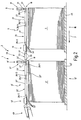
- FIG. 1 shows a device 1 for singulating of flat, stacked, flexible goods, namely Metal sheets, shown.
- the separating device 1 for separating the stacked goods which is part of an investor 3, one is not here explained further processing device downstream, with which the good further processed or be transported on.
- Further processing device for example a printing press or generally a freight transport device be.
- the for separating flat, to a stack 5 stacked goods serving singulator 1 comprises -in the transport direction (arrow 7) of the goods Seen- a decrease device 9, a transport device 11 and an overhead discharge line 13, the above and at a distance to the goods stack 5 are arranged.
- the goods stack 5 is one Assigned not shown stacking location 15.
- the vertical axis 14 is the of the stack of goods 5 opposite to the horizontal here extending transport direction (arrow 7) of the estate inclined by an angle ⁇ , in this embodiment 90 °.
- the vertical axis 14 is So perpendicular to the large area of the stacked Goods.
- the removal device 9 comprises a plurality of removal devices 17, the -in the transport direction (arrow 7) Seen side by side and at a distance from each other distributed over the width of the stack of goods 5 are arranged.
- a Hubsauger 18 is formed, which is a cylinder-piston unit with a cylinder 19, a movable therein Piston 20 and one with the piston 20th firmly connected piston rod 21 includes.
- At the free End of the piston rod 21 is one with a preferably Adjustable negative pressure acted upon Suction head 22 attached.
- the transport device 11 comprises in the embodiment 1 shows a first transport device 23 and one -in the transport direction (arrow 7) seen- the first transport device 23rd downstream, second transport device 25.
- Die Transport devices 23 and 25 have an identical Build up and operate as overhead suction belt sections educated. The following will be their structure based on the first transport device 23 explained in more detail.
- This includes at least one also referred to as a strand or conveyor belt endless belt 27, the over-in transport direction (arrow 7) seen at a distance from each other Rolls 28/1 and 28/2 is performed, of which at least one with the help of a not shown Drive can be acted upon by a drive and braking torque is.
- a suction box 29 is arranged, which with a not shown vacuum source connected and acted upon by a preferably adjustable negative pressure is.
- the inside of the suction box 29th prevailing negative pressure is via passage openings in the suction box 29 and in the endless belts 27th to the goods stack 5 facing surface 31st the endless belts 27 transmitted.
- the transport devices 23 and 25 are independent according to the invention controllable or controllable from each other, that is, that both the negative pressure in the suction boxes 29 as well as the rollers 28/1 and / or 28/2 associated drives independently are controllable or controllable.
- the overhead spout 13 includes a plurality of -in Transport direction (arrow 7) seen in succession arranged, a roller conveyor forming rollers 33, each with a partial circumference area in one With a vacuum acted upon suction hood 35th protrude.
- the rollers 33 are hollow cylindrical formed, wherein the jacket through holes has, so that in the interior of the suction hood 35th prevailing, preferably adjustable negative pressure on the through holes on the one with transporting good brought into plant partial circumference area the rollers 33 is transmitted. It is also possible that already by the through the gap between the rollers 33 to be transported Well transferred vacuum sufficient Attraction or adhesion force generated can be to keep the flat good. This also makes it possible, if necessary, roles without using through openings.
- the roles 33 are for rotation about their longitudinal central axis freely movable. Transverse to the transport direction are spaced apart preferably with several Spaced rollers 33 are arranged. The rollers 33 are not driven. At a not shown embodiment of the overhead discharge line 13 can be provided that at least one of the rollers 33, preferably several the rollers 33, a drive is associated with whose help the role (s) with a drive and Braking torque can be acted upon / are.
- the transport device 11 or the first and second Transport devices 23 and 25 and the overhead discharge path 13 arranged such that the in contact with the goods to be transported Surfaces of the suction belt sections (endless belts 27) or the rollers 33 approximately in one horizontally extending plane E are located. Further are all facilities of the separating device 1 in complete overlap position with arranged the goods stack 5. In top view on the Seen goods stack, so are the acceptance device 9 above the trailing edge region, the transport device 11 over the middle area and the overhead discharge line 13 above the leading edge area of the goods stack lying goods.
- the braking and acceleration processes of Transport devices 23, 25 are preferably so controlled or regulated that a Relative movement between the in-transit Good and the Saugriemenumblen the transport devices 23, 25 or the highest good of the Stacks of goods is avoided, so that a damage of the good, for example scratching or kinking, during lifting and transporting practically can be excluded. Should the good that means, at least in contact with the Saugriemenordern coming large area not be scratch sensitive, it is possible that, for example the braking process of the suction belt sections the transport devices 23, 25 already initiated when the trailing edge region of the complete removed from the pile, in the transport Guts still the respective Saugriemenstrekke partially overlapped and rests against this. hereby the separation speed can continue increase.
- the overhead discharge path is preferably always then used when particularly high singulation speeds are required. Should not Overhead discharge line can be used, so can one of the two transport devices 23, 25 or both transport devices 23, 25 -in the transport direction be extended accordingly, so that no or only small gaps in the transport route of the goods above the stack of goods consist.
- the singulation device is opened the acceptance device 9 is omitted.
- Their function is then another embodiment of the Transport devices 23, 25, as shown in the DE 198 32 847 are exercised.
- these transport devices is the negative pressure with which the suction belt distances be acted upon, in the transport direction Seen - sections controllable or regulated.
- For lifting the topmost gutter in its rear edge area from the stack is the above the Rear edge region arranged part of the suction belt route with a sufficiently high negative pressure applied.
- FIG. 2 shows another embodiment of the Singling device 1, located above and in overlapping position to two in the transport direction (Arrow 7) arranged in succession Goods stack 5 and 5 'is located. Same parts of the Separating device 1 are denoted by the same reference numerals so far as to the description Reference is made to FIG.
- the goods stack 5 lying on a pallet 45 is a first batch location 15 and the one on a pallet 45 'lying goods stack 5' a second Stapelort 15 'assigned.
- the stacking locations 15, 15 ' are respectively a lifting device not shown here for lifting the pallet 45 or 45 'with the on top of this stack of goods 5 and 5 'corresponding to the number taken from the stack assigned to the goods.
- the structure and functioning the lifting devices is known, for example from DE 198 11 166, so that these here are not described in detail.
- the separating device shown in Figure 2 1 includes one seen in the direction of transport first removal device 9, a first transport device 11 and a first overhead spout 13 associated with the first batch location 15 are, and a second acceptance device 9 ', a second transport device 11 'and a second Overhead discharge line 13 ', which is the second stacking location 15 'are assigned.
- the acceptance devices 9, 9 'and the transport devices 11, 11' overlap the goods stacks 5 and 5 ' completely while the identically trained Overhead discharge lines 13, 13 'the respective goods stack only partially overlap.
- the transport device 11 comprises two transport devices 23 and 25 and the transport device 11 'two transport devices 23' and 25 ', wherein the construction and the function of the transport devices 23 'and 25' of the transport devices 23 and 25 corresponds.
- the second stacking 15 'assigned Take-off device 9 ' is a bridging device 53 provided here as overhead suction belt route is formed and essentially has the same structure as the transport devices 23, 25, 23 'and 25'.
- the bridging device 53 thus comprises at least one Endless belt 27, usually several rollers 55 Guided, having passageways, in one Distance juxtaposed endless belts 57.
- Suction box provided with the aid of a preferably adjustable negative pressure on the goods stack facing surface of the endless belts 57 can be applied.
- the first removal device 17, the transport devices 23, 25 of the first transport device 11, the first overhead discharge line 13, the bridging device 53, the second removal device 17 ', the transport devices 23', 25 'of second transport device 11 'and the second Overhead discharge line 13 ' are in this embodiment arranged such that a substantially horizontally extending transport route for each one of the respective goods stack 5, 5 'lifted goods is formed. From Figure 2 is Furthermore, it can be seen that the spaces between designed as a modular units transport devices 23, 25, 23 ', 25', the picking devices 17, 17 ', the overhead run-off sections 13, 13 ', the bridging device 53 and the further processing device 49 only very small are.
- the further processing device 49 includes in the exemplary embodiment shown in Figure 2 a transport device only partially shown here, the two belt or conveyor belt sections includes. These are arranged in such a way that a closed nip is formed in the the goods are transported during transport.
- each one stacking site 15, 15 'associated facilities the separating device 1 corresponds that of the parts described with reference to FIG 1 or Facilities of the separating device 1, so that in the description Reference is made to FIG. The following will therefore be only the interaction of the stacking locations 15 and 15 'associated facilities of the separating device 1 explained in more detail.
- the overhead suction belt sections the transport devices 23 ' and 25 ', which are independent of each other and of the Transport devices 23, 25 controllable or adjustable are accelerated to transport speed, so that from the -in direction of transport viewed from the rear - goods stack 5 off single estate from the overhead run-off range 13 to the bridging device 53 and from there via the transport devices 23 'and 25' as well the overhead discharge line 13 'to the further processing device 49 is transported.
- the acceptance device 9, the Transport device 11, the overhead discharge line 13 and the bridging device 53 in be switched to a standby / standby state, as they are for a single transport from the Stacking 15 'arranged goods stack 5' off Goods are not needed.
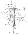
- FIG. 3 shows a further exemplary embodiment of the invention, the embodiment of the figure 1 corresponds.
- a Abdrückvorraum 60 is located, preferably as a pressure bar 61 is formed.
- the ejection bar 61 extends transverse to the transport direction (arrow 7).
- a piston / cylinder unit 62 can be a strip-shaped retaining element 63 down move it so that it is down over the transport plane protrudes.
- the retaining element 63 designed such that it is the good 41st not damaged or scratched.
- the device for separating from flat, stacked goods has their transport device more than two transporters, for example, three transport devices which can be independently controlled or regulated which makes a very fast and precise Lifting the top goods from the stack of goods as well its transport to the downstream facility is possible.
- a non-driven Outlet path between the transport devices 23 and 25 and 23 'and 25' respectively or in addition.
Landscapes
- Engineering & Computer Science (AREA)
- Mechanical Engineering (AREA)
- Sheets, Magazines, And Separation Thereof (AREA)
- De-Stacking Of Articles (AREA)
Description
- Figur 1
- eine Seitenansicht eines Ausführungsbeispiels der erfindungsgemäßen Vorrichtung zum Vereinzeln von flachigen, gestapelten Gütern,
- Figur 2
- eine Seitenansicht eines weiteren Ausführungsbeispiels mit zwei hintereinander angeordneten Guterstapeln mit entsprechend der anhand von Figur 1 beschriebenen Vereinzelungsvorrichtung und
- Figur 3
- eine Seitenansicht eines weiteren Ausführungsbeispiels einer erfindungsgemäßen Vorrichtung.
Claims (13)
- Vorrichtung (1) zum Vereinzeln von flächigen, gestapelten Gütern, die, vorzugsweise einer Verarbeitungsvorrichtung, mit Abstand zueinander und hintereinanderliegend zugeführt werden, mit einer Abnahmeeinrichtung (9;9') und einer Transporteinrichtung (11;11'), wobei der Abtransport der Güter in einer Transportrichtung erfolgt, die mit der Hochachse des Güterstapels (5;5') einen Winkel (α) einschließt, wobei die Transporteinrichtung (11;11') mindestens zwei Transportvorrichtungen (23,25;23',25') aufweist, die -in Transportrichtung gesehen- hintereinander und jeweils oberhalb des Güterstapels (5;5') sowie jeweils in Überlappungsposition zum Güterstapel (5;5') angeordnet sind und wobei die Transportvorrichtungen (23,25;23',25') unabhängig voneinander arbeitende Antriebe und eine Steuerung oder Regelung für die Antriebe aufweisen, bei denen die Transportgeschwindigkeiten der Transportvorrichtungen (23,25; 23',25') unabhängig voneinander einstellbar beziehungsweise regelbar sind.
- Vorrichtung nach Anspruch 1, dadurch gekennzeichnet, daß die Transportvorrichtungen (23,25;23',25') als Überkopf-Saugriemenstrecken ausgebildet sind.
- Vorrichtung nach Anspruch 1 oder 2, dadurch gekennzeichnet, daß die Transportvorrichtungen (23,25;23',25') als Überkopf-Magnetstrecken ausgebildet sind.
- Vorrichtungen nach einem der vorhergehenden Ansprüche, dadurch gekennzeichnet, daß die Abnahmeeinrichtung (9) mehrere Abnahmevorrichtungen (17) aufweist.
- Vorrichtung nach einem der vorhergehenden Ansprüche, dadurch gekennzeichnet, daß mindestens eine der Transportvorrichtungen (23,25;23',25') gleichzeitig die Funktion der Abnahmeeinrichtung oder einer Abnahmevorrichtung ausübt.
- Vorrichtung nach einem der vorhergehenden Ansprüche, dadurch gekennzeichnet, daß eine Abnahmevorrichtung (17) von mindestens einem Hubsauger (18) gebildet ist.
- Vorrichtung nach einem der vorhergehenden Ansprüche, dadurch gekennzeichnet, daß eine Abnahmevorrichtung von mindestens einem Hubmagneten gebildet ist.
- Vorrichtung nach einem der vorhergehenden Ansprüche, dadurch gekennzeichnet, daßdie Überkopfhaltefunktion der Transportvorrichtungen (23,25;23',25') unabhängig voneinander aktivierbar oder deaktivierbar ist.
- Vorrichtung nach einem der vorhergehenden Ansprüche, dadurch gekennzeichnet, daß -in Transportrichtung (Pfeil 7) gesehender Transporteinrichtung (11;11') eine Überkopf-Auslaufstrecke (13;13') nachgeschaltet ist, die zumindest teilweise in Überlappungsposition zum Güterstapel (5;5') liegt.
- Vorrichtung nach einem der vorhergehenden Ansprüche, dadurch gekennzeichnet, daß mindestens zwei -in Transportrichtung (Pfeil 7) des Guts gesehen- hintereinander angeordnete Güterstapel (5;5') vorgesehen sind, denen jeweils eine Abnahmeeinrichtung (9;9') und eine Transporteinrichtung (11;11') sowie vorzugsweise eine Überkopf-Auslaufstrecke (13;13') für die Güter zugeordnet sind.
- Vorrichtung nach Anspruch 10, dadurch gekennzeichnet, daß in dem Zwischenraum (51) zwischen den in einem Abstand zueinander angeordneten Güterstapel (5,5') eine Überbrückungseinrichtung (53) für die Güter angeordnet ist.
- Vorrichtung nach einem der vorhergehenden Ansprüche, dadurch gekennzeichnet, daß die Transportvorrichtungen (23,25;23',25') als Linearmotoren ausgebildet sind.
- Vorrichtung nach einem der vorhergehenden Ansprüche, gekennzeichnet durch die Transportrichtung mit der Hochachse des Güterstapels einen Winkel (α) im Bereich von 30° bis 150° einschließt.
Applications Claiming Priority (2)
| Application Number | Priority Date | Filing Date | Title |
|---|---|---|---|
| DE19911273A DE19911273C2 (de) | 1999-03-13 | 1999-03-13 | Verfahren und Vorrichtung zum Vereinzeln flächiger Güter |
| DE19911273 | 1999-03-13 |
Publications (3)
| Publication Number | Publication Date |
|---|---|
| EP1036752A2 EP1036752A2 (de) | 2000-09-20 |
| EP1036752A3 EP1036752A3 (de) | 2001-10-31 |
| EP1036752B1 true EP1036752B1 (de) | 2005-07-20 |
Family
ID=7900889
Family Applications (1)
| Application Number | Title | Priority Date | Filing Date |
|---|---|---|---|
| EP00105240A Expired - Lifetime EP1036752B1 (de) | 1999-03-13 | 2000-03-13 | Verfahren und Vorrichtung zum Vereinzeln flächiger Güter |
Country Status (4)
| Country | Link |
|---|---|
| US (1) | US6402134B1 (de) |
| EP (1) | EP1036752B1 (de) |
| DE (2) | DE19911273C2 (de) |
| ES (1) | ES2245625T3 (de) |
Families Citing this family (14)
| Publication number | Priority date | Publication date | Assignee | Title |
|---|---|---|---|---|
| JP3862084B2 (ja) * | 2003-10-30 | 2006-12-27 | ホリゾン・インターナショナル株式会社 | 冊子反転装置 |
| DE102007024916B4 (de) * | 2007-05-29 | 2009-08-06 | Eastman Kodak Co. | Transportmodul |
| DE102007042376B4 (de) | 2007-09-06 | 2021-06-02 | Koenig & Bauer Ag | Einrichten zum Führen von aus steifem Material bestehenden Bogen |
| WO2010037580A2 (en) * | 2008-09-30 | 2010-04-08 | Eastman Kodak Company | Sheet conveying device |
| JP5865099B2 (ja) * | 2012-01-31 | 2016-02-17 | キヤノン株式会社 | シート給送装置及び画像形成装置 |
| US9340377B2 (en) | 2013-03-12 | 2016-05-17 | United States Postal Service | System and method of automatic feeder stack management |
| US9044783B2 (en) | 2013-03-12 | 2015-06-02 | The United States Postal Service | System and method of unloading a container of items |
| US9056738B2 (en) | 2013-03-13 | 2015-06-16 | United States Postal Service | Anti-rotation device and method of use |
| US9061849B2 (en) | 2013-03-14 | 2015-06-23 | United States Postal Service | System and method of article feeder operation |
| JP6017355B2 (ja) * | 2013-03-21 | 2016-10-26 | 株式会社東芝 | 紙葉類の取出し装置 |
| JP6358200B2 (ja) * | 2015-09-02 | 2018-07-18 | コニカミノルタ株式会社 | 給紙装置、給紙方法及び画像形成システム |
| JP6642854B2 (ja) * | 2015-12-16 | 2020-02-12 | 株式会社リコー | シート材供給装置 |
| DE102017210690B4 (de) * | 2017-06-26 | 2021-04-08 | Koenig & Bauer Ag | Bogenanleger für eine Druckmaschine |
| DE102024103903A1 (de) * | 2024-02-12 | 2025-08-14 | Giesecke+Devrient Currency Technology Gmbh | Vorrichtung und Verfahren zum Vereinzeln von flächigen Elementen für die Herstellung von galvanischen Zellen |
Family Cites Families (20)
| Publication number | Priority date | Publication date | Assignee | Title |
|---|---|---|---|---|
| US3796424A (en) * | 1973-04-09 | 1974-03-12 | Philco Ford Corp | Document handling apparatus |
| DE2328007C2 (de) | 1973-06-01 | 1975-07-10 | Vits-Maschinenbau Gmbh, 4018 Langenfeld | Wende- und Vereinzelungsvorrichtung für den jeweils obersten Bogen eines Stapels |
| DE2431333A1 (de) | 1974-06-29 | 1976-01-08 | Weniger & Co | Verfahren und maschine zum abstapeln von plattenartigen guetern |
| US4157177A (en) * | 1975-12-10 | 1979-06-05 | Dr. Otto C. Strecker Kg. | Apparatus for converting a stream of partly overlapping sheets into a stack |
| US4451028A (en) | 1981-11-27 | 1984-05-29 | Xerox Corporation | Sheet feeding apparatus |
| JPS59177227A (ja) * | 1983-03-24 | 1984-10-06 | Nec Corp | 紙葉類給送装置 |
| FI71707C (fi) * | 1984-10-12 | 1987-02-09 | Raute Oy | Suglyfttransportoer foer foerflyttning av arkformiga foeremaol. |
| US4637589A (en) | 1985-05-16 | 1987-01-20 | Lin Ta C | Bi-section adjustable connector bridging an opened handrail |
| IT208064Z2 (it) | 1986-07-25 | 1988-03-31 | Grafica Torino S N C Di Lucian | Dispositivo di comando dei rulli di una piegatrice mediante cinghia dentata a doppia dentatura |
| US4768769A (en) * | 1986-12-19 | 1988-09-06 | Xerox Corporation | Low cost rear air knife top vacuum corrugation feeder |
| DD273416A1 (de) * | 1988-06-29 | 1989-11-15 | Polygraph Leipzig | Vorrichtung zum fliessenden transport von bogen |
| DE4005144C2 (de) * | 1990-02-17 | 1994-02-10 | Spiess Gmbh G | Bogenanleger |
| DE4205553A1 (de) | 1992-02-24 | 1993-08-26 | Siemens Nixdorf Inf Syst | Vorrichtung zum zufuehren von blaettern zu einem blattbehaelter und verfahren zur ansteuerung der vorrichtung |
| FR2696163B1 (fr) * | 1992-09-25 | 1994-11-04 | Cga Hbs | Dépileur d'articles plats incluant un dispositif de retaquage. |
| DE4323905A1 (de) * | 1993-07-16 | 1995-01-19 | Gremser Masch Franz | Vorrichtung zum Vereinzeln flächiger Gegenstände |
| DE29502103U1 (de) | 1995-02-09 | 1995-03-23 | NSM Magnettechnik GmbH, 59399 Olfen | Vorrichtung zur Einzelentnahme von Blechen o.dgl. von einem Stapel |
| DE19511296C2 (de) | 1995-03-28 | 1999-07-15 | Gremser Masch Franz | Vorrichtung zum Anheben und Abtransportieren flächiger Gegenstände |
| US5785311A (en) * | 1996-08-22 | 1998-07-28 | Pitney Bowes Inc. | Sheet separating and feeding device |
| DE19832847C2 (de) * | 1997-11-08 | 2002-11-21 | Ltg Holding Gmbh | Verfahren und Vorrichtung zum Vereinzeln flexibler, flächiger Gegenstände |
| EP0915041A1 (de) | 1997-11-08 | 1999-05-12 | LTG Holding GmbH | Verfahren und Vorrichtung zum Vereinzeln flexibler, flächiger Gegenstände |
-
1999
- 1999-03-13 DE DE19911273A patent/DE19911273C2/de not_active Expired - Fee Related
-
2000
- 2000-03-13 US US09/524,059 patent/US6402134B1/en not_active Expired - Fee Related
- 2000-03-13 DE DE50010726T patent/DE50010726D1/de not_active Expired - Lifetime
- 2000-03-13 ES ES00105240T patent/ES2245625T3/es not_active Expired - Lifetime
- 2000-03-13 EP EP00105240A patent/EP1036752B1/de not_active Expired - Lifetime
Also Published As
| Publication number | Publication date |
|---|---|
| ES2245625T3 (es) | 2006-01-16 |
| EP1036752A3 (de) | 2001-10-31 |
| DE19911273A1 (de) | 2000-09-21 |
| EP1036752A2 (de) | 2000-09-20 |
| DE50010726D1 (de) | 2005-08-25 |
| US6402134B1 (en) | 2002-06-11 |
| DE19911273C2 (de) | 2003-07-31 |
Similar Documents
| Publication | Publication Date | Title |
|---|---|---|
| DE69202534T2 (de) | Rollenakkumulator für Bogen. | |
| DE19845384B4 (de) | Vorrichtung zum Überführen flachliegender Gegenstände, insbesondere Faltschachteln | |
| DE69518209T2 (de) | Trennvorrichtung für gruppen geschindelter formulare | |
| DE4108397C2 (de) | Vorrichtung zur Bildung einer Folge von sich unterlappenden Gegenständen | |
| DE19955819A1 (de) | Vorrichtung zum Verlangsamen und Führen eines Bogens, und Verfahren hierfür | |
| DE69200010T2 (de) | Transport- und Stapelvorrichtung für flache Objekte. | |
| DE19911273C2 (de) | Verfahren und Vorrichtung zum Vereinzeln flächiger Güter | |
| EP2700599B1 (de) | Vorrichtung und Verfahren zum Abtrennen von einzelnen, flachen, biegbaren Gegenständen von der Unterseite eines Stapels | |
| DE4314832C1 (de) | Stapelvorrichtung für tafelförmige Güter | |
| EP2690040B1 (de) | Vorrichtung zum Abtrennen von einzelnen flachen, biegbaren Gegenständen von der Unterseite eines Stapels solcher Gegenstände | |
| EP0897890B1 (de) | Verfahren und Vorrichtung zur Erstellung eines gedrehten Produktstromes mit einem Eckengreifer | |
| DE19917405A1 (de) | Verfahren und Vorrichtung zum Vereinzeln flexibler flächiger Gegenstände | |
| EP2202158A1 (de) | Umreifungsvorrichtung und Verfahren zum Betrieb davon | |
| EP1801047A2 (de) | Stapelgreifer | |
| DE1611344A1 (de) | Papierbogenfalzmaschine | |
| DE102008060394B4 (de) | Vorrichtung und Verfahren zum Bilden eines Stroms sich überlappender Bögen oder Bogenstapel | |
| DE19856372B4 (de) | Bogentransportband | |
| DE102012019051A1 (de) | Transportvorrichtung für Bogen mit obenliegender Blasluftkammer | |
| EP1231176B1 (de) | Vorrichtung zum Zuführen von Druckprodukten in einen Förderkanal | |
| CH699389B1 (de) | Zwischenspeichervorrichtung und Stapeleinheit mit Zwischenspeichervorrichtung. | |
| EP4450434B1 (de) | Förderanlage für einen liegenden transport von blechtafeln | |
| EP1593626B1 (de) | Vorderkantenanleger | |
| EP3851281A1 (de) | Vorrichtung zum handhaben von druckplatten an einer druckmaschine | |
| EP0499691A1 (de) | Verfahren zur Verarbeitung von in einem Schuppenstrom ununterbrochen zugeführten Druckprodukten sowie Vorrichtung zur Ausübung des Verfahrens | |
| DE69618871T2 (de) | Artikelauswahl- und Verteilungsvorrichtung |
Legal Events
| Date | Code | Title | Description |
|---|---|---|---|
| PUAI | Public reference made under article 153(3) epc to a published international application that has entered the european phase |
Free format text: ORIGINAL CODE: 0009012 |
|
| AK | Designated contracting states |
Kind code of ref document: A2 Designated state(s): AT BE CH CY DE DK ES FI FR GB GR IE IT LI LU MC NL PT SE Kind code of ref document: A2 Designated state(s): DE ES GB IT |
|
| AX | Request for extension of the european patent |
Free format text: AL;LT;LV;MK;RO;SI |
|
| PUAL | Search report despatched |
Free format text: ORIGINAL CODE: 0009013 |
|
| AK | Designated contracting states |
Kind code of ref document: A3 Designated state(s): AT BE CH CY DE DK ES FI FR GB GR IE IT LI LU MC NL PT SE |
|
| AX | Request for extension of the european patent |
Free format text: AL;LT;LV;MK;RO;SI |
|
| 17P | Request for examination filed |
Effective date: 20020502 |
|
| AKX | Designation fees paid |
Free format text: AT BE CH CY DE DK ES FI FR GB GR IE IT LI LU MC NL PT SE |
|
| RBV | Designated contracting states (corrected) |
Designated state(s): DE ES GB IT |
|
| 17Q | First examination report despatched |
Effective date: 20030203 |
|
| GRAP | Despatch of communication of intention to grant a patent |
Free format text: ORIGINAL CODE: EPIDOSNIGR1 |
|
| GRAS | Grant fee paid |
Free format text: ORIGINAL CODE: EPIDOSNIGR3 |
|
| GRAA | (expected) grant |
Free format text: ORIGINAL CODE: 0009210 |
|
| AK | Designated contracting states |
Kind code of ref document: B1 Designated state(s): DE ES GB IT |
|
| REG | Reference to a national code |
Ref country code: GB Ref legal event code: FG4D Free format text: NOT ENGLISH |
|
| RIN1 | Information on inventor provided before grant (corrected) |
Inventor name: MICHEL, BJOERN |
|
| REF | Corresponds to: |
Ref document number: 50010726 Country of ref document: DE Date of ref document: 20050825 Kind code of ref document: P |
|
| GBT | Gb: translation of ep patent filed (gb section 77(6)(a)/1977) |
Effective date: 20050926 |
|
| REG | Reference to a national code |
Ref country code: ES Ref legal event code: FG2A Ref document number: 2245625 Country of ref document: ES Kind code of ref document: T3 |
|
| PLBE | No opposition filed within time limit |
Free format text: ORIGINAL CODE: 0009261 |
|
| STAA | Information on the status of an ep patent application or granted ep patent |
Free format text: STATUS: NO OPPOSITION FILED WITHIN TIME LIMIT |
|
| 26N | No opposition filed |
Effective date: 20060421 |
|
| REG | Reference to a national code |
Ref country code: DE Ref legal event code: R082 Ref document number: 50010726 Country of ref document: DE Representative=s name: GLEISS GROSSE SCHRELL & PARTNER PATENTANWAELTE, DE |
|
| REG | Reference to a national code |
Ref country code: GB Ref legal event code: 732E Free format text: REGISTERED BETWEEN 20120315 AND 20120321 |
|
| REG | Reference to a national code |
Ref country code: DE Ref legal event code: R081 Ref document number: 50010726 Country of ref document: DE Owner name: KBA-METALPRINT GMBH, DE Free format text: FORMER OWNER: LTG MAILAENDER GMBH & CO. KG, 70435 STUTTGART, DE Effective date: 20120326 |
|
| REG | Reference to a national code |
Ref country code: ES Ref legal event code: PC2A Owner name: KBA-METALPRINT GMBH Effective date: 20120510 |
|
| PGFP | Annual fee paid to national office [announced via postgrant information from national office to epo] |
Ref country code: IT Payment date: 20140321 Year of fee payment: 15 Ref country code: ES Payment date: 20140307 Year of fee payment: 15 |
|
| PGFP | Annual fee paid to national office [announced via postgrant information from national office to epo] |
Ref country code: GB Payment date: 20140320 Year of fee payment: 15 |
|
| GBPC | Gb: european patent ceased through non-payment of renewal fee |
Effective date: 20150313 |
|
| PG25 | Lapsed in a contracting state [announced via postgrant information from national office to epo] |
Ref country code: IT Free format text: LAPSE BECAUSE OF NON-PAYMENT OF DUE FEES Effective date: 20150313 |
|
| PG25 | Lapsed in a contracting state [announced via postgrant information from national office to epo] |
Ref country code: GB Free format text: LAPSE BECAUSE OF NON-PAYMENT OF DUE FEES Effective date: 20150313 |
|
| REG | Reference to a national code |
Ref country code: ES Ref legal event code: FD2A Effective date: 20160428 |
|
| PG25 | Lapsed in a contracting state [announced via postgrant information from national office to epo] |
Ref country code: ES Free format text: LAPSE BECAUSE OF NON-PAYMENT OF DUE FEES Effective date: 20150314 |
|
| PGFP | Annual fee paid to national office [announced via postgrant information from national office to epo] |
Ref country code: DE Payment date: 20170313 Year of fee payment: 18 |
|
| REG | Reference to a national code |
Ref country code: DE Ref legal event code: R119 Ref document number: 50010726 Country of ref document: DE |
|
| PG25 | Lapsed in a contracting state [announced via postgrant information from national office to epo] |
Ref country code: DE Free format text: LAPSE BECAUSE OF NON-PAYMENT OF DUE FEES Effective date: 20181002 |