EP1033273A2 - Klappverdeck für Kraftfahrzeuge mit einem äusseren Verdeckbezug und mindestens einer in diesem angeordneten Scheibe - Google Patents
Klappverdeck für Kraftfahrzeuge mit einem äusseren Verdeckbezug und mindestens einer in diesem angeordneten Scheibe Download PDFInfo
- Publication number
- EP1033273A2 EP1033273A2 EP00103614A EP00103614A EP1033273A2 EP 1033273 A2 EP1033273 A2 EP 1033273A2 EP 00103614 A EP00103614 A EP 00103614A EP 00103614 A EP00103614 A EP 00103614A EP 1033273 A2 EP1033273 A2 EP 1033273A2
- Authority
- EP
- European Patent Office
- Prior art keywords
- bead
- roof according
- edge
- bead element
- folding roof
- Prior art date
- Legal status (The legal status is an assumption and is not a legal conclusion. Google has not performed a legal analysis and makes no representation as to the accuracy of the status listed.)
- Withdrawn
Links
- 239000011521 glass Substances 0.000 title description 6
- 239000000463 material Substances 0.000 claims abstract description 9
- 239000012508 resin bead Substances 0.000 claims abstract description 8
- 239000011324 bead Substances 0.000 claims description 111
- 230000002787 reinforcement Effects 0.000 claims description 18
- 238000010079 rubber tapping Methods 0.000 claims description 9
- 238000007789 sealing Methods 0.000 claims description 8
- 239000011347 resin Substances 0.000 claims description 5
- 229920005989 resin Polymers 0.000 claims description 5
- 238000005266 casting Methods 0.000 claims description 3
- 239000002184 metal Substances 0.000 claims description 3
- 230000000087 stabilizing effect Effects 0.000 claims description 2
- 230000013011 mating Effects 0.000 claims 1
- 239000004744 fabric Substances 0.000 description 8
- 230000008901 benefit Effects 0.000 description 5
- 230000005855 radiation Effects 0.000 description 3
- 230000000295 complement effect Effects 0.000 description 2
- 230000002093 peripheral effect Effects 0.000 description 2
- 229920003023 plastic Polymers 0.000 description 2
- 239000000853 adhesive Substances 0.000 description 1
- 238000004026 adhesive bonding Methods 0.000 description 1
- 230000001070 adhesive effect Effects 0.000 description 1
- 238000004873 anchoring Methods 0.000 description 1
- 230000004888 barrier function Effects 0.000 description 1
- 238000005452 bending Methods 0.000 description 1
- 230000000903 blocking effect Effects 0.000 description 1
- 230000008859 change Effects 0.000 description 1
- 238000010276 construction Methods 0.000 description 1
- 238000013461 design Methods 0.000 description 1
- 238000011161 development Methods 0.000 description 1
- 230000018109 developmental process Effects 0.000 description 1
- 229920002457 flexible plastic Polymers 0.000 description 1
- 239000006260 foam Substances 0.000 description 1
- 230000006872 improvement Effects 0.000 description 1
- 238000003780 insertion Methods 0.000 description 1
- 230000037431 insertion Effects 0.000 description 1
- 230000010354 integration Effects 0.000 description 1
- 230000003287 optical effect Effects 0.000 description 1
- 238000009958 sewing Methods 0.000 description 1
- 239000005341 toughened glass Substances 0.000 description 1
- 238000012549 training Methods 0.000 description 1
- 230000007704 transition Effects 0.000 description 1
Images


Classifications
-
- B—PERFORMING OPERATIONS; TRANSPORTING
- B60—VEHICLES IN GENERAL
- B60J—WINDOWS, WINDSCREENS, NON-FIXED ROOFS, DOORS, OR SIMILAR DEVICES FOR VEHICLES; REMOVABLE EXTERNAL PROTECTIVE COVERINGS SPECIALLY ADAPTED FOR VEHICLES
- B60J1/00—Windows; Windscreens; Accessories therefor
- B60J1/18—Windows; Windscreens; Accessories therefor arranged at the vehicle rear
- B60J1/1807—Windows; Windscreens; Accessories therefor arranged at the vehicle rear movable for vehicles with convertible top
- B60J1/1815—Windows; Windscreens; Accessories therefor arranged at the vehicle rear movable for vehicles with convertible top non-adjustably mounted in and moving with the soft-top cover
-
- B—PERFORMING OPERATIONS; TRANSPORTING
- B60—VEHICLES IN GENERAL
- B60J—WINDOWS, WINDSCREENS, NON-FIXED ROOFS, DOORS, OR SIMILAR DEVICES FOR VEHICLES; REMOVABLE EXTERNAL PROTECTIVE COVERINGS SPECIALLY ADAPTED FOR VEHICLES
- B60J10/00—Sealing arrangements
- B60J10/90—Sealing arrangements specially adapted for non-fixed roofs, e.g. foldable roofs or removable hard-tops
Definitions
- the invention relates to a folding roof for motor vehicles such as convertibles or the like, with an outer cover and at least one in a cutout the same arranged pane, which with the outer fabric mechanically strong and tight by means of at least one cast resin bead element is connected, the edge of the cutout in the outer cover and the edge of the disk are bordered by bead element sections.
- the invention is based on DE 197 24 592 C1.
- This document discloses a vehicle top in which the top or rear window with a convertible top surface element using a PUR cast resin bead element is mechanically tight and tightly connected, which is the edge of the top surface element and the adjacent edge of the top or rear window on both sides, i.e. mechanically tight and tightly enclosed on the inside and outside.
- the two top surface elements are used to implement such a top inserted into a suitably designed tool, the tool tightly sealed and in the mold cavity in the tool introduced the PUR casting resin. After the reaction sequence of the PUR cast resin, the mold is opened and the corresponding hood or Hood part removed from the mold.
- the main advantage of such a convertible top design is that the two top surface elements without complex structural measures, such as in particular gluing or sewing, can be connected to one another, and also in a visually very appealing way.
- the integration a pane in the cutout of a convertible top fabric using a PUR cast resin bead element is also particularly special for tempered glass panes Advantage that is basically not like flexible plastic discs in the Canopy can be sewn in.
- the object of the invention is a folding roof for vehicles to create the advantages of the cast resin bead element connection picks up between convertible top fabric and window, however creates an easy way to replace the disc at any time.
- the invention solves this problem with the features of the independent Claim and is accordingly characterized in that the cut-out edge the outer cover of the convertible top and the edge of the window on the other hand, each with its own bead element forming a frame are bordered that the two bead elements are provided with joining surfaces are, by means of which they can be coupled with one another with a precise fit, and that the two Bead elements are held together by means of releasable connecting means.
- the essential core of the solution according to the invention is therefore in that you cut the edge of the outer cover with a provides the first bead element frame and that one with the edge of the pane equips its own, second bead element frame, these two Frames are designed by means of joining surfaces so that they fit together perfectly can connect, connecting means, in the simplest case screws, hold the two bead element frames together.
- the two frames are made of cast resin elements, in particular cast from PUR are formed, the joining of the two frame parts or bead elements so cleverly that any additional sealing or sealing elements can be completely dispensed with. Thanks to the detachable Lanyard, it is possible to change the disc at any time, since the loosening of the connecting means separates the two bead element frame bodies easily results.
- the invention also has the further advantage that the two Top surface elements - glass pane and top fabric - not together and placed in a mold exactly aligned to each other but that each of these two parts individually, i.e. so the inside circumferential edge of a cutout in the top fabric on the one hand and the outer edge the glass pane, on the other hand, in a corresponding form with each associated bead element frame can be provided.
- connection itself is of the simplest nature.
- Threaded bushes for receiving Threaded shafts of the connecting means are cast in. This is a Solution that is particularly recommended when you are not - like one
- At least one of the Bead elements are provided with stabilizing reinforcement elements
- Metal strips can exist, which in the bead element in question are cast in.
- the reinforcement elements can be at least partially one if necessary, follow the angular cross-sectional contour of the bead element in question and so far form a stiffening core.
- the reinforcement inserts on the screw connection can also be used participate as they have openings through which the screw connection means cooperate thread-wise. That way Avoid that sharp thread flanks possibly the material of the Bead elements could damage if they interact directly and only with them would.
- one of the Bead elements have a channel profile which is essentially U-shaped in cross section formed and the other bead element a substantially T-shaped Has cross section, with a strip-shaped projection, so that the two Interlocking bead elements in the manner of a tongue and groove connection.
- the bead elements with their joining surfaces form a kind of labyrinth seal airtight and moistureproof to each other.
- Bead elements on the sides of the outer side facing the vehicle interior Convertible top cover or the pane are arranged such that they are from edge parts of the outer cover and / or the window are covered.
- the material of the bead elements is at the same time removed from direct UV radiation. Even if there is a bead element located just behind the glass of the pane, it should be noted that liability of the bead element material on the glass pane, a primer is used, as is generally used for glued-in panes. Such a Primer is known to have UV blocking properties to protect the Adhesive.
- Fig. 1 shows a window as viewed from the vehicle interior 10, in particular the rear window of a convertible.
- the disc edge 11 is encircled by a PUR cast resin bead element 12, which further is described in detail below.
- a PUR cast resin bead element 12 which further is described in detail below.
- Of the outer cover 13 is only one circumferential narrow stripe shown.
- the edge 14 of the top cover 13 cutout is also made of a PUR cast bead element 15 bordered.
- the two cast resin bead elements 12 and 15 each form one Framework of high inherent rigidity and are at least more extensive Coverage with respect to the viewing direction in Fig. 1 designed so that it are fit into one another with a precise fit, connecting means 16, in particular Screws or screw connections, the two bead elements 12 and 15 firmly connect with each other.
- Fig. 2 shows the essential elements of the connection area between Washer 11 and outer convertible top cover 13 in its individual parts. Clear can be seen how the bead element 12 on the outer circumferential edge 11 of the disc 10 is connected and like the second bead element 15 the cutout edge 14 of the outer cover 13 is connected.
- the bead element 12 has an approximately U-shaped shape in cross section with a central web 17 and two U-legs 18 and 19. Between these Legs 18 and 19 have a substantially rectangular groove 20.
- the one on top of the other to directed contours of the two bead elements 12 and 15 have a matching, complementary course, so that the whole each with 24 and 25 designated joining surfaces fit into each other find when the two bead members 12 and 15 are assembled.
- the joining surfaces are due to their respective Also suitable and destined to form a kind of labyrinth seal, once the two bead elements 12 and 15 are fixed with a particular one connecting means 16 designed as screws are held together, as shown in Fig. 3.
- Screw shafts 26 each have a bore 27 in the disk 10 assigned reach through the inner bead element 12 and into a screw shaft receptacle 28 engage, which is mounted in the second outer bead member 15 is.
- the screw heads 29 are sunk in one Countersink 30 on the top of the bead element facing the vehicle interior 12. If necessary, the visible part of the screw head 19 also by means of a cap which is color-matched to the bead element 12 be hidden - which is not shown - so that the connecting means are invisible themselves.
- the screw receptacle 28 in the bead element 14 is as Blind hole formed so that this completely to the outside of the top is covered by the material of the bead element 15.
- Fig. 2 further shows that the bead element 15 is still with an edge strip 31 is provided, which in the assembled state according to FIG. 3 is one Outer edge 32 of the other bead element 12 nestles and on the outer surface the disc 10 is seated.
- the edge bar 31 serves on the one hand for additional Sealing of the joint surface area, so takes part in the labyrinth seal part in the sense of a dirt deflector, and on the other hand ensures one very precise and sharp peripheral edge as visible from the outside Pane surround.
- the two bead elements 12 and 15 are still with reinforcement inserts 32 and 33 provided. These are metal strips, during the casting process into the PUR material of the respective bead element 12 or 15 would be introduced.
- the U-shaped Bead element 12 is also essentially this "stiffening core" 32 U-shaped.
- the reinforcement insert 33 partly follows the cross-sectional profile of the T-shaped bead member 23 by the embodiment Is Z-shaped.
- Both reinforcement inserts 32 and 33 are designed so that they also contribute to the attachment of the two elements.
- this serves for the interior of the vehicle facing outer surface of the reinforcement insert 32 in the bead element 12 of the immediate Support the lower surface of the screw head 29, so that Plastic material of the bead element cannot be damaged.
- the leg of the reinforcement insert 33, designated 34, in the bead element 15 is provided on the end face of the strip-shaped projection 21 and here has an opening with an inner diameter which is approximately that Corresponds to the inner diameter of the connecting means receptacle 28.
- the self-tapping Screw 16 penetrates with its thread tips 26 also self-tapping into this metallic reinforcement element so that the screw stop thereby improving overall. This is illustrated right in FIG. 3 Good. This illustration also shows that the strip-shaped projection 21 is shorter than the depth of the groove 20, so that a tolerance-compensating in the clamping area Gap 35 may be present.
- the reinforcement elements 32 and 33 are longitudinal the beads 12 and 15 extending strips. These follow the arched and, if necessary, a curved course of the edge of the pane and of the convertible top. Only in the radii designated by 36 in FIG. 1 these reinforcement elements are interrupted, i.e. there are four individual reinforcement element sections arranged in the respective bead elements 12 and 15.
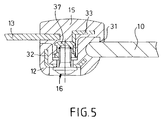
- FIGS. 4 and 5 differs from that the first embodiment shown in FIGS. 2 and 3 essentially by that here as a connection means not self-tapping, but normal threaded screws 16 are used.
- a connection means not self-tapping, but normal threaded screws 16 are used.
- To their threaded shafts 26 to be securely anchored in the other bead element 15 are in this at intervals spacings corresponding to the screw connections 37 let in. In the arrangement area of each such threaded bushing 37 the reinforcement insert 33 is released here.
- the bead elements 12 and 15 are considered the arrangement is not visible from the top or vehicle exterior, because they are from the primed pane edge 11 and / or the edge 14 of the top cover 13 are covered.
- FIG. 6 shows the essential elements based on a third embodiment the connection area between the pane 11 and the outer cover 13 in its individual parts. It can clearly be seen how the bead element 12 is connected to the outer peripheral edge 11 of the disc 10 and how the second bead element 15 with the cutout edge 14 of the outer cover 13 is connected.
- the bead element 12 has an approximately T-shaped shape in cross section with a central web 17 and two T-legs 18 and 19.
- the one assigned to the outer convertible top cover 13 Bead element 15 in cross-section has an essentially U-shape with two U-legs 22 and 23.
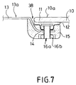
- the contours of the two facing each other Bead elements 12 and 15 have a complementary match Course on, so that in their entirety designated 24 and 25 respectively Find the joining surfaces in one another with a perfect fit when the two bead elements 12 and 15 are put together. As you can see, they are Due to their respective course, joining surfaces are also suitable and determined form a kind of labyrinth seal as soon as the two bead elements 12 and 15 held together with connecting means 16a, 16b as shown in FIG. 7.
- the connecting means 16a, 16b each consist of a bead element in the disk-side 12 cast-in and non-rotatably held threaded bolts 16a and a matching mother 16b.
- the threaded shaft 26 of the threaded bolt 16a each Bore 27 in the inner bead element associated with the top cover edge 14 15 into an expanded receptacle 28 for the mother 16b.
- the nut 16b is received completely recessed in the final assembly state, and there is still plenty of room for the insertion of a nut wrench, with which the screw connection 16a, 16b can be handled.
- top cover edge 14 is behind the Edge of the glass sheet 10 and retracted behind the bead member 12.
- the result is an optically optimized view insofar as the outer surfaces 10a the disc 10 and 13a of the convertible top cover 13 to lie flush in one plane come. There is only a small gap between them kind of a shadow gap 38.
- Bores 28 are machined in the central web 17 of the bead element 15 for self-tapping screws 16a, the corresponding through holes 27 reach through in the bead element 12.
- a special feature of the second embodiment is that the Convertible top cover edge 14 forms a fold 39, which around the outer as well longer leg 19 of the two T-legs 18, 19 is folded.
- the flipped Bending section 40 comes to rest on the edge 11 of the pane 10th
- This edition can take place immediately or with the interposition of a thin sealing strand 41, e.g. a caterpillar made of sealing foam that The edge of the pane is glued or adheres to it.
- a thin sealing strand 41 e.g. a caterpillar made of sealing foam that The edge of the pane is glued or adheres to it.
- This embodiment is also characterized by an optically elegant Fitting the pane 10 into the cutout of the convertible top cover 13. Also only these two parts are visible from the outside, whereas the bead elements 12, 15 both the view and the influence of harmful UV radiation are withdrawn.
- the bead elements are preferably made of a PUR cast resin system built up and have a hardness of the order of 40-60 Shore D, so that it is not rubber-like soft, but relatively hard and dimensionally stable are.
Landscapes
- Engineering & Computer Science (AREA)
- Mechanical Engineering (AREA)
- Window Of Vehicle (AREA)
- Seal Device For Vehicle (AREA)
- Body Structure For Vehicles (AREA)
- Securing Of Glass Panes Or The Like (AREA)
Abstract
Description
- Fig. 1
- eine Innenansicht auf einen Heckscheibenbereich eines Fahrzeugverdecks,
- Fig. 2
- die wesentlichen Teile eines Verdecks im Verbindungsbereich zwischen dem Verdeckstoff und einer Scheibe, im Querschnitt betrachtet,
- Fig. 3
- die Anordnung nach Fig. 2 im montierten Zustand,
- Fig. 4
- eine der Fig. 2 entsprechende Darstellung einer zweiten Ausführungsform und
- Fig. 5
- diese Ausführungsform im montierten Zustand.
- Fig. 6
- eine dritte Ausführungsform in der Darstellung entsprechend Fig. 2,
- Fig. 7
- die Anordnung nach Fig. 6 im montierten Zustand,
- Fig. 8
- eine wiederum der Fig. 2 entsprechende Darstellung einer vierten Ausführungsform und
- Fig. 9
- diese Ausführungsform im montierten Zustand.
Claims (25)
- Klappverdeck für Kraftfahrzeuge wie Kabrioletts od.dgl., mit einem äußeren Verdeckbezug (13) und mindestens einer in einem Ausschnitt desselben angeordneten Scheibe, (10) die mit dem äußeren Verdeckstoff (13) mittels wenigstens eines Gießharz-Wulstelements (12) mechanisch fest und dicht verbunden ist, wobei der Rand (14) des Ausschnitts im äußeren Verdeckbezug (13) und der Rand (11) der Scheibe (10) von Wulstelementabschnitten eingefaßt sind, dadurch gekennzeichnet, dass der Ausschnittsrand (14) des äußeren Verdeckbezugs (13) einerseits und der Rand (11) der Scheibe (10) andererseits von jeweils einem eigenen, einen Rahmen bildenden Wulstelement (12; 15) eingefaßt sind, dass die beiden Wulstelemente (12, 15) mit Fügeflächen (24, 25) versehen sind, über die sie paßgenau miteinander kuppelbar sind, und dass die beiden Wulstelemente (12, 15) mittels lösbarer Verbindungsmittel (16) zusammengehalten sind.
- Klappverdeck nach Anspruch 1, dadurch gekennzeichnet, dass die Verbindungsmittel (16), wie Schrauben, von der Innenseite des Verdecks her betätigbar sind, das innere Wulstelement (12) durchgreifen und im äußeren Wulstelement (15) verankerbar sind.
- Klappverdeck nach Anspruch 2, dadurch gekennzeichnet, dass das innere Wulstelement (12) der Scheibe (10) und das äußere Wulstelement (15) dem äußeren Verdeckbezug (13) zugeordnet ist.
- Klappverdeck nach Anspruch 2 oder 3, dadurch gekennzeichnet, dass in das äußere Wulstelement (15) Gewindebuchsen (37) zur Aufnahme von Gewindeschäften (26) der Verbindungsmittel (16) mit eingegossen sind.
- Klappverdeck nach Anspruch 2 oder 3, dadurch gekennzeichnet, dass die Schrauben (16) selbstschneidend ausgebildet sind und mit ihren Gewindeschäften (26) jeweils in eine Aufnahmeöffnung (28) des äußeren Wulstelements (15) eingreifen.
- Klappverdeck nach einem der vorhergehenden Ansprüche, dadurch gekennzeichnet, dass zumindest eines der Wulstelemente (12; 15) mit stabilisierenden Bewehrungselementen (32, 33) versehen ist.
- Klappverdeck nach Anspruch 6, dass die Bewehrungselemente (32, 33) aus Metallstreifen bestehen, die in das betreffende Wulstelement (12, 15) mit eingegossen sind.
- Klappverdeck nach Anspruch 6 oder 7, dadurch gekennzeichnet, dass die Bewehrungselemente (32, 33) zumindest teilweise einer ggf. winkligen Querschnittskontur des betreffenden Wulstelements (12; 15) folgen und insoweit einen Versteifungskern ausbilden.
- Klappverdeck nach einem der Ansprüche 5 bis 8, dadurch gekennzeichnet, dass die Bewehrungselemente (32, 33) Öffnungen aufweisen, mit denen die Schraub-Verbindungsmittel (16) gewindemäßig zusammenwirken.
- Klappverdeck nach einem der vorhergehenden Ansprüche, dadurch gekennzeichnet, dass eines der Wulstelemente (12) ein im Querschnitt im wesentlichen U-förmiges Rinnenprofil ausbildet und das andere Wulstelement (15) einen im wesentlichen T-förmigen Querschnitt aufweist mit einem leistenförmigen Vorsprung (21), so dass die beiden Wulstelemente (12, 15) nach Art einer Nut-Feder-Verbindung ineinandergreifen.
- Klappverdeck nach Anspruch 10, dadurch gekennzeichnet, dass das den leistenförmigen Vorsprung (21) aufweisende Wulstelement (15) mit Schultern (22, 23) versehen ist, die zur Anlage an Gegenflächen des anderen Wulstelements (15) dienen, welche die Stirnflächen der U-Schenkel (18, 19) ausbilden.
- Klappverdeck nach einem der vorhergehenden Ansprüche, dadurch gekennzeichnet, dass das dem äußeren Verdeckbezug (13) zugeordnete Wulstelement (15) eine Randleiste (31) aufweist, die auf der Scheibenaußenseite den die Scheibe (10) einfassenden Rand des anderen Wulstelements (12) übergreift.
- Klappverdeck nach einem der vorherigen Ansprüche, dadurch gekennzeichnet, dass die Wulstelemente (12, 15) mit ihren Fügeflächen (24, 25) unter Bildung einer Art Labyrinthdichtung luft- und feuchtigkeitsdicht aneinanderliegen.
- Klappverdeck nach einem der vorhergehenden Ansprüche, dadurch gekennzeichnet, dass die Aufnahmen (28) für die Verbindungsmittel (16) im äußeren Wulstelement (15) als auf dessen Außenseite von Gießharz überdeckte Sackbohrungen ausgeführt sind.
- Klappverdeck nach einem der vorhergehenden Ansprüche, dadurch gekennzeichnet, dass im inneren Wulstelement (12) auf dessen Innenseite Einsenkungen (30) zur versenkten Aufnahme der Verbindungsmittel-Köpfe (29) ausgebildet sind.
- Klappverdeck nach Anspruch 1, dadurch gekennzeichnet, dass die Wulstelemente (12, 15) auf den zum Fahrzeuginnern weisenden Seiten des äußeren Verdeckbezugs (13) bzw. der Scheibe (10) derart angeordnet sind, dass sie von Randpartien des äußeren Verdeckbezugs (13) und/oder der Scheibe (10) abgedeckt sind.
- Klappverdeck nach Anspruch 16, dadurch gekennzeichnet, dass sich der Ausschnittsrand (14) des Verdeckbezugs (13) und der Rand (11) der Scheibe (10) überlappen.
- Klappverdeck nach Anspruch 16 oder 17, dadurch gekennzeichnet, dass der Ausschnittsrand (14) des Verdeckbezugs (13) hinter den Rand (11) der Scheibe (10) eingezogen ist.
- Klappverdeck nach Anspruch 18, dadurch gekennzeichnet, dass der Ausschnittsrand (14) des Verdeckbezugs (13) in einem Wulstelement (15) angeordnet ist, das zumindest einen sich hinter dem Scheibenrand (11) und hinter einem an diesem angebrachten Wulstelement (12) erstreckenden Abschnitt aufweist.
- Klappverdeck nach Anspruch 19, dadurch gekennzeichnet, dass die Außenflächen von Verdeckbezug (13) und Scheibe (10) im wesentlichen in gleicher Ebene, also bündig, angeordnet sind und im sichtbaren Grenzbereich lediglich eine Art Schattenfuge (38) ausbilden.
- Klappverdeck nach einem der Ansprüche 16 bis 20, dadurch gekennzeichnet, dass sich das scheibenseitige Wulstelement (15) im wesentlichen nur auf einer Seite der Scheibe (10) längs deren umlaufenden Randes (11) erstreckt.
- Klappverdeck nach Anspruch 16 oder einem darauf folgenden, dadurch gekennzeichnet, dass der Ausschnittsrand (14) des Verdeckbezugs (13) einen von einem Abschnitt des Wulstelements (15) ausgefüllten Umbug (39) ausbildet, dessen innerer Umbugabschnitt (40) zur mindestens mittelbaren Anlage auf dem Scheibenrand (11) bestimmt ist.
- Klappverdeck nach Anspruch 22, dadurch gekennzeichnet, dass der innere Umbugabschnitt (40) unter Zwischenlage eines Dichtstreifens (41) auf der Scheibenrandfläche (11) aufliegt.
- Klappverdeck nach einem der Ansprüche 16 bis 23, dadurch gekennzeichnet, dass im scheibenseitigen Wulstelement (12) Schraubenbolzen (16a) undrehbar eingegossen sind, die jeweils das verdeckbezugseitige Wulstelement (15) durchgreifen und dort in eine erweiterte Ausnehmung (28) eintauchen, in der eine Mutter (16b) versenkt Platz findet sowie der Werkzeugansatz eines Steckschlüssels paßt.
- Klappverdeck nach einem der Ansprüche 16 bis 24, dadurch gekennzeichnet, dass das verdeckbezugseitige Wulstelement (15) mit Aufnahmen (28) für selbstschneidende Schrauben (16a) bzw. Gewindebohrungen für Schraubbolzen ausgerüstet ist, die das scheibenseitige Wulstelement (12) vom Fahrzeuginnern her durchgreifen.
Applications Claiming Priority (4)
| Application Number | Priority Date | Filing Date | Title |
|---|---|---|---|
| DE19909139A DE19909139A1 (de) | 1999-03-03 | 1999-03-03 | Klappverdeck für Kraftfahrzeuge mit einem äußeren Verdeckbezug und mindestens einer in diesem angeordneten Scheibe |
| DE19909139 | 1999-03-03 | ||
| DE19923544A DE19923544A1 (de) | 1999-03-03 | 1999-05-21 | Klappverdeck für Kraftfahrzeuge mit einem äußeren Verdeckbezug und mindestens einer in diesem angeordneten Scheibe |
| DE19923544 | 1999-05-21 |
Publications (2)
| Publication Number | Publication Date |
|---|---|
| EP1033273A2 true EP1033273A2 (de) | 2000-09-06 |
| EP1033273A3 EP1033273A3 (de) | 2001-06-20 |
Family
ID=26052147
Family Applications (1)
| Application Number | Title | Priority Date | Filing Date |
|---|---|---|---|
| EP00103614A Withdrawn EP1033273A3 (de) | 1999-03-03 | 2000-02-21 | Klappverdeck für Kraftfahrzeuge mit einem äusseren Verdeckbezug und mindestens einer in diesem angeordneten Scheibe |
Country Status (3)
| Country | Link |
|---|---|
| US (1) | US6263627B1 (de) |
| EP (1) | EP1033273A3 (de) |
| DE (1) | DE19923544A1 (de) |
Cited By (3)
| Publication number | Priority date | Publication date | Assignee | Title |
|---|---|---|---|---|
| EP1780067A3 (de) * | 2005-11-01 | 2008-06-11 | Nippon Sheet Glass Company, Limited | Dichtung für eine feste Scheibe |
| WO2010025789A1 (de) * | 2008-09-04 | 2010-03-11 | Meteor Gummiwerke K. H. Bädje Gmbh & Co.Kg | Kfz-formteil mit dichtung |
| CN103522872A (zh) * | 2012-07-06 | 2014-01-22 | 德科马(德国)有限责任公司 | 窗玻璃紧固件 |
Families Citing this family (29)
| Publication number | Priority date | Publication date | Assignee | Title |
|---|---|---|---|---|
| US7082736B2 (en) * | 1998-11-04 | 2006-08-01 | Transit Care, Inc. | Process for retrofitting an existing bus window having rubber seals with metal members that define a retention space for a sacrificial member |
| US6408574B1 (en) | 1998-11-04 | 2002-06-25 | Transit Care, Inc. | Quick release sacrificial shield and window assembly |
| US7254927B1 (en) | 1998-11-04 | 2007-08-14 | Transit Care, Inc. | Process for retrofitting an existing bus window having rubber seals with metal members that define a retention space for a sacrificial member |
| DE20006330U1 (de) * | 2000-04-07 | 2001-05-23 | BBG Braunsberger GmbH & Co. KG, 87719 Mindelheim | Glasscheibe mit Kunststoff-Umrandung |
| DE10163709B4 (de) * | 2001-12-21 | 2006-05-24 | Arvinmeritor Gmbh | Modulartiges Fahrzeugdach |
| DE10202425A1 (de) * | 2002-01-22 | 2003-08-07 | Cts Fahrzeug Dachsysteme Gmbh | Kraftfahrzeug-Faltverdeck |
| US6647677B1 (en) * | 2002-02-11 | 2003-11-18 | Allen Berger, Jr. | Window assembly for garage doors |
| US6705742B1 (en) * | 2002-08-23 | 2004-03-16 | Insight Lighting, Inc. | System for directing light from a luminaire |
| US7152906B1 (en) | 2002-10-11 | 2006-12-26 | Transit Care, Inc. | Quick change window assembly |
| CA2500666C (en) | 2002-10-11 | 2013-07-16 | Transit Care, Inc. | Quick change window assembly |
| US6935677B2 (en) * | 2003-06-11 | 2005-08-30 | Edscha Roof Systems Inc. | Backlite retention system |
| USD569709S1 (en) * | 2007-03-20 | 2008-05-27 | Robert King | Combined bracket and mounting element for mounting illuminated glass |
| USD568722S1 (en) * | 2007-03-20 | 2008-05-13 | Robert King | Combined bracket and mounting element for mounting illuminated glass |
| DE102008034400A1 (de) * | 2008-07-23 | 2010-01-28 | Richard Fritz Gmbh + Co. Kg | Anordnung einer feststehenden Scheibe an einem Karosserieflansch sowie Befestigungsclip zur Montage der feststehenden Scheibe |
| DE102008058465A1 (de) | 2008-11-21 | 2010-05-27 | Wilhelm Karmann Gmbh | Verdeck für ein Fahrzeug mit einer an einen flexiblen Verdeckbezug angeordneten Scheibe |
| IL198882A0 (en) * | 2009-05-21 | 2010-02-17 | Plasan Sasa Ltd | Externally mounted window system, a bracket thereof and a method for its assembly |
| DE202010016886U1 (de) * | 2010-12-21 | 2011-03-10 | Henniges Automotive Gmbh & Co. Kg | Befestigung einer mit einem umspritzten Randprofil ausgerüsteten Glasscheibe, insbesondere Automobilglasscheibe |
| DE102011012256A1 (de) * | 2011-02-24 | 2012-08-30 | Daimler Ag | Fensterelement für eine Seitentür, insbesondere eine hintere Seitentür, eines Kraftwagens |
| JP5796734B2 (ja) * | 2011-05-13 | 2015-10-21 | 日立化成株式会社 | バックドア用アウターパネル |
| DE102011110451B4 (de) * | 2011-08-17 | 2022-05-12 | Webasto SE | Scheibenbefestigung einer Scheibe an einem Verdeckbezug eines Fahrzeugverdecks |
| US9033403B2 (en) * | 2013-10-04 | 2015-05-19 | GM Global Technology Operations LLC | Vehicle, an assembly for the vehicle and a method of assembling the vehicle |
| DE202013009456U1 (de) * | 2013-10-23 | 2015-01-26 | GM GLOBAL TECHNOLOGY OPERATION LLC (n. d. Ges. d. Staates Delaware) | Seitenscheibe einer Seitenwandbaugruppe einer Kraftfahrzeugkarosserie |
| JP6449793B2 (ja) * | 2014-02-13 | 2019-01-09 | 日本板硝子株式会社 | 自動車用窓ガラスのブラケット |
| US20160362071A1 (en) * | 2015-06-09 | 2016-12-15 | GM Global Technology Operations LLC | Semi-integral cover for exposed fastener |
| DE102017103086B4 (de) | 2017-02-15 | 2020-10-29 | Webasto SE | Flächenelement eines Kraftfahrzeuges mit Kunststoffrahmen |
| CN110040188A (zh) * | 2019-04-24 | 2019-07-23 | 陕西重型汽车有限公司 | 一种重型越野汽车平头防护型驾驶室 |
| DE102019212527A1 (de) | 2019-08-21 | 2021-02-25 | Dometic Sweden Ab | Fenster, freizeitfahrzeug mit dem fenster und verfahren zur herstellung und betätigung des fensters |
| USD969694S1 (en) | 2019-08-21 | 2022-11-15 | Dometic Sweden Ab | Window |
| DE102019212529A1 (de) | 2019-08-21 | 2021-02-25 | Dometic Sweden Ab | Vorrichtung zum Haltern eines Rahmens in einer Öffnung, ein Rahmen mit einer solchen Vorrichtung, ein Fenster, ein Freizeitfahrzeug mit einem solchen Rahmen oder Fenster und Verfahren zum Haltern des Rahmens oder des Fensters in der Öffnung |
Citations (4)
| Publication number | Priority date | Publication date | Assignee | Title |
|---|---|---|---|---|
| US4723809A (en) * | 1986-03-28 | 1988-02-09 | Nippon Sheet Glass Co., Ltd. | Glass window for motor vehicles |
| EP0284931A1 (de) * | 1987-03-25 | 1988-10-05 | MEHLER VARIO SYSTEM GmbH | Fenster, insbesondere Heckfenster für das Verdeck eines Cabriolets |
| DE19724592C1 (de) | 1997-06-11 | 1998-10-15 | Grammer Formteile Gmbh | Verdeck für ein Kraftfahrzeug |
| EP0878337A1 (de) * | 1997-05-12 | 1998-11-18 | Mazda Motor Corporation | Klappverdeckeinrichtung und Vorrichtung zu deren Herstellung |
Family Cites Families (16)
| Publication number | Priority date | Publication date | Assignee | Title |
|---|---|---|---|---|
| US1371729A (en) * | 1919-04-04 | 1921-03-15 | William J Bossemeyer | Carriage-light frame |
| GB678891A (en) * | 1950-08-28 | 1952-09-10 | Windshields Of Worcester Ltd | Improvements relating to the mounting of windscreen and window panels on vehicle bodies |
| US4487448A (en) * | 1983-08-26 | 1984-12-11 | General Motors Corporation | Unitized window assembly |
| JPS6099113U (ja) * | 1983-12-14 | 1985-07-06 | トヨタ自動車株式会社 | 自動車の窓ガラス固定用クリツプ装置 |
| JPS60219181A (ja) * | 1984-04-16 | 1985-11-01 | Toyota Motor Corp | クオ−タウインドガラスの取付け方法 |
| JPS6115621U (ja) * | 1984-07-03 | 1986-01-29 | トヨタ自動車株式会社 | 車両用窓ガラス取付用クリツプ |
| IT8552992U1 (it) * | 1985-02-15 | 1986-08-15 | Comid S P A Azienda Ages | Cristallo fisso per autoveicoli provvisto di mezzi di ritegno meccanico reversibile. |
| DE3627536A1 (de) * | 1986-08-13 | 1988-02-25 | Ver Glaswerke Gmbh | Fuer die direktverklebung vorgesehene glasscheibe, insbesondere autoglasscheibe |
| DE3639936A1 (de) * | 1986-11-22 | 1988-06-01 | Flachglas Ag | Anordnung fuer die befestigung einer kraftfahrzeugscheibe in der zarge einer kraftfahrzeugkarosserie |
| US4905432A (en) * | 1988-03-03 | 1990-03-06 | Navistar International Transportation Corp. | Windshield glass and trim assembly and method for making same |
| US5096255A (en) * | 1990-10-15 | 1992-03-17 | Ford Motor Company | Fixed window mounting assembly |
| JP2576382Y2 (ja) * | 1990-11-07 | 1998-07-09 | 東海興業株式会社 | 自動車用ウインドモールディング |
| US5475956A (en) * | 1992-09-25 | 1995-12-19 | Donnelly Corporation | Panel assembly |
| US5529366A (en) * | 1994-09-02 | 1996-06-25 | Gold; Peter | Automotive window peripheral framing assembly and method of installing same |
| DE29508427U1 (de) * | 1995-05-20 | 1996-09-19 | Wilhelm Karmann GmbH, 49084 Osnabrück | Anordnung zur Befestigung einer Fensterscheibe in einem flexiblen Verdeck o.dgl. |
| DE19526283A1 (de) * | 1995-07-19 | 1997-01-23 | Parat Werk Schoenenbach Gmbh | Faltverdeck für Fahrzeuge mit mindestens einer im Verdeckstoff angeordneten, auswechselbaren Scheibe |
-
1999
- 1999-05-21 DE DE19923544A patent/DE19923544A1/de not_active Withdrawn
-
2000
- 2000-02-21 EP EP00103614A patent/EP1033273A3/de not_active Withdrawn
- 2000-02-28 US US09/514,616 patent/US6263627B1/en not_active Expired - Fee Related
Patent Citations (4)
| Publication number | Priority date | Publication date | Assignee | Title |
|---|---|---|---|---|
| US4723809A (en) * | 1986-03-28 | 1988-02-09 | Nippon Sheet Glass Co., Ltd. | Glass window for motor vehicles |
| EP0284931A1 (de) * | 1987-03-25 | 1988-10-05 | MEHLER VARIO SYSTEM GmbH | Fenster, insbesondere Heckfenster für das Verdeck eines Cabriolets |
| EP0878337A1 (de) * | 1997-05-12 | 1998-11-18 | Mazda Motor Corporation | Klappverdeckeinrichtung und Vorrichtung zu deren Herstellung |
| DE19724592C1 (de) | 1997-06-11 | 1998-10-15 | Grammer Formteile Gmbh | Verdeck für ein Kraftfahrzeug |
Cited By (6)
| Publication number | Priority date | Publication date | Assignee | Title |
|---|---|---|---|---|
| EP1780067A3 (de) * | 2005-11-01 | 2008-06-11 | Nippon Sheet Glass Company, Limited | Dichtung für eine feste Scheibe |
| US7845143B2 (en) | 2005-11-01 | 2010-12-07 | Nippon Steel Glass Company, Limited | Molding-furnished glass |
| WO2010025789A1 (de) * | 2008-09-04 | 2010-03-11 | Meteor Gummiwerke K. H. Bädje Gmbh & Co.Kg | Kfz-formteil mit dichtung |
| CN103522872A (zh) * | 2012-07-06 | 2014-01-22 | 德科马(德国)有限责任公司 | 窗玻璃紧固件 |
| US9103155B2 (en) | 2012-07-06 | 2015-08-11 | Decoma (Germany) Gmbh | Window pane fastening |
| CN103522872B (zh) * | 2012-07-06 | 2016-04-06 | 德科马(德国)有限责任公司 | 窗玻璃紧固件 |
Also Published As
| Publication number | Publication date |
|---|---|
| US6263627B1 (en) | 2001-07-24 |
| DE19923544A1 (de) | 2000-11-23 |
| EP1033273A3 (de) | 2001-06-20 |
Similar Documents
| Publication | Publication Date | Title |
|---|---|---|
| EP1033273A2 (de) | Klappverdeck für Kraftfahrzeuge mit einem äusseren Verdeckbezug und mindestens einer in diesem angeordneten Scheibe | |
| EP0152110B1 (de) | Randschiene für eine Scheibe, insbesondere einer Ganzglastüre | |
| DE68908136T2 (de) | Dichtungssystem für ein Fenster mit verschiebbarer Doppelscheibe. | |
| EP0284931A1 (de) | Fenster, insbesondere Heckfenster für das Verdeck eines Cabriolets | |
| DE3317341C2 (de) | Kraftfahrzeugtür | |
| EP0968862A2 (de) | Schiebefenster für eine Kraftfahrzeugtür | |
| EP0428077B1 (de) | Verfahren zur Verbindung von Kunststoff-Fensterprofilen mit anextrudierten Dichtungen | |
| DE19615378C2 (de) | Dichtkörper für einen Anschluß zwischen einem Pfostenprofil und einem Fenster- oder Türrahmenprofil | |
| DE3835292A1 (de) | Befestigungsanordnung fuer ein gegebenenfalls flexibles fenster | |
| DE3904486C1 (en) | Deployable, transparent roof part for motor vehicles | |
| DE2553277A1 (de) | Profil fuer den zu oeffnenden rahmen einer doppelverglasung | |
| EP0256563B1 (de) | Abstandhalterrahmen für Mehrscheibenisolierglas | |
| DE19909139A1 (de) | Klappverdeck für Kraftfahrzeuge mit einem äußeren Verdeckbezug und mindestens einer in diesem angeordneten Scheibe | |
| EP1262622B1 (de) | Hinterlegungsbauteil | |
| EP0313672B1 (de) | Randschiene für eine Scheibe, insbesondere einer Ganzglastüre | |
| DE29903796U1 (de) | Klappverdeck für Kraftfahrzeuge mit einem äußeren Verdeckbezug und mindestens einer in diesem angeordneten Scheibe | |
| DE19628107C1 (de) | Lösbare Befestigung für eine Heckscheibe in einem Faltverdeck eines Personenkraftwagens | |
| EP4191012B1 (de) | Gebäudeöffnungs-schliesselement und verfahren zu seiner herstellung | |
| DE3248286A1 (de) | Verbundprofil fuer fenster und/oder tueren | |
| DE29915261U1 (de) | Fenster | |
| EP4325020B1 (de) | Vorrichtung zum schutz vor einem wassereinbruch | |
| EP3943703B1 (de) | Verfahren zum befestigen eines profils an einem stab, fensterrahmen und vorrichtung zur herstellung eines fensterrahmens oder fensterteilrahmens | |
| AT394618B (de) | Vorrichtung zum abdichten eines fensters od.dgl. | |
| EP0638451A1 (de) | Kraftfahrzeugtür | |
| EP1260667B1 (de) | Verbindung eines Blendrahmens und einer Türschwelle |
Legal Events
| Date | Code | Title | Description |
|---|---|---|---|
| PUAI | Public reference made under article 153(3) epc to a published international application that has entered the european phase |
Free format text: ORIGINAL CODE: 0009012 |
|
| AK | Designated contracting states |
Kind code of ref document: A2 Designated state(s): AT BE CH CY DE DK ES FI FR GB GR IE IT LI LU MC NL PT SE |
|
| AX | Request for extension of the european patent |
Free format text: AL;LT;LV;MK;RO;SI |
|
| PUAL | Search report despatched |
Free format text: ORIGINAL CODE: 0009013 |
|
| AK | Designated contracting states |
Kind code of ref document: A3 Designated state(s): AT BE CH CY DE DK ES FI FR GB GR IE IT LI LU MC NL PT SE |
|
| AX | Request for extension of the european patent |
Free format text: AL;LT;LV;MK;RO;SI |
|
| 17P | Request for examination filed |
Effective date: 20010530 |
|
| AKX | Designation fees paid |
Free format text: AT BE CH CY DE DK ES FI FR GB GR IE IT LI LU MC NL PT SE |
|
| 17Q | First examination report despatched |
Effective date: 20030401 |
|
| STAA | Information on the status of an ep patent application or granted ep patent |
Free format text: STATUS: THE APPLICATION HAS BEEN WITHDRAWN |
|
| 18W | Application withdrawn |
Effective date: 20060220 |