EP1028639B1 - Coextruded mechanical fastener constructions - Google Patents
Coextruded mechanical fastener constructions Download PDFInfo
- Publication number
- EP1028639B1 EP1028639B1 EP98950834A EP98950834A EP1028639B1 EP 1028639 B1 EP1028639 B1 EP 1028639B1 EP 98950834 A EP98950834 A EP 98950834A EP 98950834 A EP98950834 A EP 98950834A EP 1028639 B1 EP1028639 B1 EP 1028639B1
- Authority
- EP
- European Patent Office
- Prior art keywords
- layer
- stems
- web
- layers
- stem
- Prior art date
- Legal status (The legal status is an assumption and is not a legal conclusion. Google has not performed a legal analysis and makes no representation as to the accuracy of the status listed.)
- Expired - Lifetime
Links
- 238000010276 construction Methods 0.000 title description 20
- 239000000463 material Substances 0.000 claims abstract description 121
- 238000004519 manufacturing process Methods 0.000 claims abstract description 5
- 238000000034 method Methods 0.000 claims description 24
- 239000004820 Pressure-sensitive adhesive Substances 0.000 claims description 9
- 238000000576 coating method Methods 0.000 claims description 9
- 238000005304 joining Methods 0.000 claims description 6
- 230000015572 biosynthetic process Effects 0.000 claims description 5
- 239000003086 colorant Substances 0.000 claims description 5
- 230000001788 irregular Effects 0.000 claims description 4
- 238000003825 pressing Methods 0.000 claims description 4
- 239000000155 melt Substances 0.000 claims description 3
- 238000007639 printing Methods 0.000 claims description 3
- 238000007650 screen-printing Methods 0.000 claims description 3
- 238000007641 inkjet printing Methods 0.000 claims 1
- 239000012815 thermoplastic material Substances 0.000 abstract description 2
- 239000010410 layer Substances 0.000 description 117
- 239000010408 film Substances 0.000 description 91
- 239000000976 ink Substances 0.000 description 27
- 238000012360 testing method Methods 0.000 description 23
- 229920001169 thermoplastic Polymers 0.000 description 16
- 239000004416 thermosoftening plastic Substances 0.000 description 16
- 230000000052 comparative effect Effects 0.000 description 14
- 239000011162 core material Substances 0.000 description 14
- 230000000630 rising effect Effects 0.000 description 14
- -1 polypropylene Polymers 0.000 description 13
- 229920000642 polymer Polymers 0.000 description 11
- 239000004743 Polypropylene Substances 0.000 description 10
- 229920001155 polypropylene Polymers 0.000 description 10
- 238000001125 extrusion Methods 0.000 description 9
- 239000000203 mixture Substances 0.000 description 9
- 230000000007 visual effect Effects 0.000 description 9
- 239000000853 adhesive Substances 0.000 description 6
- 230000001070 adhesive effect Effects 0.000 description 6
- 239000011248 coating agent Substances 0.000 description 6
- 229920001577 copolymer Polymers 0.000 description 6
- 229920001971 elastomer Polymers 0.000 description 6
- VYZAMTAEIAYCRO-UHFFFAOYSA-N Chromium Chemical compound [Cr] VYZAMTAEIAYCRO-UHFFFAOYSA-N 0.000 description 5
- 239000002344 surface layer Substances 0.000 description 5
- 239000000047 product Substances 0.000 description 4
- 239000005060 rubber Substances 0.000 description 4
- 239000002356 single layer Substances 0.000 description 4
- 230000005477 standard model Effects 0.000 description 4
- 235000001674 Agaricus brunnescens Nutrition 0.000 description 3
- 229920003313 Bynel® Polymers 0.000 description 3
- 229910000831 Steel Inorganic materials 0.000 description 3
- 230000032798 delamination Effects 0.000 description 3
- 230000013011 mating Effects 0.000 description 3
- 229920001200 poly(ethylene-vinyl acetate) Polymers 0.000 description 3
- 229920000098 polyolefin Polymers 0.000 description 3
- 239000010959 steel Substances 0.000 description 3
- KAKZBPTYRLMSJV-UHFFFAOYSA-N Butadiene Chemical compound C=CC=C KAKZBPTYRLMSJV-UHFFFAOYSA-N 0.000 description 2
- RRHGJUQNOFWUDK-UHFFFAOYSA-N Isoprene Chemical compound CC(=C)C=C RRHGJUQNOFWUDK-UHFFFAOYSA-N 0.000 description 2
- 235000014676 Phragmites communis Nutrition 0.000 description 2
- 239000004793 Polystyrene Substances 0.000 description 2
- 239000008186 active pharmaceutical agent Substances 0.000 description 2
- 239000012790 adhesive layer Substances 0.000 description 2
- XAGFODPZIPBFFR-UHFFFAOYSA-N aluminium Chemical compound [Al] XAGFODPZIPBFFR-UHFFFAOYSA-N 0.000 description 2
- 229910052782 aluminium Inorganic materials 0.000 description 2
- DQXBYHZEEUGOBF-UHFFFAOYSA-N but-3-enoic acid;ethene Chemical compound C=C.OC(=O)CC=C DQXBYHZEEUGOBF-UHFFFAOYSA-N 0.000 description 2
- 239000012141 concentrate Substances 0.000 description 2
- 230000001143 conditioned effect Effects 0.000 description 2
- 239000000806 elastomer Substances 0.000 description 2
- 239000005038 ethylene vinyl acetate Substances 0.000 description 2
- 239000004088 foaming agent Substances 0.000 description 2
- 229920003052 natural elastomer Polymers 0.000 description 2
- 229920001194 natural rubber Polymers 0.000 description 2
- 239000003960 organic solvent Substances 0.000 description 2
- 239000002245 particle Substances 0.000 description 2
- 239000000049 pigment Substances 0.000 description 2
- 229920003023 plastic Polymers 0.000 description 2
- 229920005629 polypropylene homopolymer Polymers 0.000 description 2
- 229920002223 polystyrene Polymers 0.000 description 2
- 238000001228 spectrum Methods 0.000 description 2
- 230000035882 stress Effects 0.000 description 2
- 229920006132 styrene block copolymer Polymers 0.000 description 2
- 229920003051 synthetic elastomer Polymers 0.000 description 2
- 239000005061 synthetic rubber Substances 0.000 description 2
- 229920001862 ultra low molecular weight polyethylene Polymers 0.000 description 2
- XLYOFNOQVPJJNP-UHFFFAOYSA-N water Substances O XLYOFNOQVPJJNP-UHFFFAOYSA-N 0.000 description 2
- VGGSQFUCUMXWEO-UHFFFAOYSA-N Ethene Chemical compound C=C VGGSQFUCUMXWEO-UHFFFAOYSA-N 0.000 description 1
- 239000005977 Ethylene Substances 0.000 description 1
- 241000587161 Gomphocarpus Species 0.000 description 1
- 235000001018 Hibiscus sabdariffa Nutrition 0.000 description 1
- 240000004153 Hibiscus sabdariffa Species 0.000 description 1
- 239000004831 Hot glue Substances 0.000 description 1
- 239000004677 Nylon Substances 0.000 description 1
- 239000004698 Polyethylene Substances 0.000 description 1
- 229920001807 Urea-formaldehyde Polymers 0.000 description 1
- NIXOWILDQLNWCW-UHFFFAOYSA-N acrylic acid group Chemical group C(C=C)(=O)O NIXOWILDQLNWCW-UHFFFAOYSA-N 0.000 description 1
- 229920000800 acrylic rubber Polymers 0.000 description 1
- 239000011149 active material Substances 0.000 description 1
- 239000000654 additive Substances 0.000 description 1
- 239000002390 adhesive tape Substances 0.000 description 1
- 230000032683 aging Effects 0.000 description 1
- 229920006378 biaxially oriented polypropylene Polymers 0.000 description 1
- 239000011127 biaxially oriented polypropylene Substances 0.000 description 1
- 239000011230 binding agent Substances 0.000 description 1
- 229920001400 block copolymer Polymers 0.000 description 1
- 239000001055 blue pigment Substances 0.000 description 1
- 238000003490 calendering Methods 0.000 description 1
- 239000004202 carbamide Substances 0.000 description 1
- 239000002666 chemical blowing agent Substances 0.000 description 1
- 239000007795 chemical reaction product Substances 0.000 description 1
- 239000003795 chemical substances by application Substances 0.000 description 1
- 238000001816 cooling Methods 0.000 description 1
- 239000012792 core layer Substances 0.000 description 1
- 230000001419 dependent effect Effects 0.000 description 1
- UREBDLICKHMUKA-CXSFZGCWSA-N dexamethasone Chemical compound C1CC2=CC(=O)C=C[C@]2(C)[C@]2(F)[C@@H]1[C@@H]1C[C@@H](C)[C@@](C(=O)CO)(O)[C@@]1(C)C[C@@H]2O UREBDLICKHMUKA-CXSFZGCWSA-N 0.000 description 1
- 238000009826 distribution Methods 0.000 description 1
- 230000000694 effects Effects 0.000 description 1
- 229920006242 ethylene acrylic acid copolymer Polymers 0.000 description 1
- 238000007765 extrusion coating Methods 0.000 description 1
- 239000000945 filler Substances 0.000 description 1
- 239000003063 flame retardant Substances 0.000 description 1
- 239000006260 foam Substances 0.000 description 1
- 238000005187 foaming Methods 0.000 description 1
- 229920001519 homopolymer Polymers 0.000 description 1
- 238000003384 imaging method Methods 0.000 description 1
- 229910052500 inorganic mineral Inorganic materials 0.000 description 1
- 238000010030 laminating Methods 0.000 description 1
- 238000003475 lamination Methods 0.000 description 1
- 229920000092 linear low density polyethylene Polymers 0.000 description 1
- 239000004707 linear low-density polyethylene Substances 0.000 description 1
- 230000014759 maintenance of location Effects 0.000 description 1
- QSHDDOUJBYECFT-UHFFFAOYSA-N mercury Chemical compound [Hg] QSHDDOUJBYECFT-UHFFFAOYSA-N 0.000 description 1
- 239000004005 microsphere Substances 0.000 description 1
- 239000011707 mineral Substances 0.000 description 1
- 239000012768 molten material Substances 0.000 description 1
- 229920001778 nylon Polymers 0.000 description 1
- TWNQGVIAIRXVLR-UHFFFAOYSA-N oxo(oxoalumanyloxy)alumane Chemical compound O=[Al]O[Al]=O TWNQGVIAIRXVLR-UHFFFAOYSA-N 0.000 description 1
- 238000004806 packaging method and process Methods 0.000 description 1
- 239000008188 pellet Substances 0.000 description 1
- ISWSIDIOOBJBQZ-UHFFFAOYSA-N phenol group Chemical group C1(=CC=CC=C1)O ISWSIDIOOBJBQZ-UHFFFAOYSA-N 0.000 description 1
- 239000004033 plastic Substances 0.000 description 1
- 229920003229 poly(methyl methacrylate) Polymers 0.000 description 1
- 229920000058 polyacrylate Polymers 0.000 description 1
- 229920013639 polyalphaolefin Polymers 0.000 description 1
- 229920000515 polycarbonate Polymers 0.000 description 1
- 239000004417 polycarbonate Substances 0.000 description 1
- 229920000573 polyethylene Polymers 0.000 description 1
- 239000004926 polymethyl methacrylate Substances 0.000 description 1
- ODGAOXROABLFNM-UHFFFAOYSA-N polynoxylin Chemical compound O=C.NC(N)=O ODGAOXROABLFNM-UHFFFAOYSA-N 0.000 description 1
- 229920000346 polystyrene-polyisoprene block-polystyrene Polymers 0.000 description 1
- 229920002635 polyurethane Polymers 0.000 description 1
- 239000004814 polyurethane Substances 0.000 description 1
- 239000004800 polyvinyl chloride Substances 0.000 description 1
- 229920000915 polyvinyl chloride Polymers 0.000 description 1
- QQONPFPTGQHPMA-UHFFFAOYSA-N propylene Natural products CC=C QQONPFPTGQHPMA-UHFFFAOYSA-N 0.000 description 1
- 239000001054 red pigment Substances 0.000 description 1
- 230000002787 reinforcement Effects 0.000 description 1
- 229920005989 resin Polymers 0.000 description 1
- 239000011347 resin Substances 0.000 description 1
- 238000005096 rolling process Methods 0.000 description 1
- 238000000926 separation method Methods 0.000 description 1
- HLWRUJAIJJEZDL-UHFFFAOYSA-M sodium;2-[2-[bis(carboxymethyl)amino]ethyl-(carboxymethyl)amino]acetate Chemical compound [Na+].OC(=O)CN(CC(O)=O)CCN(CC(O)=O)CC([O-])=O HLWRUJAIJJEZDL-UHFFFAOYSA-M 0.000 description 1
- 239000007787 solid Substances 0.000 description 1
- 239000002904 solvent Substances 0.000 description 1
- 229910001220 stainless steel Inorganic materials 0.000 description 1
- 239000010935 stainless steel Substances 0.000 description 1
- 239000000126 substance Substances 0.000 description 1
- 238000009864 tensile test Methods 0.000 description 1
- 238000010998 test method Methods 0.000 description 1
- 229920002725 thermoplastic elastomer Polymers 0.000 description 1
- 229920005992 thermoplastic resin Polymers 0.000 description 1
- 239000010409 thin film Substances 0.000 description 1
- 238000009966 trimming Methods 0.000 description 1
Images
Classifications
-
- A—HUMAN NECESSITIES
- A44—HABERDASHERY; JEWELLERY
- A44B—BUTTONS, PINS, BUCKLES, SLIDE FASTENERS, OR THE LIKE
- A44B18/00—Fasteners of the touch-and-close type; Making such fasteners
- A44B18/0069—Details
- A44B18/0084—Double-sided
-
- A—HUMAN NECESSITIES
- A44—HABERDASHERY; JEWELLERY
- A44B—BUTTONS, PINS, BUCKLES, SLIDE FASTENERS, OR THE LIKE
- A44B18/00—Fasteners of the touch-and-close type; Making such fasteners
-
- A—HUMAN NECESSITIES
- A44—HABERDASHERY; JEWELLERY
- A44B—BUTTONS, PINS, BUCKLES, SLIDE FASTENERS, OR THE LIKE
- A44B18/00—Fasteners of the touch-and-close type; Making such fasteners
- A44B18/0046—Fasteners made integrally of plastics
- A44B18/0049—Fasteners made integrally of plastics obtained by moulding processes
-
- A—HUMAN NECESSITIES
- A44—HABERDASHERY; JEWELLERY
- A44B—BUTTONS, PINS, BUCKLES, SLIDE FASTENERS, OR THE LIKE
- A44B18/00—Fasteners of the touch-and-close type; Making such fasteners
- A44B18/0069—Details
- A44B18/008—Hooks or loops provided with means to reinforce the attachment, e.g. by adhesive means
-
- A—HUMAN NECESSITIES
- A44—HABERDASHERY; JEWELLERY
- A44B—BUTTONS, PINS, BUCKLES, SLIDE FASTENERS, OR THE LIKE
- A44B18/00—Fasteners of the touch-and-close type; Making such fasteners
- A44B18/0069—Details
- A44B18/0092—Details flame retardant
-
- B—PERFORMING OPERATIONS; TRANSPORTING
- B29—WORKING OF PLASTICS; WORKING OF SUBSTANCES IN A PLASTIC STATE IN GENERAL
- B29C—SHAPING OR JOINING OF PLASTICS; SHAPING OF MATERIAL IN A PLASTIC STATE, NOT OTHERWISE PROVIDED FOR; AFTER-TREATMENT OF THE SHAPED PRODUCTS, e.g. REPAIRING
- B29C48/00—Extrusion moulding, i.e. expressing the moulding material through a die or nozzle which imparts the desired form; Apparatus therefor
- B29C48/03—Extrusion moulding, i.e. expressing the moulding material through a die or nozzle which imparts the desired form; Apparatus therefor characterised by the shape of the extruded material at extrusion
- B29C48/07—Flat, e.g. panels
- B29C48/08—Flat, e.g. panels flexible, e.g. films
-
- B—PERFORMING OPERATIONS; TRANSPORTING
- B29—WORKING OF PLASTICS; WORKING OF SUBSTANCES IN A PLASTIC STATE IN GENERAL
- B29C—SHAPING OR JOINING OF PLASTICS; SHAPING OF MATERIAL IN A PLASTIC STATE, NOT OTHERWISE PROVIDED FOR; AFTER-TREATMENT OF THE SHAPED PRODUCTS, e.g. REPAIRING
- B29C48/00—Extrusion moulding, i.e. expressing the moulding material through a die or nozzle which imparts the desired form; Apparatus therefor
- B29C48/03—Extrusion moulding, i.e. expressing the moulding material through a die or nozzle which imparts the desired form; Apparatus therefor characterised by the shape of the extruded material at extrusion
- B29C48/12—Articles with an irregular circumference when viewed in cross-section, e.g. window profiles
-
- B—PERFORMING OPERATIONS; TRANSPORTING
- B29—WORKING OF PLASTICS; WORKING OF SUBSTANCES IN A PLASTIC STATE IN GENERAL
- B29C—SHAPING OR JOINING OF PLASTICS; SHAPING OF MATERIAL IN A PLASTIC STATE, NOT OTHERWISE PROVIDED FOR; AFTER-TREATMENT OF THE SHAPED PRODUCTS, e.g. REPAIRING
- B29C48/00—Extrusion moulding, i.e. expressing the moulding material through a die or nozzle which imparts the desired form; Apparatus therefor
- B29C48/16—Articles comprising two or more components, e.g. co-extruded layers
- B29C48/18—Articles comprising two or more components, e.g. co-extruded layers the components being layers
- B29C48/21—Articles comprising two or more components, e.g. co-extruded layers the components being layers the layers being joined at their surfaces
-
- B—PERFORMING OPERATIONS; TRANSPORTING
- B29—WORKING OF PLASTICS; WORKING OF SUBSTANCES IN A PLASTIC STATE IN GENERAL
- B29C—SHAPING OR JOINING OF PLASTICS; SHAPING OF MATERIAL IN A PLASTIC STATE, NOT OTHERWISE PROVIDED FOR; AFTER-TREATMENT OF THE SHAPED PRODUCTS, e.g. REPAIRING
- B29C48/00—Extrusion moulding, i.e. expressing the moulding material through a die or nozzle which imparts the desired form; Apparatus therefor
- B29C48/25—Component parts, details or accessories; Auxiliary operations
- B29C48/30—Extrusion nozzles or dies
- B29C48/305—Extrusion nozzles or dies having a wide opening, e.g. for forming sheets
- B29C48/307—Extrusion nozzles or dies having a wide opening, e.g. for forming sheets specially adapted for bringing together components, e.g. melts within the die
-
- B—PERFORMING OPERATIONS; TRANSPORTING
- B29—WORKING OF PLASTICS; WORKING OF SUBSTANCES IN A PLASTIC STATE IN GENERAL
- B29C—SHAPING OR JOINING OF PLASTICS; SHAPING OF MATERIAL IN A PLASTIC STATE, NOT OTHERWISE PROVIDED FOR; AFTER-TREATMENT OF THE SHAPED PRODUCTS, e.g. REPAIRING
- B29C48/00—Extrusion moulding, i.e. expressing the moulding material through a die or nozzle which imparts the desired form; Apparatus therefor
- B29C48/25—Component parts, details or accessories; Auxiliary operations
- B29C48/30—Extrusion nozzles or dies
- B29C48/35—Extrusion nozzles or dies with rollers
-
- B—PERFORMING OPERATIONS; TRANSPORTING
- B29—WORKING OF PLASTICS; WORKING OF SUBSTANCES IN A PLASTIC STATE IN GENERAL
- B29C—SHAPING OR JOINING OF PLASTICS; SHAPING OF MATERIAL IN A PLASTIC STATE, NOT OTHERWISE PROVIDED FOR; AFTER-TREATMENT OF THE SHAPED PRODUCTS, e.g. REPAIRING
- B29C69/00—Combinations of shaping techniques not provided for in a single one of main groups B29C39/00 - B29C67/00, e.g. associations of moulding and joining techniques; Apparatus therefore
- B29C69/02—Combinations of shaping techniques not provided for in a single one of main groups B29C39/00 - B29C67/00, e.g. associations of moulding and joining techniques; Apparatus therefore of moulding techniques only
-
- B—PERFORMING OPERATIONS; TRANSPORTING
- B29—WORKING OF PLASTICS; WORKING OF SUBSTANCES IN A PLASTIC STATE IN GENERAL
- B29C—SHAPING OR JOINING OF PLASTICS; SHAPING OF MATERIAL IN A PLASTIC STATE, NOT OTHERWISE PROVIDED FOR; AFTER-TREATMENT OF THE SHAPED PRODUCTS, e.g. REPAIRING
- B29C48/00—Extrusion moulding, i.e. expressing the moulding material through a die or nozzle which imparts the desired form; Apparatus therefor
- B29C48/001—Combinations of extrusion moulding with other shaping operations
- B29C48/0018—Combinations of extrusion moulding with other shaping operations combined with shaping by orienting, stretching or shrinking, e.g. film blowing
-
- B—PERFORMING OPERATIONS; TRANSPORTING
- B29—WORKING OF PLASTICS; WORKING OF SUBSTANCES IN A PLASTIC STATE IN GENERAL
- B29C—SHAPING OR JOINING OF PLASTICS; SHAPING OF MATERIAL IN A PLASTIC STATE, NOT OTHERWISE PROVIDED FOR; AFTER-TREATMENT OF THE SHAPED PRODUCTS, e.g. REPAIRING
- B29C48/00—Extrusion moulding, i.e. expressing the moulding material through a die or nozzle which imparts the desired form; Apparatus therefor
- B29C48/03—Extrusion moulding, i.e. expressing the moulding material through a die or nozzle which imparts the desired form; Apparatus therefor characterised by the shape of the extruded material at extrusion
- B29C48/07—Flat, e.g. panels
-
- B—PERFORMING OPERATIONS; TRANSPORTING
- B29—WORKING OF PLASTICS; WORKING OF SUBSTANCES IN A PLASTIC STATE IN GENERAL
- B29C—SHAPING OR JOINING OF PLASTICS; SHAPING OF MATERIAL IN A PLASTIC STATE, NOT OTHERWISE PROVIDED FOR; AFTER-TREATMENT OF THE SHAPED PRODUCTS, e.g. REPAIRING
- B29C48/00—Extrusion moulding, i.e. expressing the moulding material through a die or nozzle which imparts the desired form; Apparatus therefor
- B29C48/03—Extrusion moulding, i.e. expressing the moulding material through a die or nozzle which imparts the desired form; Apparatus therefor characterised by the shape of the extruded material at extrusion
- B29C48/13—Articles with a cross-section varying in the longitudinal direction, e.g. corrugated pipes
-
- B—PERFORMING OPERATIONS; TRANSPORTING
- B29—WORKING OF PLASTICS; WORKING OF SUBSTANCES IN A PLASTIC STATE IN GENERAL
- B29C—SHAPING OR JOINING OF PLASTICS; SHAPING OF MATERIAL IN A PLASTIC STATE, NOT OTHERWISE PROVIDED FOR; AFTER-TREATMENT OF THE SHAPED PRODUCTS, e.g. REPAIRING
- B29C48/00—Extrusion moulding, i.e. expressing the moulding material through a die or nozzle which imparts the desired form; Apparatus therefor
- B29C48/15—Extrusion moulding, i.e. expressing the moulding material through a die or nozzle which imparts the desired form; Apparatus therefor incorporating preformed parts or layers, e.g. extrusion moulding around inserts
-
- B—PERFORMING OPERATIONS; TRANSPORTING
- B29—WORKING OF PLASTICS; WORKING OF SUBSTANCES IN A PLASTIC STATE IN GENERAL
- B29L—INDEXING SCHEME ASSOCIATED WITH SUBCLASS B29C, RELATING TO PARTICULAR ARTICLES
- B29L2031/00—Other particular articles
- B29L2031/727—Fastening elements
- B29L2031/729—Hook and loop-type fasteners
-
- Y—GENERAL TAGGING OF NEW TECHNOLOGICAL DEVELOPMENTS; GENERAL TAGGING OF CROSS-SECTIONAL TECHNOLOGIES SPANNING OVER SEVERAL SECTIONS OF THE IPC; TECHNICAL SUBJECTS COVERED BY FORMER USPC CROSS-REFERENCE ART COLLECTIONS [XRACs] AND DIGESTS
- Y10—TECHNICAL SUBJECTS COVERED BY FORMER USPC
- Y10T—TECHNICAL SUBJECTS COVERED BY FORMER US CLASSIFICATION
- Y10T24/00—Buckles, buttons, clasps, etc.
- Y10T24/27—Buckles, buttons, clasps, etc. including readily dissociable fastener having numerous, protruding, unitary filaments randomly interlocking with, and simultaneously moving towards, mating structure [e.g., hook-loop type fastener]
- Y10T24/2792—Buckles, buttons, clasps, etc. including readily dissociable fastener having numerous, protruding, unitary filaments randomly interlocking with, and simultaneously moving towards, mating structure [e.g., hook-loop type fastener] having mounting surface and filaments constructed from common piece of material
-
- Y—GENERAL TAGGING OF NEW TECHNOLOGICAL DEVELOPMENTS; GENERAL TAGGING OF CROSS-SECTIONAL TECHNOLOGIES SPANNING OVER SEVERAL SECTIONS OF THE IPC; TECHNICAL SUBJECTS COVERED BY FORMER USPC CROSS-REFERENCE ART COLLECTIONS [XRACs] AND DIGESTS
- Y10—TECHNICAL SUBJECTS COVERED BY FORMER USPC
- Y10T—TECHNICAL SUBJECTS COVERED BY FORMER US CLASSIFICATION
- Y10T428/00—Stock material or miscellaneous articles
- Y10T428/24—Structurally defined web or sheet [e.g., overall dimension, etc.]
- Y10T428/24008—Structurally defined web or sheet [e.g., overall dimension, etc.] including fastener for attaching to external surface
- Y10T428/24017—Hook or barb
-
- Y—GENERAL TAGGING OF NEW TECHNOLOGICAL DEVELOPMENTS; GENERAL TAGGING OF CROSS-SECTIONAL TECHNOLOGIES SPANNING OVER SEVERAL SECTIONS OF THE IPC; TECHNICAL SUBJECTS COVERED BY FORMER USPC CROSS-REFERENCE ART COLLECTIONS [XRACs] AND DIGESTS
- Y10—TECHNICAL SUBJECTS COVERED BY FORMER USPC
- Y10T—TECHNICAL SUBJECTS COVERED BY FORMER US CLASSIFICATION
- Y10T428/00—Stock material or miscellaneous articles
- Y10T428/24—Structurally defined web or sheet [e.g., overall dimension, etc.]
- Y10T428/24174—Structurally defined web or sheet [e.g., overall dimension, etc.] including sheet or component perpendicular to plane of web or sheet
- Y10T428/24182—Inward from edge of web or sheet
-
- Y—GENERAL TAGGING OF NEW TECHNOLOGICAL DEVELOPMENTS; GENERAL TAGGING OF CROSS-SECTIONAL TECHNOLOGIES SPANNING OVER SEVERAL SECTIONS OF THE IPC; TECHNICAL SUBJECTS COVERED BY FORMER USPC CROSS-REFERENCE ART COLLECTIONS [XRACs] AND DIGESTS
- Y10—TECHNICAL SUBJECTS COVERED BY FORMER USPC
- Y10T—TECHNICAL SUBJECTS COVERED BY FORMER US CLASSIFICATION
- Y10T428/00—Stock material or miscellaneous articles
- Y10T428/24—Structurally defined web or sheet [e.g., overall dimension, etc.]
- Y10T428/24479—Structurally defined web or sheet [e.g., overall dimension, etc.] including variation in thickness
- Y10T428/2457—Parallel ribs and/or grooves
-
- Y—GENERAL TAGGING OF NEW TECHNOLOGICAL DEVELOPMENTS; GENERAL TAGGING OF CROSS-SECTIONAL TECHNOLOGIES SPANNING OVER SEVERAL SECTIONS OF THE IPC; TECHNICAL SUBJECTS COVERED BY FORMER USPC CROSS-REFERENCE ART COLLECTIONS [XRACs] AND DIGESTS
- Y10—TECHNICAL SUBJECTS COVERED BY FORMER USPC
- Y10T—TECHNICAL SUBJECTS COVERED BY FORMER US CLASSIFICATION
- Y10T428/00—Stock material or miscellaneous articles
- Y10T428/24—Structurally defined web or sheet [e.g., overall dimension, etc.]
- Y10T428/24479—Structurally defined web or sheet [e.g., overall dimension, etc.] including variation in thickness
- Y10T428/24612—Composite web or sheet
-
- Y—GENERAL TAGGING OF NEW TECHNOLOGICAL DEVELOPMENTS; GENERAL TAGGING OF CROSS-SECTIONAL TECHNOLOGIES SPANNING OVER SEVERAL SECTIONS OF THE IPC; TECHNICAL SUBJECTS COVERED BY FORMER USPC CROSS-REFERENCE ART COLLECTIONS [XRACs] AND DIGESTS
- Y10—TECHNICAL SUBJECTS COVERED BY FORMER USPC
- Y10T—TECHNICAL SUBJECTS COVERED BY FORMER US CLASSIFICATION
- Y10T428/00—Stock material or miscellaneous articles
- Y10T428/24—Structurally defined web or sheet [e.g., overall dimension, etc.]
- Y10T428/24628—Nonplanar uniform thickness material
-
- Y—GENERAL TAGGING OF NEW TECHNOLOGICAL DEVELOPMENTS; GENERAL TAGGING OF CROSS-SECTIONAL TECHNOLOGIES SPANNING OVER SEVERAL SECTIONS OF THE IPC; TECHNICAL SUBJECTS COVERED BY FORMER USPC CROSS-REFERENCE ART COLLECTIONS [XRACs] AND DIGESTS
- Y10—TECHNICAL SUBJECTS COVERED BY FORMER USPC
- Y10T—TECHNICAL SUBJECTS COVERED BY FORMER US CLASSIFICATION
- Y10T428/00—Stock material or miscellaneous articles
- Y10T428/28—Web or sheet containing structurally defined element or component and having an adhesive outermost layer
Definitions
- This invention relates to stemmed web constructions. More particularly, the invention relates to stemmed web constructions formed from at least two polymeric materials.
- Hook and loop fasteners are a common mechanical fastener.
- One common form of hook is a mushroom-shaped hook which can also be used as a hermaphroditic mechanical fastener by engaging other hooks rather than loops.
- These hook structures, formed on webs to create a fastener are one common type of stemmed web.
- a stem means a protrusion from a surface, such as a web, regardless of its shape, length, length-to-width ratio, geometry or other characteristics.
- U.S.-A-4,056,593 and US-A-4,959,265 disclose an early method of extruding polymeric webs with upstanding stems, known as stemmed webs.
- the stemmed web is formed of a single material.
- a single component thermoplastic resin is extruded into a tool which has an array of cavities which, upon separation, form an array of stems.
- the stems are then calendered to produce a broader head at the top of the stem.
- the shape, dimensions, and angularity of the flanges of the head and the number of stems per area determine the ease of capture and tenacity of hold of the loop onto the hook.
- the hook and stem material determines the flexibility of the hook, the rigidity of the stem, and the friction of the hook to the loop.
- Some resins used in the hook structure are high modulus thermoplastics which provide suitable strength for supporting the hook structure but do not provide adequate flexural strength to prevent the hooks from fracturing or breaking during release of the loop. Also, the hook does not provide low friction for the movement of the loop from the top of the underside of the hook.
- U.S.-A-5,393,475 discloses a method of making a stemmed web with stems on both sides using two different materials. This patent discloses extruding two different materials to form two base portions and forming hooks by allowing the material to fill cavities on two rollers between which the material passes. Thereafter, the base portions are pressed between the two rollers to laminate or stick them together. In one embodiment a third layer with a chemical affinity for the first two layers is used. This process would necessarily cool the two streams before lamination.
- EP-A-575 828 describes a method and an apparatus for producing a stemmed web with stems on both sides using one single or two different materials.
- the materials are separately extruded to form two sheet-like base portions.
- hooks are formed on each base portion by allowing the material to fill cavities on respective rollers between which the material passes. After the forming of the hooks the base portions are pressed between the two rollers to laminate or stick the base portions together.
- Hooks also can be made using profile extrusion, forming a long rib on the web. The rib is then laterally sliced and then bent or stretched to form a plurality of stems. Heads can be formed on the stems either before or after slicing.
- the present invention is a method of making a web of material having a plurality of stems. extending from at least one side of the web according to claim 1.
- the first and second layers of material can be formed of coextruded thermoplastic material or melt processable polymeric material.
- the stems can be formed by pressing the multiple layer sheet against at least one temperature controlled surface containing an array of holes to form an array of stems.
- Caps can be formed on the tips of the stems by pressing the stems against a heated surface to form caps on the tips of the stems.
- the stems can be formed by extruding multiple layers of a thermoplastic or melt processable material through a shaped die to form a multiple layer sheet having a plurality of raised ribs on at least one surface. A plurality of sharp edges is passed perpendicularly through the ribs, and the multiple layer sheet is stretched to separate each rib into a plurality of stems.
- the stems can be formed with a hooked shape or subsequently pressed against a heated surface to form a hook or capped stem.
- the melt forming step can include simultaneously melt forming the first and second layers of material.
- the joining step can include joining together the first and second layers before any layer has cooled. Melt forming can be accomplished by coextruding the first and second layers of material.
- the invention is also a web of material made by the method of the invention and comprising two sides and a plurality of stems according to claim 8.
- the layers can be formed from melt processable polymeric materials.
- One of the layers can be discontinuous.
- the stem portions have shapes selected from the group of rods, prisms, spheres, parallelepipeds, irregular angular shapes, and irregular curved shapes.
- both surfaces of the web can have stems, and one or more of these stems can have caps. Also, at least one surface of the web can be receptive to a colorant for the formation of a durable image for use in printed matter and graphics applications or can have frictional or release characteristics. Also, additional layers of material can be formed and joined together with the first and second layers while they are all molten, before any layer has cooled.
- Mechanical fastener hook structures are one type of stemmed web. These mechanical fasteners have some type of hook formed on a stem which, in turn, is formed on a web.
- the hook structures and base supports are made from multiple components. In the present invention, these multiple components are formed together, such as by melt forming (such as extrusion) to enhance the performance properties of the mechanical fastener.
- performance enhancements depend on the selection of materials and include: hook strength, hook and stem flexibility, durability, wear resistance, loop retention, loop engagement, softness, appearance, peel, and shear strength. Selecting materials and configurations tailors the mechanical fastener properties for individual applications.
- stemmed web has uncapped stem structures.
- the stem surface can be self mating when the surface of the stems is autoadhering.
- Some properties that affect the performance enhancements include the thickness of the layers of material, the stem construction (whether the stems are formed of one or more materials and the relative placement of the materials if the stem is composed of more than one material), the layer geometry (continuous, discontinuous, or multiple layers), the stem density, the stem geometry (whether the stems are essentially straight or angled or have shaped hooks) and the characteristics of the second surface of the construction.
- the multiple layer fastener includes at least two thermoplastic (or melt processable polymeric) layers that are formed, joined while the layers are in a molten state and cooled, with at least one surface having an array of stems.
- the materials can each have some different properties. For example one may be ductile while the other may be stiff.
- polyolefins such as polypropylene or polyethylene
- other thermoplastics such as polystyrene, polycarbonate, polymethyl methacrylate, ethylene vinyl acetate copolymers, acrylate modified ethylene vinyl acetate polymers, and ethylene acrylic acid copolymers
- elastomers such as natural or synthetic rubber, styrene block copolymers containing isoprene, butadiene, or ethylene(butylene) blocks, metallocene-catalyzed polyolefins, polyurethanes or polydiorganosiloxanes
- pressure-sensitive adhesives such as acrylic, natural or synthetic rubber, tackified styrene block copolymers, tackified polydiorganosiloxane urea copolymer and amorphous poly(1-alkene); hot melt adhesives such as ethylene-vinylacetate; ductile thermoplastics such as nylon or polyvinylchloride
- the materials can also be used to provide desired characteristics on either or both sides of the web.
- Some examples of these include adhesive surfaces, surfaces that can provide an abrasive or high friction surface, release surfaces that can provide a low friction surface, and active surfaces that provide a receptive surface for materials such as adhesives, coatings, or colorants to produce a durable image.
- Colorants can encompass a broad range of materials such as inks in water, or inks in organic solvents, or inks that are composed of 100% active material. These inks can be cured by such methods as exposure to UV light or electrostatic graphic imaging.
- Coatings can include any number of materials either as a 100% solids material, or dissolved or dispersed in any combination of water and organic solvents. One example would be a coating that permits the material to be printed by an ink jet printer.
- Relative layer thicknesses influence the part that a particular material may play.
- a thin layer of adhesive forming the outer layer of a stem and a stiff polymer forming a thick core of a stem results in a stem array that is more rigid, than that having a thick layer of adhesive over a thin stiff core.
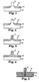
- Figure 1 shows a first construction of a sheet or web 10 having stems 12. This construction uses two layers of coextruded material, an upper layer 14 and a lower layer 16. In this construction, more lower layer material is used. The lower layer 16 forms the base of the sheet, and the core and the upper portion of the stems 12. The upper layer 14 forms a surface layer on the base of the sheet and around the lower portion of the stems. As shown in Figure 1, as well as many of the other embodiments, a single material is used to form the upper and lower layers 14, 16. In alternative embodiments, a plurality of materials and a plurality of sublayers can form the respective upper and lower layers 14, 16.
- Figure 2 shows a construction with more material in the upper layer 14 than in the construction of Figure 1.
- the lower layer 16 again forms the base of the sheet 10 and the core of the stems 12.
- the upper layer 14 forms a crown on a stem made from the lower layer 16.
- the upper layer 14 also forms a surface layer on the base of the sheet, including a sheath of material surrounding the base of the stem.
- the lower layer 16 forms the base of the sheet 10 and a column of core material for the stems 12.
- the upper layer 14 forms the surface layer on the base and on the stems.
- the lower layer 16 again forms the base of the sheet 10 and a small portion of the stems 12.
- the upper layer 14 forms the surface layer on the base and forms the majority of the stem material.
- the lower layer can form any portion of the stems.
- Figure 5 shows a stemmed sheet construction using many layers 18 of material. These many layers could be as few as two layers or scores of different layers. The layers can be two or more different materials that can optionally be repeated in different layers.
- the base of the sheet and the stems both are formed of many layers of material. This construction can result in an end product with only one material (the uppermost layer) forming the surface layer on the base and forming the outer surface of the stems.
- the stems can have many layers exposed along the length of the stem from the bottom of the stem to the top.
- the layers of the stemmed sheet, before stem formation can be formed simultaneously or serially, as long as they are joined together while they are both molten, which may be before either layer has cooled. Thus, the layers are not laminated to each other and are cooled simultaneously. After the stems are formed on one side of the web no further material is added to the other side of the web to complete the web. Optionally, other material, like adhesives and printing can be applied to the web depending on the intended use and application for the web.
- Coextrusion can occur by passing different melt streams from different extruders into a multiple manifold die or a multiple layer teed block and a film die.
- feed block technique at least two different materials are fed from different extruders into different slots (usually 2 to over 200) in a feed block.
- the individual streams are merged in the feed block and enter a die as a layered stack that flows out into layered sheets as the material leaves the die.
- the layered sheet leaving the die is passed between a nip formed by two rolls. At least one of which has a tooled surfaced to create stems.
- the stems can be formed by passing the web through a patterned die lip to form a web having downweb ridges, slicing the ridges and stretching the web to separate the stems.
- the multiple manifold die combines the different molten streams from different extruders at the die lip.
- the layers are then handled as above to form stems. This method is usually limited to 2-3 layered films because of the increased complexity as the number of layers is increased.
- Serial forming can be accomplished by, for example, sequential extrusion, first extruding one layer and then extruding another layer. This can be performed with one or more dies. Alternatively, the layers can be formed in molds or by other known methods. Simultaneous forming can be accomplished by, for example, coextrusion. A single multiple manifold die can be used or a feedblock which splits into multiple cavities to create multiple layers can be used. Alternatively, the layers can be formed in molds or by other known methods.
- the stem density depends on the application for the product. Densities ranging from 12-465 stem/cm 2 (81-3000 stems/in 2 ) are most useful. Many different stem geometries can be used. Stems can be straight, angled, or headed. Headed stems can be shaped like mushrooms, golf tees, or nail heads. They can have an extruded profile. Straight stems can be self mating, can have a pressure-sensitive adhesive (PSA) outer layer, or can be subsequently coated with a PSA.
- PSA pressure-sensitive adhesive
- the stemmed web can also have a smooth surface with a coextruded layer on the smooth side of the web (the side opposite the stems) that combines the mechanical fastening function of the stemmed surface with another function.
- various additives may be used such as physical or chemical blowing agents (to preferentially foam or expand a section of or all of one or more layers) or fillers (to alter material firmness and flow properties).
- foaming agents is to form a cap upon foaming by placing the foaming agent in the material that is in the tip of the stem.
- Microspheres, flame retardants internal release agents, colorants, thermally conductive particles, and electrically conductive particles also can be used.
- Hooks also can be made by capping the stems to form mushroom heads as disclosed in U. S.-A-5,077,870. Also, hooks can be made using profile extrusion, forming a long rib on the web. The rib is then laterally sliced and then stretched to form a plurality of stems. Heads can be formed on the stems either before or after slicing. This is disclosed in U. S.-A-4,894,060.
- stemmed webs of this invention can be used in virtually any application as any other stemmed web.
- Stemmed web samples 1.25 cm wide and 15 cm long were tested for 180° peel adhesion to stainless steel and/or smooth cast biaxially oriented polypropylene films.
- the samples were adhered to the test surfaces by rolling the tapes with a 2.1 kg (4.5 lb) roller using 4 passes.
- One end of a specimen was positioned in a vertical plane with the long dimension extending horizontally with the ends of the specimen gripped between a pair of fixed clamps horizontally spaced 2.5 mm from a pair of movable clamps that grip the other end of the specimen.
- a 20 mm slit was made in the lower edge of the specimen between the two pairs of clamps.
- a pendulum, carrying a circumferentially graduated scale, was then allowed to fall freely, tearing the pre-cut specimen along a continuation of the slit.
- a frictionally mounted pointer on the scale indicated the resistance of the specimen to tearing in grams. This test is commonly referred to as the Elmendorf Tear Strength Test and values are reported in grams/ply.
- a 25.4 mm (1.0 in) wide by approximately 150 mm strip of film was mounted in a tensile testing machine, an Instron TM Tensile Tester, with the upper and lower jaws 25.4 mm apart. The jaws were then separated at the rate of 254 mm/min (10 in/min) until the yield point is reached. The downweb direction of the films was tested after the films were equilibrated at 70-72°C and 50% RH for about 2 weeks. Load at yield was reported in Ib/in width.
- the Tape Snap Test consists of scoring an ink layer with the comer of a single edge razor blade without damaging the underlying print surface, making lines approximately 1 cm apart in a cross-hatched pattern.
- a piece of Scotch TM 610 tape (3M) approximately 10 cm long was applied to the cross-hatched area using a PA1 applicator.(3M), bonding approximately 8 cm of the tape to the ink, leaving one end free to be grabbed by the tester.
- the tape was held by one hand of the tester while the other hand kept the graphic stationary.
- the tape was peeled back at approximately 180° as rapidly as possible by the tester. An excellent result was when no ink was removed by the tape; a good result was when small (5% or less) was removed; a poor result was when significant portions of the ink were removed (5%-25%); a failure was when nearly all the ink was removed.
- the stem-surfaced films of Examples 1-5 all had a PSA layer on the stem surface side of the film and were self-mating fasteners.
- Example 1 Component A (upper layer 14), HL-2542-X (a rubber based PSA in pellet form available from H. B. Fuller), was fed into a single screw extruder having a diameter of about 25mm (1.0 in), an L/D of 24/1, a screw speed of 15.7 rpm and a rising profile up to approximately 182°C.
- Component A was passed through the extruder and continuously discharged at a pressure of at least about 0.69 MPa (100 psi) through a heated neck tube and into one port in a three-layer adjustable vane feed block (Cloeren TM Model 86-120-398, available from Cloeren Co.
- HL-2542-X a rubber based PSA in pellet form available from H. B. Fuller
- Component B (lower layer 16), Shell SRD 7-560 (an ethylene-polypropylene impact copolymer now available from Union Carbide), was fed into a second single screw extruder having a diameter of about 32 mm (1.25 in), an L/D of 24/1, a screw speed of 30 rpm and a temperature profile that steadily increased to approximately 204°C.
- Component B was then continuously discharged at a pressure of at least about 0.69 MPa (100 psi) through a heated neck tube and into a second port in the three-layer feed block.
- the feed block and die were set at approximately 193°C.
- the die gap was 0.5 to 0.8 mm (20 to 30 mils).
- the first roll presented a tooled surface that was heated to 59°C and contained cavities with diameters of about 280 microns (11 mils), depths in excess of about 2.5mm (100 mils) and spacing of about 813 microns (32 mils), resulting in a stem array having a stem density of about 140 stems/cm -2 (900 stems/in 2 ).
- the second roll had a chrome-plated surface that was also heated to 59°C.
- the top side of the two layer molten construction faced the tooled surface and the base side faced the chrome surface.
- the resulting cast film was removed from the tooled surface at a rate of about 1.5 m/min (5 fpm) to form a stem-surfaced film with rod-like stem projections extending from the surface on the film with a diameter of approximately 300 microns and a height of 587 microns.
- These stem structures, resembling Figure 3 were fully covered with the adhesive layer and had a core of Component B.
- the stem-surfaced film was made in a manner similar to that of Example 1 except a tooled surface having a different hole density, a different extruder for Component A, and different process conditions were used.
- the tooled surface had a cavity density that resulted in stem-surfaced films having about 390 stems/cm 2 (2500 stems/in 2 ).
- Component A was fed into a single screw extruder having a diameter of about 32 mm (1.25 in), an L/D of 30/1.
- the screw speeds for the extruders moving Component A and Component B were in a ratio of 12.0/30.0, 7.0/9.3, 7.0/9.3 and 10.0/9.25 for Examples 2-5, respectively, and the maximum temperatures of the extruders feeding Components A and B were 185°C/204°C, 205°C/221°C, 205°C/221°C and 185°C/204°C for Examples 2-5, respectively.
- the web speeds were 2.1 m/min (7 fpm), 2.1 m/min (7 fpm), 3.0 m/min (10 fpm) and 2.1 m/min (7 fpm) for Examples 2 -5, respectively.
- the nip rolls for each example had a pressure of 0.62 MPa (90 psi) and the surfaces of each roll was heated to 65°C, 60°C, 60°C and 48°C for Examples 2-5, respectively.
- the coextruded stem-surfaced films were self-mating and did not require a capped tip and a looped counterpart to mechanically fasten together.
- Adhesion was influenced by Component A thickness as determined by relative screw speeds, used for Component A and Component B, film web speed, and stem-array density.
- the PSA Component A
- the sides of the stems and valleys between the stems were the primary engagement surfaces because the PSA coats both the sides of the stems and the base between the stems.
- the stem-surfaced films of Examples 6-12 were composed of various combinations of at least two different polymers including thermoplastics, thermoplastic elastomers and elastomers.
- Component A acts as a skin layer and Component B acts as a core layer.
- Example 6 The stem-surfaced film of Example 6 was made in a manner similar to that of Example 1 except different materials and process conditions were used.
- Component A was PP7644 (a polypropylene polymer, melt flow 23 g/ 10 sec, available from Amoco) and Component B was PP5A95 (a polypropylene polymer, melt flow 9.5 g/10 sec).
- Component A was passed at 102 rpm through a single screw extruder (32 mm (1.25 in), 24/1 L/D) that was heated to approximately 246°C.
- Component B was passed at 60 rpm through a single screw extruder (19 mm (0.75 in), 38/1 L/D) that was heated to approximately 216°C.
- the feedblock was heated to approximately 246°C.
- the stem-surfaced film traveled at a speed of 1.5 m/min (5 fpm).
- the surface of the roll having the tooled surface was heated to approximately 50°C and the roll having the chrome-plated surface was heated to approximately 50°C.
- the stems on the surface resembled the stem depicted in Figure 3.
- the stems combined the softer feel of softer thermoplastic Component A with the more rigid core support of harder thermoplastic Component B.
- Example 7 the stem-surfaced film was made in a manner similar to that of Example 6 except Component A was PP5A95 and was passed at 45 rpm through a 19 mm (0.75 in) Killion TM single screw extruder with an L/D of 32/1 that was heated to approximately 216°C.
- Component B was ENGAGE TM EG8200 (an ethylene/poly- ⁇ -olefin copolymer available from Dow Plastics Co.) and was passed at 75 rpm through a 32 mm (1.25 in) Killion TM single screw extruder with an L/D of 24/1 that was heated to approximately 232°C.
- the stem-surfaced film traveled at a speed of 2.4 m/min (8 fpm).
- the roll with the tooled surface and the roll with the chrome-plated surface were heated to approximately 70°C.
- the stems on the surface resembled the stem depicted in Figure 1.
- the stem tips had the higher friction of elastic Component B combined the more rigid support of the cylinder formation of the stiffer thermoplastic Component A.
- Example 8 the stem-surfaced film was made in a manner similar to that of Example 7 except Component A was Engage TM EG8200 and was passed at 50 rpm through the extruder and Component B was PP5A95 and was passed at 70 rpm through the extruder.
- the stem-surfaced film traveled at a speed of 2.1 m/min (7 fpm).
- the roll with the tooled surface and the roll with the chrome-plated surface were cooled to approximately 7°C.
- the stems on the surface resembled the stem depicted in Figure 1.
- the stem tips had the lower friction of the stiffer thermoplastic Component A combined the more flexible support of the cylinder formation of the elastomeric Component B.
- Example 9 the stem-surfaced film was made in a manner similar to that of Example 7 except Component A was Engage TM EG8200 and was passed at 60 rpm through the extruder and Component B was Styron TM 666D (a polystyrene, available from Dow Chemical Co.) and was passed at 60 rpm through the extruder.
- the stem-surfaced film traveled at a speed of 2.1 m/min (7 fpm).
- the roll with the tooled surface and the roll with the chrome-plated surface were heated to approximately 7°C.
- the stems on the surface resembled the stem depicted in Figure 3.
- the stems combined the smooth feel of elastomeric Component A with the rigid core support of a hard thermoplastic Component B.
- Example 10 the stem-surfaced film was made in a manner similar to that of Example 7 except Component A was passed at 60 rpm through the extruder and Component B was a preblended mixture of 20 wt percent Styron TM 666D and 80 wt percent PP5A95, and was passed at 50 rpm through the extruder.
- the stem-surfaced film traveled at a speed of 3.0 m/min (10 fpm).
- the roll with the tooled surface and the roll with the chrome-plated surface were heated to approximately 50°C.
- the stems on the surface resembled the stem depicted in Figure 3.
- the stems combined the softer feel of less rigid thermoplastic Component A with the reinforcement supplied by a core having elongated discontinuous regions of a more rigid thermoplastic in a continuous region of the same material as the skin.
- Example 11 the stem-surfaced film was made in a manner similar to that of Example 7 except Component A was No. 1057 (a polypropylene homopolymer, melt flow index of 11 g/10 sec, available from Union Carbide) and was passed at 15 rpm through a 38 mm (1.5 in) Davis Standard Model DS 15S single screw extruder having an L/D of 24:1 and a temperature profile rising from approximately 190°C to 232°C.
- Component A was No. 1057 (a polypropylene homopolymer, melt flow index of 11 g/10 sec, available from Union Carbide) and was passed at 15 rpm through a 38 mm (1.5 in) Davis Standard Model DS 15S single screw extruder having an L/D of 24:1 and a temperature profile rising from approximately 190°C to 232°C.
- Component B was a preblended mixture of Carbide TM 5A97 (a polypropylene homopolymer, melt flow index of 5 g/10 sec, available from Union Carbide) and Vector TM 4111 ( a styrene isoprene block copolymer, available from Dexco Polymers).
- the mixture was made in a weight ratio of 40:60 and was passed at 15 rpm through a 64 mm (2.5 in) Davis Standard Model 25IN25 single screw extruder having an L/D of 24:1 and a temperature profile rising from approximately 204°C to 232°C.
- the 3-layer Cloeren TM feedblock was a Model J.O.
- a stem-surfaced film was made from only a single layer of SRD 7-560 having similar thickness and stem-array density as that of Example 11.
- Example 12 the stem-surfaced film was made in a manner similar to that of Example 11 except Component A was Attane TM 4802 (an ultra low density polyethylene available from Dow Chemical Co.) and was passed at 48 rpm through the extruder and Component B was SRD 7-560 and was passed at 122 rpm through the extruder. Component A was directed to the outer two layers of the feedblock and Component B was directed to the middle layer. The relative feed rates of Component A and Component B resulted in a film having an ABA construction where the ratio by weight of ABA was 10:80:10. The stem-surfaced film traveled at a speed of 18.3 m/min (60 fpm).
- the roll with the tooled surface and the roll with the chrome-plated surface were heated to approximately 71°C.
- the stems on the surface resembled the stem depicted in Figure 3.
- the low molecular weight thermoplastic Component B provided a less rigid stem core that caused the stems to feel softer.
- the shell of Component A made the stems suitably rigid.
- the large excess of Component B provided a more flexible base film that allowed the stem-surfaced film to be significantly less rigid than Comparative Example 1.
- the properties of the heads, the stems and the base films can vary over a wide range depending on both the type of polymer components used as a skin or a core material and the configuration of the polymers in the shafts, the heads of the capped stems, and in the base film. Also, multiple layered stems were observed to fill the tooled surface more completely than homogeneous stems (Example 12 vs. Comparative Example 1).
- a three layer stem-surfaced film was made with a discontinuous middle layer.
- the film was made in a manner similar to that used in Example 12 except different materials and process conditions were used.
- Component A was SRD 7-560 and was passed at 50.1 and 41.3 rpm through two 64 mm (2.5 in) single screw extruders each having an L/D of 24:1 and a temperature profile rising from approximately 218°C to 274°C and into the outer two layers of a 3-layer Cloeren TM Model adjustable vane feedblock.
- Component B Kraton TM G1657 (a linear styrene-(ethylene-butylene) block copolymer, available from Shell Chemical Co.), was fed at 45 rpm through a 38 mm (1.5 in) single screw extruders having an L/D of 24:1 and a temperature profile rising from approximately 160°C to 204°C and into the middle layer of the feedblock.
- a steel insert was bolted to the lower vane and the upper vane was moved into contact with the insert to constrict the flow of the Component B into 6 mm (1/4 in) wide slots that were machined onto the insert at 83 mm (3-1/4 in) intervals.
- Component B exited from the insert channels and was encapsulated by the upper and lower layers of Component A just before entering the land area of a 45 7 mm (18 in) Cloeren TM die.
- the roll with the tooled surface and the roll with the chrome-plated surface were maintained at approximately 26°C and 6°C, respectively.
- the stem-surfaced film traveled at a speed of 15.2 m/min (50 fpm) and had a stem height of about 760 microns (30 mils), a stem density of about 140 stems/cm 2 (900 stems/in 2 ), and an overall weight of about 170 g/m 2 .
- the stem surface film was then passed over a roll heated to about 137°C to cause the tips of the stems to soften and form mushroom shaped heads or caps.
- the film was pulled in the transverse direction the film exhibited elastic stretch properties in the region where the discontinuous Component B was embedded.
- the stem-surfaced films of Examples 14 and 15 were composed of two different polymers, Component A and Component B, arranged in alternating layers, i.e., ABA...BA, as shown in Figure 6.
- Example 14 the stem-surfaced film was made in a manner similar to Example 6 except that different materials were used and a different processing conditions were used that included a multilayer arrangement that resulted in a polymeric web having 29 layers.
- Component A was Carbide TM 7-587 (a propylene copolymer, available from Union Carbide), and was passed at 122 rpm through a 64 mm (2.5 in) Davis Standard Model 25IN25 single screw extruder having an L/D of 24:1 and a temperature profile rising from approximately 204°C to 232°C.
- Component B was Exact TM 4041 (an ethylene-butene copolymer polyolefin, available from Exxon) and was passed at 48 rpm through a 38 mm (1.5 in) Davis Standard Model DS 15 S single screw extruder having an L/D of 24:1 and a temperature profile rising from approximately 190°C to 232°C. The two molten materials were then supplied to predetermined slot locations in a 70 mm (97.5 in) Extrusion Die Model No. 71, available from Johnson Plastic Machinery.
- the feedblock contained an insert having a linear array of adjacent slots each having an X (width) dimension of 12.5 mm for all layers (i.e., interior and exterior) of Component A. All other slots had an X dimension of 9.4 mm.
- Transfer tubes connected each extruder to first and second distribution manifolds which delivered the materials to the predetermined slot locations in the insert. There were 29 slots, 15 for Component A and 14 for Component B.
- the product exiting the insert had a generally rectangular cross section and had alternating layers of Component A and Component B. After exiting the insert the product was comparatively smoothly compressed along its Y axis (height) while being comparatively smoothly expanded along its X axis (width).
- the now wide and relatively thin film was passed through the adjustable lips of the die to obtain a flat film.
- the feed rates were adjusted to yield a film having a ratio by weight of Component A to Component B of 80:20.
- the film traveled at a speed of 16.5 m/min (54 fpm).
- the roll having the tooled surface and the toll having the chrome-plated surface were heated to approximately 71°C and 93°C, respectively.
- Example 15 The stem-surfaced film of Example 15 was made in a manner similar to that of Example 14, except 121 slots were used resulting in a film having 61 alternating layers of Component A and 60 alternating layers of Component B and the film speed was 12.2 m/min (40 fpm).
- a stem-surfaced film was made from only a single layer of Carbide TM 7-587 having similar thickness and stem-array density as that of Example 14.
- Example Load at Yield (kg/cm width) Tear (grams/ply) Impact Full (cm-kg) Creased (cm-kg) CE2 1.4 22 6.6 0.3 14 1.3 40 11.3 2.8 15 1.9 63 11.7 3.7
- Example 16 demonstrates the applicability of the present invention to prepare a stem-surfaced sheet that readily accepts printing or other indicia.
- a bicomponent stem-surfaced film was made of polypropylene (Shell "SRD 7-560") and Bynel TM 3101 copolymer (an acrylate-modified ethylene-vinyl acetate copolymer, available from E. I. DuPont de Nemours, Wilmington,, Delaware).
- the polypropylene was extruded at about 55 rpm from a 3 8 mm single-screw extruder (Johnson Company) having an L/D of 30:1 and a temperature profile rising from approximately 150°C to 205°C.
- the copolymer was extruded at about 20 rpm from a 25 mm Killion single-screw extruder (Killion Company, Ann Arbor, Michigan) having an L/D of 30:1 and a temperature profile rising from about 150°C to about 205°C.
- the two extrudates were combined in a 203-mm wide split-manifold film die (Extrusion Dies, Incorporated, Chippewa Falls, Wisconsin).
- the exuding bicomponent film was directed into the nip between the top and middle rolls of a 3-roll stack having provision for cooling and rotating at 2.68 m/min (8.8 ft/min).
- the top and bottom rolls were made of chrome-plated steel, and the middle roll was covered with rubber, the rubber having a uniform array of 0.508 mm (0.020 in) diameter by 2.03 mm (0.080 in) deep holes in its surface.
- the array of holes was disposed in equally-spaced, staggered rows parallel to the axis of rotation of the roll. The spacing between holes in each row was 2.79 mm (0.110 in) and the rows were spaced 1.40 mm (0.055 in) apart.
- the resultant stemmed-surface bicomponent film was directed to a winder.
- the resultant film had stem side of polypropylene and a smooth side consisting of a 25 to 50 mm thick layer of Bynel copolymer.
- a stem-surfaced film made of Shell polypropylene SRD7-560 having stem dimensions and a stem array density similar to Comparative Example 2 (except the film speed was 12.2 m/min (40 fpm)) was subsequently processed to cap the stems,
- the stem-surfaced film was then coated with a layer of Bynel TM 3101 having a thickness of 25 microns using a 44 mm (1.35 in) Prodex Model 13524 single screw extruder having an L/D of 14:1 and a temperature profile rising to approximately 227°C and a single layer die having a width of about 305 mm (12 in).
- the web was moving at a speed of 9.1 m/min (20 ft/min).
- the extrusion coating occurred at a heated nip where a chrome roll was heated to 121°C and a rubber backup roll that touched the stem surface was heated to 10°C to maximize the interfacial bond without distorting the capped stem structures.
- Example 16 and Comparative Example 3 were subsequently corona treated and coated with SSKP-4000 Black Flexographic Ink (available from Werneke Inks, Plymouth, Minnesota) using a Pamarco Hand Proofer (available from Pamarco Inc., Roselle, New Jersey). The ink was allowed to dry at ambient conditions for ten minutes. A good print quality was obtained for each sample and a Tape Snap Test was performed on each. For Example 16, good ink adhesion was demonstrated and no delamination of Component B from Component A was observed. For Comparative Example 3, good ink adhesion was demonstrated but some delamination was observed between Component B and Component A.
- a stem surface material similar to Example 16 was coextruded in a different manner.
- a single layer Cloeren die approximately 70 cm wide was fed with material from a Cloeren 3 layer feedblock that was set up for only two layers.
- Component A was blended to 96% Union Carbide SRD 7-587 and 4% Reed Spectrum Pigment Concentrate (11000409224), which was passed at 15.9 rpm through a 64 mm Davis Standard single screw extruder having a L/D ratio of 24:1 and a temperature profile rising from 215°C to 260°C.
- Component B- was a blend of 96% Bynel 3101 and 4% Reed Spectrum Pigment Concentrate, which was passed at 27 rpm through a 38 mm Davis Standard single screw extruder having an L/D ratio of 24:1, and a temperature profile rising from approximately 150°C to 205°C.
- the relative feed rates were adjusted such that the film thickness of Component A is approximately 130 to 150 microns, plus the height of the pins, and Component B is approximately 25 to 50 microns thick.
- the stem surface film traveled at a speed of 16.8 m/min.
- the roll with various tooled surfaces was heated to approximately 52°C and the chrome plated rolls were heated to approximately 15°C.
- the average nip pressures were both 23 psi.
- a finished web width of 50 cm was obtained after edge trimming.
- Product was made at pin densities of 50 pins/cm 2 and 140 pins/cm 2 .
- the stem web was then passed at 12 m/min through two heated nips where the hot roll facing the stem surface was heated to approximately 140°C and a cold chrome roll facing the B layer was chilled to approximately 7°C. Mushroom-shaped caps were formed on the stems while the component B layer was left undisturbed.
- the B layer was air corona treated to improve the ink receptivity of the B layer.
- a first sample with a pin density of 140 pins/cm 2 was printed by the Scotchprint TM Electrostatic process.
- Printed transfer paper 8603 was heat laminated to the smooth B layer using an Orca III laminator with a top roll temperature of 92°C and a bottom roll temperature of 56°C, with 50 psi pressure and a laminating speed of 0.76 m/min. Complete transfer of the image was obtained. Visual examination showed that a defect-free transfer was obtained with good color density.
- a second sample having pin densities of 50 pins/cm 2 and 140 pins/cm 2 were printed with Scotchcal 9705 black screen printing ink using a 390T screen and cured with a medium pressure mercury vapor focused UV lamps at 168 mJ/cm 2 (American Ultraviolet Co., Murrary Hill, NJ).
- the printed samples were tested for ink adhesion using the Tape Snap Test. Excellent ink adhesion was obtained for both lots.
- Lot 9701-3 as prepared in Example 17 had an Ink Jet Receptor coating (3M 8502URC) heat laminated to the smooth side of the 9701-3 material on a 3M 9540 laminator at 82°C, 0.3 meters/min and at 64 psi.
- the subsequent construction was then fed through a Novajet III inkjet printer (Encad Inc. 6059 Cornerstone Ct. W., San Diego, California), with American Inkjet Inks (American Inkjet, 13 Alexander Rd, Billeria, Massachusetts). Testing with the Tape Snap Test indicated good ink anchorage with no ink being removed from the surface of the web.
- a stem surface the same as Comparative Example 3 was corona treated in the same manner.
- An ink jet receptor coating was laminated to the smooth surface and the coating was printed in the same manner as Example 18. Testing with the Tape Snap Test resulted in complete removal of the ink and the ink jet receptor coating from the surface of the web.
- the stem-surfaced films of Example 19 was composed of two different polymers, Component A and Component B, arranged in a two layer configuration, where each side of the film had a stem array protruding from the surface.
- the stem-surfaced film of Example 19 demonstrated the efficacy of the present invention to make an industrial roll covering material having projections on both major surfaces, each being of a different composition.
- Such articles provide an improved friction surface with an integral attachment system.
- a molten bicomponent polymeric film having two major surfaces was prepared by extruding material through a split-manifold bicomponent film die fed by two single-screw extruders, both operating at 204°C.
- the first major surface of the bicomponent film was of Component A, Shell polypropylene SRD 7-560, now available from Union Carbide Corporation, Danbury, CT.
- the second major surface was of Component B, Rexflex TM FP-D1720 flexiblized polypropylene, commercially available from Rexene Corporation, Dallas, Texas.
- the extruded bicomponent film was introduced into the nip between the top and middle roll of a vertical stack of three temperature-controlled co-rotating 5-in diameter (12.70 cm) cylindrical rolls aluminum sleeves.
- the middle and top rolls have aluminum sleeves with cylindrical cavities (0.66 mm (0.026 in) deep by 0.46 mm (0.018 in) in diameter, and 1.32 mm (0.052 in) deep by 0.46 mm (0.018 in) in diameter, respectively) disposed in rows parallel to the rotational axis about the circumference of each roll, the cavities and rows both being spaced 1.41 mm (0.0556 in) apart. Alternate rows of cavities were offset 0.71 mm (0.0278 in) to produce a staggered array.
- the continuous, molten bicomponent film was deposited into the nip between the top and middle rolls, the roll was rotated approximately 180° to the nip between the middle and bottom rolls where the now partially-cooled bicomponent film was contacted by and transferred to the surface of the third roll, which is a chrome plated steel roll, and the third roll rotated another 180° where the molded bicomponent article was removed from the second roll surface by a tension-controlled winder.
- the stems formed on the first major surface were readily deformable into a mushroom-shaped cap upon contact with a hot surface to provide a mechanical fastening surface suitable for mating with a surface having a fibrous loop surface or to itself.
- the projections thus formed on the second major surface were tough and flexible, providing controlled friction when engaging a traversing web or sheet when employed as the contact surface of an industrial roll.
- the stem-surfaced film of Example 20 was composed of two different polymers, Component A and Component B, arranged in a three layer ABA configuration having stems depicted in Figure 1 where the middle layer composed of Component B is elastic and is able to relieve stress that may otherwise occur in subsequent processing operations. This film was made using extrusion.
- Component A SRD 7-560
- Component B Exact TM ULDPE, a linear low density polyethylene available from Exxon
- Component A was then passed into the top and bottom of an 46 mm (18 in) wide three layer die and Component B was passed into the middle to form a molten three-layer film.
- the molten three-layer film was fed into a nip formed by two rolls having a tooled surface side and a smooth surface side and pressed with a force of up to 0.41 MPa (60 psi).
- the tooled surface contained cavities with a diameter of about 430 microns (17 mils), depths in excess of about 1.52 mm (60 mils) and spacing such as to result in a stem array having a stem density of about 50 stems/cm 2 (324 stems/in 2 ).
- the two surfaces had a temperature maintained at about 90°C.
- the resulting cast film was removed from the tooled surface at a rate of about 16.5 m/min (55 fpm) to form a stem-surfaced film that resembled Figure 4.
- the film had a base thickness of about 127 microns (5 mils) with rod-like stem projections extending from the surface on the film having a diameter of approximately 430 microns and a stem height of about 760 microns (30 mils).
- the 127 micron base film consisted of three layers, two outer layers of Component A having a thickness of about 51 microns (2 mils) and a middle layer of Component B having a thickness of about 25 microns (1 mil).
- the stem-surface film was then run at 7.6 m/min (25 fpm) with the stem-surface on top through a three-roll, two-nip heated stack to form caps on the end of the stems having diameters of 760 microns (30 mils) and heights of about 510 microns (20 mils).
- the two outside rolls were heated to about 149°C, the middle roll to about 16°C and the gaps of both nips were between 380-635 microns (15-25 mils).
- the three-layer stem-surface film with capped stems was used as the backing in a coated abrasive article, which was produced in a manner similar to the teachings of U.S.-A-5,551.961.
- the abrasive mineral used was a grade 180 heat treated aluminum oxide, and both the make and size coats were a blend of phenolic and ureaformaldehyde binders
Landscapes
- Engineering & Computer Science (AREA)
- Mechanical Engineering (AREA)
- Manufacturing & Machinery (AREA)
- Laminated Bodies (AREA)
- Extrusion Moulding Of Plastics Or The Like (AREA)
- Slide Fasteners, Snap Fasteners, And Hook Fasteners (AREA)
- Materials For Medical Uses (AREA)
Applications Claiming Priority (3)
| Application Number | Priority Date | Filing Date | Title |
|---|---|---|---|
| US08/943,482 US6106922A (en) | 1997-10-03 | 1997-10-03 | Coextruded mechanical fastener constructions |
| US943482 | 1997-10-03 | ||
| PCT/US1998/020634 WO1999017630A1 (en) | 1997-10-03 | 1998-09-29 | Coextruded mechanical fastener constructions |
Publications (2)
| Publication Number | Publication Date |
|---|---|
| EP1028639A1 EP1028639A1 (en) | 2000-08-23 |
| EP1028639B1 true EP1028639B1 (en) | 2004-06-16 |
Family
ID=25479742
Family Applications (2)
| Application Number | Title | Priority Date | Filing Date |
|---|---|---|---|
| EP98950834A Expired - Lifetime EP1028639B1 (en) | 1997-10-03 | 1998-09-29 | Coextruded mechanical fastener constructions |
| EP98950900A Expired - Lifetime EP1018906B1 (en) | 1997-10-03 | 1998-10-02 | Elastic fastener |
Family Applications After (1)
| Application Number | Title | Priority Date | Filing Date |
|---|---|---|---|
| EP98950900A Expired - Lifetime EP1018906B1 (en) | 1997-10-03 | 1998-10-02 | Elastic fastener |
Country Status (11)
| Country | Link |
|---|---|
| US (3) | US6106922A (enExample) |
| EP (2) | EP1028639B1 (enExample) |
| JP (4) | JP4535612B2 (enExample) |
| KR (2) | KR100512830B1 (enExample) |
| CN (2) | CN1222234C (enExample) |
| AU (2) | AU732065B2 (enExample) |
| BR (2) | BR9812603A (enExample) |
| DE (2) | DE69824621T2 (enExample) |
| ES (1) | ES2262246T3 (enExample) |
| IL (2) | IL135104A0 (enExample) |
| WO (2) | WO1999017630A1 (enExample) |
Cited By (1)
| Publication number | Priority date | Publication date | Assignee | Title |
|---|---|---|---|---|
| EP2123826A2 (de) | 2008-05-21 | 2009-11-25 | Gottlieb Binder GmbH & Co. KG | Verfahren und Vorrichtung zum Herstellen eines Flächenproduktes sowie das Flächenprodukt selbst |
Families Citing this family (150)
| Publication number | Priority date | Publication date | Assignee | Title |
|---|---|---|---|---|
| US6930277B2 (en) * | 1997-09-10 | 2005-08-16 | Velcro Industries B.V. | Fastener element molding |
| US6035498A (en) * | 1997-01-27 | 2000-03-14 | Velcro Industties B.V. | Stretched fasteners |
| US6106922A (en) * | 1997-10-03 | 2000-08-22 | 3M Innovative Company | Coextruded mechanical fastener constructions |
| AUPP591998A0 (en) | 1998-09-15 | 1998-10-08 | Anthony Smith Australasia Pty Ltd | Closure |
| WO2000020200A1 (en) * | 1998-10-02 | 2000-04-13 | 3M Innovative Properties Company | Laminated elastic composites |
| US20120027990A1 (en) * | 1998-10-05 | 2012-02-02 | 3M Innovative Properties Company | Article for wet applications |
| US6610382B1 (en) * | 1998-10-05 | 2003-08-26 | 3M Innovative Properties Company | Friction control article for wet and dry applications |
| US7309519B2 (en) * | 1998-10-05 | 2007-12-18 | 3M Innovative Properties Company | Friction control articles for healthcare applications |
| US8277922B2 (en) * | 1998-10-05 | 2012-10-02 | 3M Innovative Properties Company | Stem web |
| US6205623B1 (en) | 1998-11-06 | 2001-03-27 | Velcro Industries B.V. | Composite hook and loop fasteners, and products containing them |
| US7048818B2 (en) | 2000-03-14 | 2006-05-23 | Velcro Industries B.V. | Hook and loop fastening |
| CN1108233C (zh) * | 1999-02-25 | 2003-05-14 | 3M创新有限公司 | 具有离散的柱杆区的卷材 |
| US7018496B1 (en) | 1999-04-26 | 2006-03-28 | 3M Innovative Properties Company | Curable mechanical fasteners |
| DE60004228T2 (de) | 1999-06-01 | 2004-04-22 | 3M Innovative Properties Co., St. Paul | Optisch transparente mikrogeprägte empfangsmedien |
| WO2000073082A1 (en) | 1999-06-01 | 2000-12-07 | 3M Innovative Properties Company | Random microembossed receptor media |
| AU5813200A (en) | 1999-06-18 | 2001-01-09 | Henkel Kommanditgesellschaft Auf Aktien | Use of a film with anchoring elements for a mechanic fixation |
| MXPA02002359A (es) * | 1999-09-04 | 2002-07-30 | Solutia Inc | Felpas multicolor, aparato y metodo. |
| US6588074B2 (en) | 2000-02-10 | 2003-07-08 | 3M Innovative Properties Company | Self-mating reclosable binding strap and fastener |
| DE60123390T2 (de) | 2000-02-10 | 2007-08-02 | 3M Innovative Properties Co., Saint Paul | Wiederverschliessbarer bündelungsriemen mit klettverschluss |
| US6367128B1 (en) | 2000-02-10 | 2002-04-09 | 3M Innovative Properties Company | Self-mating reclosable mechanical fastener |
| AU2001245717A1 (en) | 2000-03-14 | 2001-09-24 | Velcro Industries B.V. | Folded fastener products |
| AU2001243602A1 (en) | 2000-03-14 | 2001-09-24 | Velcro Industries B.V. | Stretchable fastener |
| US7162780B2 (en) * | 2001-02-26 | 2007-01-16 | Velcro Industries B.V. | Skin-friendly hook fastening component |
| US6484371B1 (en) | 2001-02-27 | 2002-11-26 | 3M Innovative Properties Company | High strength, flexible, light weight hook and loop bundling straps |
| US6516943B2 (en) | 2001-04-12 | 2003-02-11 | 3M Innovative Properties Company | Conveyor belt splice cover, and methods |
| DE10123205A1 (de) * | 2001-05-12 | 2002-11-28 | Binder Gottlieb Gmbh & Co | Verfahren zur Herstellung eines Haftverschlußteils |
| DE10123206A1 (de) * | 2001-05-12 | 2002-11-28 | Binder Gottlieb Gmbh & Co | Verfahren zum Herstellen eines Haftverschlußteils |
| US6763556B2 (en) * | 2001-09-18 | 2004-07-20 | 3M Innovative Properties Company | Mating film and method for bundling and wrapping |
| US7001475B2 (en) | 2001-12-11 | 2006-02-21 | 3M Innovative Properties Company | Film structures and methods of making film structures |
| US6949283B2 (en) * | 2001-12-19 | 2005-09-27 | 3M Innovative Properties Company | Polymeric coextruded multilayer articles |
| US6846232B2 (en) * | 2001-12-28 | 2005-01-25 | 3M Innovative Properties Company | Backing and abrasive product made with the backing and method of making and using the backing and abrasive product |
| JP2003204809A (ja) * | 2002-01-10 | 2003-07-22 | Three M Innovative Properties Co | 面ファスナー |
| US7497623B2 (en) * | 2002-02-27 | 2009-03-03 | Pactiv Corporation | Packages with active agents |
| US20060291756A1 (en) * | 2002-02-27 | 2006-12-28 | Thomas Toby R | Web materials with active agent for use in forming reclosable packages |
| JP2003300636A (ja) * | 2002-04-08 | 2003-10-21 | Three M Innovative Properties Co | シート送り装置、シート分離部材、シート送り組立体及びシート分離組立体 |
| US6686026B2 (en) | 2002-04-08 | 2004-02-03 | 3M Innovative Properties Company | Micro-channeled protective film |
| JP2004011734A (ja) * | 2002-06-06 | 2004-01-15 | Three M Innovative Properties Co | 弾性部材及びそれを使用した給紙ローラ |
| US6755878B2 (en) | 2002-08-02 | 2004-06-29 | 3M Innovative Properties Company | Abrasive articles and methods of making and using the same |
| US6684464B1 (en) | 2002-08-07 | 2004-02-03 | 3M Innovative Properties Company | Bundling strap |
| WO2004058122A1 (en) * | 2002-12-16 | 2004-07-15 | Velcro Industries B.V. | Medical wraps |
| US6919504B2 (en) * | 2002-12-19 | 2005-07-19 | 3M Innovative Properties Company | Flexible heat sink |
| US6957884B2 (en) * | 2002-12-27 | 2005-10-25 | Kinberly-Clark Worldwide, Inc. | High-speed inkjet printing for vibrant and crockfast graphics on web materials or end-products |
| US7155746B2 (en) * | 2002-12-27 | 2007-01-02 | Kimberly-Clark Worldwide, Inc. | Anti-wicking protective workwear and methods of making and using same |
| US6934969B2 (en) * | 2002-12-27 | 2005-08-30 | Kimberly-Clark Worldwide, Inc. | Anti-wicking protective workwear and methods of making and using same |
| US7943813B2 (en) | 2002-12-30 | 2011-05-17 | Kimberly-Clark Worldwide, Inc. | Absorbent products with enhanced rewet, intake, and stain masking performance |
| US20040170342A1 (en) * | 2003-02-28 | 2004-09-02 | 3M Innovative Properties Company | Slidable fastener bearing assembly |
| USD505063S1 (en) | 2003-03-21 | 2005-05-17 | 3M Innovative Properties Company | Bundling strap |
| USD496854S1 (en) | 2003-03-21 | 2004-10-05 | 3M Innovative Properties Company | Bundling strap |
| USD500671S1 (en) | 2003-03-21 | 2005-01-11 | 3M Innovative Properties Company | Self-engaging bundling strap provided with machine readable code |
| USD511450S1 (en) | 2003-03-21 | 2005-11-15 | 3M Innovative Properties Company | Self-engaging bundling strap provided with machine readable code |
| USD505064S1 (en) | 2003-03-21 | 2005-05-17 | 3M Innovative Properties Company | Bundling strap |
| US7883769B2 (en) * | 2003-06-18 | 2011-02-08 | 3M Innovative Properties Company | Integrally foamed microstructured article |
| IL156789A0 (en) * | 2003-07-06 | 2004-02-08 | Adapter for multi-element contact-probe | |
| US8273066B2 (en) | 2003-07-18 | 2012-09-25 | Kimberly-Clark Worldwide, Inc. | Absorbent article with high quality ink jet image produced at line speed |
| DE10334675A1 (de) * | 2003-07-30 | 2005-02-24 | Gottlieb Binder Gmbh & Co. Kg | Verfahren zum Einfärben und/oder Bedrucken |
| DE50301884D1 (de) * | 2003-08-21 | 2006-01-12 | Heimbach Gmbh & Co | Träger als oder für eine Papiermaschinenbespannung |
| US7172008B2 (en) * | 2003-09-18 | 2007-02-06 | Velcro Industries B.V. | Hook fasteners and methods of making the same |
| US20050136214A1 (en) * | 2003-12-18 | 2005-06-23 | 3M Innovative Properties Company | Mounting board |
| US20050217087A1 (en) * | 2004-04-05 | 2005-10-06 | Gallant Christopher M | Self-engaging, double-sided fastener products |
| US20050276945A1 (en) * | 2004-06-09 | 2005-12-15 | Muggli Mark W | Composite articles and methods of making the same |
| US20050276985A1 (en) * | 2004-06-09 | 2005-12-15 | Muggli Mark W | Composite article having a tie layer and method of making the same |
| US20050276944A1 (en) * | 2004-06-09 | 2005-12-15 | Muggli Mark M | Composite articles and methods of making the same |
| US7416776B2 (en) * | 2004-09-02 | 2008-08-26 | 3M Innovative Properties Company | Substrates with multiple images |
| US7446940B2 (en) * | 2004-09-02 | 2008-11-04 | 3M Innovative Properties Company | Substrates with multiple images and methods of use |
| US20060046159A1 (en) * | 2004-09-02 | 2006-03-02 | Emslander Jeffrey O | Methods of manufacturing substrates with multiple images |
| US7404997B2 (en) * | 2004-09-02 | 2008-07-29 | 3M Innovative Properties Company | Substrates with multiple images |
| US8114502B2 (en) * | 2004-09-02 | 2012-02-14 | 3M Innovative Properties Company | Substrates with multiple images |
| FR2876141B1 (fr) * | 2004-10-06 | 2006-12-08 | Sandvik Tamrock Secoma Sas Soc | Dispositif de foration par rotopercussion |
| DE102004062042A1 (de) * | 2004-12-23 | 2006-07-06 | Gottlieb Binder Gmbh & Co. Kg | Verfahren zum Einfärben einer Trägerbahn |
| KR20070116878A (ko) | 2005-03-11 | 2007-12-11 | 쓰리엠 이노베이티브 프로퍼티즈 캄파니 | 패스너의 제조 방법 |
| EP1702599A1 (en) * | 2005-03-18 | 2006-09-20 | 3M Innovative Properties Company | Absorbent article |
| EP1885210A1 (en) * | 2005-03-23 | 2008-02-13 | Velcro Industries B.V. | Molding touch fastener elements |
| US20060226205A1 (en) | 2005-04-06 | 2006-10-12 | 3M Innovative Properties Company | Management article with retractable hangars |
| US20060225322A1 (en) | 2005-04-06 | 2006-10-12 | 3M Innovative Properties Company | Repositionable indexing tab device |
| US7601284B2 (en) * | 2005-04-06 | 2009-10-13 | Velcro Industries B.V. | Molding fastener elements on folded substrate |
| US20060251890A1 (en) * | 2005-05-06 | 2006-11-09 | Richard Lane | Pressure sensitive adhesive (PSA) laminates |
| US20060263596A1 (en) * | 2005-05-06 | 2006-11-23 | Bamborough Derek W | Pressure sensitive adhesives (PSA) laminates |
| US20060251889A1 (en) * | 2005-05-06 | 2006-11-09 | Richard Lane | Pressure sensitive adhesive (PSA) laminates |
| US20060251888A1 (en) * | 2005-05-06 | 2006-11-09 | Richard Lane | Pressure sensitive adhesive (PSA) laminates |
| US7594976B2 (en) * | 2005-05-13 | 2009-09-29 | 3M Innovative Properties Company | Methods of manufacturing substrates |
| JP4841190B2 (ja) * | 2005-07-27 | 2011-12-21 | Ykk株式会社 | 玉縁芯材 |
| US7467873B2 (en) | 2005-10-14 | 2008-12-23 | 3M Innovative Properties Company | Privacy film |
| US7326504B2 (en) | 2005-10-14 | 2008-02-05 | 3M Innovative Properties Company | Imaged anti-copy film |
| US8034431B2 (en) * | 2006-01-25 | 2011-10-11 | 3M Innovative Properties Company | Intermittently bonded fibrous web laminate |
| DE102006022971A1 (de) * | 2006-05-11 | 2007-11-15 | Karl Otto Braun Gmbh & Co. Kg | Medizinisches Flächengebilde |
| US7636988B2 (en) * | 2006-09-11 | 2009-12-29 | 3M Innovative Properties Company | Methods for making fasteners |
| US20080134476A1 (en) * | 2006-12-11 | 2008-06-12 | Steindorf Eric C | Fastener having adjustable fastening strength |
| US20090032059A1 (en) * | 2007-08-03 | 2009-02-05 | 3M Innovative Properties Company | Cleaning material and method of cleaning a surface |
| US8551377B2 (en) * | 2007-09-11 | 2013-10-08 | Velcro Industries B.V. | Forming touch fasteners on substrates |
| US20100192321A1 (en) * | 2009-01-30 | 2010-08-05 | 3M Innovative Properties Company | Hair and lint cleaning tool |
| WO2010099148A1 (en) * | 2009-02-27 | 2010-09-02 | 3M Innovative Properties Company | Method and apparatus for cross-web coextrusion and film therefrom |
| US20100219555A1 (en) * | 2009-02-27 | 2010-09-02 | Tyco Electronics Corporation | Method for extrusion of multi-layer coated elongate member |
| JP5718926B2 (ja) | 2009-09-24 | 2015-05-13 | スリーエム イノベイティブ プロパティズ カンパニー | ウェブ搬送装置用ローラ係合カバーの作製方法 |
| WO2011097436A1 (en) | 2010-02-08 | 2011-08-11 | 3M Innovative Properties Company | Method of co-extruding, co-extrusion die, and extruded articles made therefrom |
| BR112012021531A2 (pt) | 2010-02-26 | 2017-06-27 | 3M Innovative Proferties Company | sistemas de suporte de paciente e métodos para transferência de pacientes e controle de temperatura de pacientes. |
| KR101753933B1 (ko) | 2010-03-30 | 2017-07-19 | 쓰리엠 이노베이티브 프로퍼티즈 컴파니 | 프로파일화된 압출 복제 |
| US9138957B2 (en) | 2010-06-21 | 2015-09-22 | 3M Innovative Properties Company | Slit hook strips and laminates and articles containing the same |
| USD667043S1 (en) | 2010-09-17 | 2012-09-11 | Couch Iii Quest C | Extendable strap |
| US8465824B2 (en) | 2010-09-17 | 2013-06-18 | Quest C. Couch, III | Strap for securing accessories to photographic flash units |
| US8973225B2 (en) | 2010-12-21 | 2015-03-10 | 3M Innovative Properties Company | Structured surface with multiple-post caps and method of making the same |
| US8845943B2 (en) | 2010-12-21 | 2014-09-30 | 3M Innovative Properties Company | Method of making a structured surface and article therefrom |
| US9138031B2 (en) | 2011-02-16 | 2015-09-22 | 3M Innovative Properties Company | Method of making a mechanical fastening strip and reticulated mechanical fastening strip therefrom |
| EP2545798B1 (en) | 2011-07-13 | 2018-02-21 | 3M Innovative Properties Company | Sanitary product system |
| KR102197781B1 (ko) | 2011-09-16 | 2021-01-04 | 쓰리엠 이노베이티브 프로퍼티즈 캄파니 | 기계식 체결구, 체결 시스템, 및 일회용 흡수 용품 |
| US9358714B2 (en) | 2011-12-13 | 2016-06-07 | 3M Innovative Properties Company | Structured film containing beta-nucleating agent and method of making the same |
| US9278471B2 (en) | 2011-12-13 | 2016-03-08 | 3M Innovative Properties Company | Method of detecting a component of an article and method of preparing a component for detection |
| MX373211B (es) | 2011-12-13 | 2020-04-23 | 3M Innovative Properties Company | Pelicula estructurada que contiene agente beta-nucleante y metodo para elaborar la misma. |
| EP2849602B1 (en) | 2012-05-16 | 2017-09-13 | 3M Innovative Properties Company | Method of making a mechanical fastener using a crowned surface |
| PL2849601T3 (pl) | 2012-05-16 | 2017-12-29 | 3M Innovative Properties Company | Sposób wytwarzania mocowania mechanicznego z zastosowaniem rozbieżnych dysków |
| CN104321040B (zh) | 2012-05-18 | 2017-03-08 | 3M创新有限公司 | 制备机械紧固件的方法以及包括具有突起的辊的设备 |
| US8889243B2 (en) | 2012-08-16 | 2014-11-18 | 3M Innovative Properties Company | Mechanical fastening nets and methods of making the same |
| US20140248471A1 (en) | 2013-03-01 | 2014-09-04 | 3M Innovative Properties Company | Film with Layered Segments and Apparatus and Method for Making the Same |
| JP6553588B2 (ja) * | 2013-03-12 | 2019-07-31 | スリーエム イノベイティブ プロパティズ カンパニー | 高分子多層フィルム及びその製造方法 |
| US9314962B2 (en) | 2013-05-10 | 2016-04-19 | 3M Innovative Properties Company | Method of separating strands on a stretching surface |
| US9944764B2 (en) | 2013-05-23 | 2018-04-17 | 3M Innovative Properties Company | Reticulated thermoplastic film and method of making the same |
| US9649824B2 (en) | 2013-05-23 | 2017-05-16 | 3M Innovative Properties Company | Laminates including a reticulated thermoplastic film and method of making the same |
| DE102013009091A1 (de) | 2013-05-28 | 2014-12-04 | Gottlieb Binder Gmbh & Co. Kg | Verfahren zum Herstellen eines Verbindungsteils, nach dem Verfahren hergestelltes Verbindungsteil, Werkzeug zum Herstellen eines solchen Verbindungsteils und Befestigungssystem mit einem derartigen Verbindungsteil |
| KR102186676B1 (ko) | 2013-09-27 | 2020-12-07 | 쓰리엠 이노베이티브 프로퍼티즈 캄파니 | 양면 구조화 필름 용품 |
| TWI503847B (zh) * | 2013-10-16 | 2015-10-11 | Taiwan Green Point Entpr Co | Plastic body with conductive line layer and its making method |
| US9962851B2 (en) | 2013-12-12 | 2018-05-08 | 3M Innovative Properties Company | Method of making polymeric multilayer films |
| CN107073900B (zh) | 2014-10-23 | 2019-09-17 | 3M创新有限公司 | 横向聚结的泡沫板 |
| US10421227B2 (en) | 2014-10-23 | 2019-09-24 | 3M Innovative Properties Company | Shim-stack foaming die |
| RU2668190C1 (ru) | 2014-11-17 | 2018-09-26 | 3М Инновейтив Пропертиз Компани | Абсорбирующее изделие и крепежный слоистый материал |
| DE102015000034B3 (de) * | 2015-01-08 | 2016-03-03 | Dedon Gmbh | Flechtwerkfaser sowie Verfahren zu deren Herstellung |
| US10189387B2 (en) | 2015-07-17 | 2019-01-29 | Ykk Corporation | Fastening tape with flexibility in the lateral direction and associated methods |
| US10548374B2 (en) | 2015-07-17 | 2020-02-04 | Ykk Corporation | Fastening tape with flexibility in the longitudinal direction and associated methods |
| EP3334595B1 (en) | 2015-08-14 | 2021-12-01 | 3M Innovative Properties Company | Composite fabric including structured film and method of forming same |
| MX2018007718A (es) | 2015-12-21 | 2018-08-15 | 3M Innovative Properties Co | Metodo para fabricar un laminado con una capa termoplastica estirada. |
| CN106176060A (zh) * | 2016-07-06 | 2016-12-07 | 厦门和洁无纺布制品有限公司 | 一种弹性搭扣件及其生产方法 |
| JP2020526264A (ja) | 2017-06-29 | 2020-08-31 | スリーエム イノベイティブ プロパティズ カンパニー | 延伸した熱可塑性層を有する積層体の製造方法 |
| JP6807472B2 (ja) * | 2017-06-29 | 2021-01-06 | スリーエム イノベイティブ プロパティズ カンパニー | メカニカルファスナーの複数のストリップの製造方法 |
| WO2019102432A1 (en) * | 2017-11-27 | 2019-05-31 | 3M Innovative Properties Company | Fastener having rail segments and posts |
| EP3717367A1 (en) | 2017-11-27 | 2020-10-07 | 3M Innovative Properties Company | Reclosable package including self-mating fastener |
| EP3717368A1 (en) | 2017-11-27 | 2020-10-07 | 3M Innovative Properties Company | Fastener having unequal number of rail segments and posts |
| DE102017131347A1 (de) * | 2017-12-27 | 2019-06-27 | Leibniz-Institut Für Neue Materialien Gemeinnützige Gmbh | Struktur mit verbesserter Haftung |
| WO2019166936A1 (en) | 2018-02-28 | 2019-09-06 | 3M Innovative Properties Company | Coextruded polymeric article and method of making the same |
| CN111801212B (zh) | 2018-02-28 | 2022-09-06 | 3M创新有限公司 | 共挤出聚合物制品及其制备方法 |
| US11370211B2 (en) | 2018-04-25 | 2022-06-28 | 3M Innovative Properties Company | Method of making a laminate |
| US20210268710A1 (en) * | 2018-06-25 | 2021-09-02 | 3M Innovative Properties Company | Coextruded polymeric article and method of making the same |
| WO2020075067A1 (en) * | 2018-10-08 | 2020-04-16 | 3M Innovative Properties Company | Composite elastic material including structured film and process for making the same |
| FR3089160B1 (fr) * | 2018-11-30 | 2020-12-04 | Plastic Omnium Advanced Innovation & Res | Enveloppe interne pour réservoir de stockage de fluide sous pression pour véhicule automobile |
| US12369732B2 (en) | 2019-01-04 | 2025-07-29 | 3M Innovative Properties Company | Adjustable adhesive articles with permissible movement parallel to bonding plane |
| CN113660909B (zh) | 2019-04-10 | 2024-08-23 | 舒万诺知识产权公司 | 具有导电接触元件的自配合机械紧固件 |
| US20220220989A1 (en) | 2019-05-23 | 2022-07-14 | 3M Innovative Properties Company | Fastener for components in electronic device |
| WO2020240449A1 (en) | 2019-05-31 | 2020-12-03 | 3M Innovative Properties Company | Fastener having rail segments and ribs |
| WO2020240448A1 (en) | 2019-05-31 | 2020-12-03 | 3M Innovative Properties Company | Reclosable package including self-mating fastener and process for making the same |
| WO2021116864A1 (en) | 2019-12-09 | 2021-06-17 | 3M Innovative Properties Company | Coextruded polymeric article and method of making the same |
| CN112332101B (zh) * | 2020-10-30 | 2022-05-17 | 东南大学成贤学院 | 实现电磁诱导透明现象的全介质非对称十字空腔超材料 |
| WO2022112948A1 (en) | 2020-11-25 | 2022-06-02 | 3M Innovative Properties Company | Fastener having rails and ribs |
| WO2024079720A1 (en) | 2022-10-14 | 2024-04-18 | 3M Innovative Properties Company | Mechanical fastener with high number of fastening elements, fastening laminate, and absorbent article |
Family Cites Families (74)
| Publication number | Priority date | Publication date | Assignee | Title |
|---|---|---|---|---|
| US3192589A (en) | 1960-07-18 | 1965-07-06 | Raymond C Pearson | Separable fastener |
| US3590109A (en) * | 1967-07-03 | 1971-06-29 | Monsanto Co | Continuous molding of thermoplastic materials |
| US3507010A (en) * | 1967-07-03 | 1970-04-21 | Monsanto Co | Continuous molding of thermoplastic materials |
| ES389609A1 (es) * | 1971-03-26 | 1971-12-16 | Navas Albareda De | Procedimiento para la fabricacion continua de elementos mo-nobloques dotados de protuberancias de agarre. |
| CH530187A (fr) * | 1971-03-26 | 1972-11-15 | Repla Internat S A H | Procédé de fabrication d'un dispositif d'accrochage |
| JPS5256081Y2 (enExample) | 1972-05-29 | 1977-12-19 | ||
| NZ187101A (en) * | 1977-05-04 | 1981-05-01 | Scovill Australia Pty Ltd | Continuous casting of slide fastener interlocking elements onto tape using pair of casting rollers |
| FR2553156B1 (fr) * | 1983-10-07 | 1985-12-27 | Aplix Sa | Bande ou analogue munie d'elements d'accrochage et destinee a etre portee par un article moule, et moule utilise |
| US4794028A (en) * | 1984-04-16 | 1988-12-27 | Velcro Industries B.V. | Method for continuously producing a multi-hook fastner member and product of the method |
| US4775310A (en) * | 1984-04-16 | 1988-10-04 | Velcro Industries B.V. | Apparatus for making a separable fastener |
| US4872243A (en) * | 1984-04-16 | 1989-10-10 | Velcro Industries B.V. | Multi-hook fastener member |
| JPS62111410U (enExample) | 1985-12-30 | 1987-07-16 | ||
| US4808474A (en) * | 1986-05-07 | 1989-02-28 | Minnesota Mining And Manufacturing Company | Pressure-sensitive adhesive tape having improved toughness |
| US4908278A (en) * | 1986-10-31 | 1990-03-13 | Minnesota Mining And Manufacturing Company | Severable multilayer thermoplastic film |
| US4846815A (en) | 1987-01-26 | 1989-07-11 | The Procter & Gamble Company | Disposable diaper having an improved fastening device |
| US5011642A (en) * | 1987-06-05 | 1991-04-30 | Minnesota Mining And Manufacturing Company | Method of making extruded article |
| US4894060A (en) * | 1988-01-11 | 1990-01-16 | Minnesota Mining And Manufacturing Company | Disposable diaper with improved hook fastener portion |
| JPH01238058A (ja) * | 1988-03-18 | 1989-09-22 | Fujitsu Ltd | 高速バイポーラトランジスタの製造方法 |
| US5256231A (en) | 1988-05-13 | 1993-10-26 | Minnesota Mining And Manufacturing Company | Method for making a sheet of loop material |
| US5308695A (en) * | 1988-10-18 | 1994-05-03 | Nitto Denko Corporation | Adhesive tapes for medical or sanitary use |
| US5230851A (en) * | 1989-01-31 | 1993-07-27 | The Procter & Gamble Company | Process of manufacturing a refastenable mechanical fastening system |
| US4959265A (en) * | 1989-04-17 | 1990-09-25 | Minnesota Mining And Manufacturing Company | Pressure-sensitive adhesive tape fastener for releasably attaching an object to a fabric |
| US5221276A (en) * | 1989-09-19 | 1993-06-22 | The Procter & Gamble Company | Absorbent article having a textured fastener |
| WO1991014482A1 (en) * | 1990-03-22 | 1991-10-03 | John Charles Thornton | Exercising apparatus |
| US5429856A (en) | 1990-03-30 | 1995-07-04 | Minnesota Mining And Manufacturing Company | Composite materials and process |
| US5344691A (en) | 1990-03-30 | 1994-09-06 | Minnesota Mining And Manufacturing Company | Spatially modified elastic laminates |
| US5149573A (en) * | 1990-06-01 | 1992-09-22 | Minnesota Mining And Manufacturing Company | Highly transparent strip material used for forming fasteners |
| US5116563A (en) * | 1990-06-28 | 1992-05-26 | The Procter & Gamble Company | Process for producing a mechanical fastener |
| JPH0446809U (enExample) * | 1990-08-28 | 1992-04-21 | ||
| US5077870A (en) * | 1990-09-21 | 1992-01-07 | Minnesota Mining And Manufacturing Company | Mushroom-type hook strip for a mechanical fastener |
| US5679302A (en) | 1990-09-21 | 1997-10-21 | Minnesota Mining And Manufacturing Company | Method for making a mushroom-type hook strip for a mechanical fastener |
| US5217794A (en) * | 1991-01-22 | 1993-06-08 | The Dow Chemical Company | Lamellar polymeric body |
| CA2086326C (en) * | 1991-05-03 | 2001-12-25 | Donald L. Banfield | Insert mold-in |
| US5540970A (en) * | 1991-05-03 | 1996-07-30 | Velcro Industries B.V. | Die cut mold-in |
| US5260015A (en) | 1991-08-16 | 1993-11-09 | Velcro Industries, B.V. | Method for making a laminated hook fastener |
| WO1993020976A1 (en) * | 1992-04-13 | 1993-10-28 | Minnesota Mining And Manufacturing Company | Abrasive article |
| JP2756211B2 (ja) * | 1992-06-17 | 1998-05-25 | ワイケイケイ株式会社 | 両面に係合片を有する一体成形面ファスナーの製造方法及びその装置 |
| JP2744384B2 (ja) * | 1992-07-22 | 1998-04-28 | ワイケイケイ株式会社 | 裏面に裏部材を有する係合部材の製造方法及びその装置 |
| US5315740A (en) * | 1992-08-20 | 1994-05-31 | Velcro Industries, B.V. | Hook for hook and loop fasteners |
| US5551961A (en) * | 1992-09-15 | 1996-09-03 | Minnesota Mining And Manufacturing Company | Abrasive articles and methods of making same |
| CA2106262C (en) * | 1992-10-01 | 2003-11-18 | Ralph H. Bland | Tear resistant multilayer films and articles incorporating such films |
| US5325569A (en) * | 1992-10-30 | 1994-07-05 | The Procter & Gamble Company | Refastenable mechanical fastening system having particular viscosity and rheology characteristics |
| US5374262A (en) * | 1992-12-30 | 1994-12-20 | Kimberly-Clark Corporation | Adjustable garment attachment system |
| JPH06293067A (ja) * | 1993-04-09 | 1994-10-21 | Nitto Denko Corp | 複合体シート |
| DE69403644T3 (de) * | 1993-04-16 | 2004-01-29 | Minnesota Mining & Mfg | Anordnung zur speicherung/abgabe von haftverschlussmaterial |
| WO1994029070A1 (en) | 1993-06-11 | 1994-12-22 | Minnesota Mining And Manufacturing Company | Laser machined replication tooling |
| WO1995001863A1 (en) * | 1993-07-06 | 1995-01-19 | Velcro Industries, B.V. | Back-to-back hook fastener |
| JPH0739407A (ja) * | 1993-07-28 | 1995-02-10 | Minnesota Mining & Mfg Co <3M> | 対面係合ファスナー部材とそのファスナー部材を備えたファスナー |
| KR100307872B1 (ko) * | 1993-10-15 | 2001-11-30 | 데이비드 엠 모이어 | 탄성적으로신장가능한기계적고착시스템 |
| JP2854236B2 (ja) * | 1993-12-28 | 1999-02-03 | ワイケイケイ株式会社 | 面ファスナーの製造方法及びその装置 |
| US5505747A (en) * | 1994-01-13 | 1996-04-09 | Minnesota Mining And Manufacturing Company | Method of making an abrasive article |
| CA2181044C (en) * | 1994-01-13 | 2005-03-29 | John L. Barry | Abrasive article, method of making same, and abrading apparatus |
| US5615460A (en) | 1994-06-06 | 1997-04-01 | The Procter & Gamble Company | Female component for refastenable fastening device having regions of differential extensibility |
| JPH08187113A (ja) | 1995-01-07 | 1996-07-23 | Nitto Denko Corp | 止め具 |
| US5624427A (en) * | 1995-01-18 | 1997-04-29 | The Procter & Gamble Company | Female component for refastenable fastening device |
| JPH08214917A (ja) * | 1995-02-09 | 1996-08-27 | Nitto Denko Corp | 面ファスナの製造方法 |
| US5725928A (en) * | 1995-02-17 | 1998-03-10 | Velcro Industries B.V. | Touch fastener with magnetic attractant |
| US6540863B2 (en) * | 1995-02-17 | 2003-04-01 | Velcro Industries B.V. | Forming fastener components of multiple streams of resin |
| US5636414A (en) * | 1995-02-24 | 1997-06-10 | Litchholt; John J. | Two mechanism mechanical fastener |
| US5692271A (en) * | 1995-03-07 | 1997-12-02 | Velcro Industries B.V. | Enhanced flexibility fastener, method and apparatus for its making, and product incorporating it |
| US5773374A (en) | 1995-04-24 | 1998-06-30 | Wood; Leigh E. | Composite materials and process |
| JP3423502B2 (ja) * | 1995-09-25 | 2003-07-07 | ワイケイケイ株式会社 | 係着連結部材の連続成形方法及び装置 |
| JP3577166B2 (ja) * | 1996-05-31 | 2004-10-13 | Ykk株式会社 | 面ファスナー |
| JP3461662B2 (ja) * | 1996-06-06 | 2003-10-27 | Ykk株式会社 | 一体成形面ファスナー |
| GB2315095A (en) * | 1996-07-10 | 1998-01-21 | Ykk Europ Ltd | Hook and loop surface fastener |
| US5721086A (en) * | 1996-07-25 | 1998-02-24 | Minnesota Mining And Manufacturing Company | Image receptor medium |
| US5953797A (en) * | 1996-10-09 | 1999-09-21 | Velcro Industries B.V. | Hook fasteners and methods of manufacture |
| US6035498A (en) * | 1997-01-27 | 2000-03-14 | Velcro Industties B.V. | Stretched fasteners |
| US6393673B1 (en) * | 1997-07-31 | 2002-05-28 | 3M Innovative Properties Company | Mechanical-fastening element |
| US6106922A (en) * | 1997-10-03 | 2000-08-22 | 3M Innovative Company | Coextruded mechanical fastener constructions |
| US6060009A (en) * | 1998-02-18 | 2000-05-09 | 3M Innovative Properties Company | Method of laminate formation |
| US6180205B1 (en) * | 1999-04-01 | 2001-01-30 | Velcro Industries B.V. | Touch fasteners having portions with different properties and methods of making same |
| DE19952417A1 (de) * | 1999-10-30 | 2001-05-03 | Binder Gottlieb Gmbh & Co | Verfahren zur Herstellung eines Haftverschlußteiles |
| AU2001243602A1 (en) * | 2000-03-14 | 2001-09-24 | Velcro Industries B.V. | Stretchable fastener |
-
1997
- 1997-10-03 US US08/943,482 patent/US6106922A/en not_active Expired - Lifetime
-
1998
- 1998-09-29 JP JP2000514539A patent/JP4535612B2/ja not_active Expired - Fee Related
- 1998-09-29 DE DE69824621T patent/DE69824621T2/de not_active Expired - Lifetime
- 1998-09-29 BR BR9812603-2A patent/BR9812603A/pt not_active IP Right Cessation
- 1998-09-29 CN CNB98809794XA patent/CN1222234C/zh not_active Expired - Fee Related
- 1998-09-29 EP EP98950834A patent/EP1028639B1/en not_active Expired - Lifetime
- 1998-09-29 WO PCT/US1998/020634 patent/WO1999017630A1/en not_active Ceased
- 1998-09-29 KR KR10-2000-7003592A patent/KR100512830B1/ko not_active Expired - Fee Related
- 1998-09-29 AU AU96777/98A patent/AU732065B2/en not_active Ceased
- 1998-09-29 IL IL13510498A patent/IL135104A0/xx unknown
- 1998-10-02 JP JP2000514540A patent/JP4658316B2/ja not_active Expired - Fee Related
- 1998-10-02 AU AU96823/98A patent/AU739783B2/en not_active Ceased
- 1998-10-02 ES ES98950900T patent/ES2262246T3/es not_active Expired - Lifetime
- 1998-10-02 KR KR10-2000-7003575A patent/KR100497442B1/ko not_active Expired - Fee Related
- 1998-10-02 DE DE69834050T patent/DE69834050T2/de not_active Expired - Fee Related
- 1998-10-02 BR BR9812843-4A patent/BR9812843A/pt not_active IP Right Cessation
- 1998-10-02 EP EP98950900A patent/EP1018906B1/en not_active Expired - Lifetime
- 1998-10-02 WO PCT/US1998/020858 patent/WO1999017631A1/en not_active Ceased
- 1998-10-02 IL IL13510798A patent/IL135107A0/xx unknown
- 1998-10-02 CN CNB988097966A patent/CN1200626C/zh not_active Expired - Fee Related
- 1998-10-02 US US09/508,207 patent/US6489003B1/en not_active Expired - Fee Related
-
2002
- 2002-09-09 US US10/237,502 patent/US20030015819A1/en not_active Abandoned
-
2009
- 2009-12-15 JP JP2009284195A patent/JP2010063908A/ja not_active Withdrawn
-
2010
- 2010-01-14 JP JP2010006167A patent/JP2010099502A/ja not_active Withdrawn
Cited By (2)
| Publication number | Priority date | Publication date | Assignee | Title |
|---|---|---|---|---|
| EP2123826A2 (de) | 2008-05-21 | 2009-11-25 | Gottlieb Binder GmbH & Co. KG | Verfahren und Vorrichtung zum Herstellen eines Flächenproduktes sowie das Flächenprodukt selbst |
| DE102008024528A1 (de) | 2008-05-21 | 2009-11-26 | Gottlieb Binder Gmbh & Co. Kg | Verfahren und Vorrichtung zum Herstellen eines Flächenproduktes sowie das Flächenprodukt selbst |
Also Published As
Similar Documents
| Publication | Publication Date | Title |
|---|---|---|
| EP1028639B1 (en) | Coextruded mechanical fastener constructions | |
| EP1011361B1 (en) | Method and apparatus for forming headed stem mechanical fastener structures | |
| JP4547091B2 (ja) | 湿潤および乾燥状態での使用に適した滑り制御物品 | |
| US6470540B2 (en) | Mechanical fastener and method for making the same | |
| AU724679B2 (en) | Superimposed embossing of capped stem mechanical fastener structures | |
| EP0611102B1 (en) | Polymeric films | |
| US20120027990A1 (en) | Article for wet applications | |
| KR100903232B1 (ko) | 텍스쳐를 갖는 중합성 필름의 간접 인쇄를 위한 연속식방법 | |
| MXPA00003156A (en) | Coextruded mechanical fastener constructions |
Legal Events
| Date | Code | Title | Description |
|---|---|---|---|
| PUAI | Public reference made under article 153(3) epc to a published international application that has entered the european phase |
Free format text: ORIGINAL CODE: 0009012 |
|
| 17P | Request for examination filed |
Effective date: 20000315 |
|
| AK | Designated contracting states |
Kind code of ref document: A1 Designated state(s): BE DE FR GB IT NL SE |
|
| 17Q | First examination report despatched |
Effective date: 20020909 |
|
| GRAP | Despatch of communication of intention to grant a patent |
Free format text: ORIGINAL CODE: EPIDOSNIGR1 |
|
| RTI1 | Title (correction) |
Free format text: COEXTRUDED MECHANICAL FASTENER CONSTRUCTIONS |
|
| GRAS | Grant fee paid |
Free format text: ORIGINAL CODE: EPIDOSNIGR3 |
|
| GRAA | (expected) grant |
Free format text: ORIGINAL CODE: 0009210 |
|
| AK | Designated contracting states |
Kind code of ref document: B1 Designated state(s): BE DE FR GB IT NL SE |
|
| PG25 | Lapsed in a contracting state [announced via postgrant information from national office to epo] |
Ref country code: NL Free format text: LAPSE BECAUSE OF FAILURE TO SUBMIT A TRANSLATION OF THE DESCRIPTION OR TO PAY THE FEE WITHIN THE PRESCRIBED TIME-LIMIT Effective date: 20040616 Ref country code: BE Free format text: LAPSE BECAUSE OF FAILURE TO SUBMIT A TRANSLATION OF THE DESCRIPTION OR TO PAY THE FEE WITHIN THE PRESCRIBED TIME-LIMIT Effective date: 20040616 |
|
| REG | Reference to a national code |
Ref country code: GB Ref legal event code: FG4D |
|
| REF | Corresponds to: |
Ref document number: 69824621 Country of ref document: DE Date of ref document: 20040722 Kind code of ref document: P |
|
| PG25 | Lapsed in a contracting state [announced via postgrant information from national office to epo] |
Ref country code: SE Free format text: LAPSE BECAUSE OF FAILURE TO SUBMIT A TRANSLATION OF THE DESCRIPTION OR TO PAY THE FEE WITHIN THE PRESCRIBED TIME-LIMIT Effective date: 20040916 |
|
| NLV1 | Nl: lapsed or annulled due to failure to fulfill the requirements of art. 29p and 29m of the patents act | ||
| ET | Fr: translation filed | ||
| PLBE | No opposition filed within time limit |
Free format text: ORIGINAL CODE: 0009261 |
|
| STAA | Information on the status of an ep patent application or granted ep patent |
Free format text: STATUS: NO OPPOSITION FILED WITHIN TIME LIMIT |
|
| 26N | No opposition filed |
Effective date: 20050317 |
|
| PGFP | Annual fee paid to national office [announced via postgrant information from national office to epo] |
Ref country code: IT Payment date: 20070926 Year of fee payment: 10 |
|
| PG25 | Lapsed in a contracting state [announced via postgrant information from national office to epo] |
Ref country code: IT Free format text: LAPSE BECAUSE OF NON-PAYMENT OF DUE FEES Effective date: 20080929 |
|
| PGFP | Annual fee paid to national office [announced via postgrant information from national office to epo] |
Ref country code: GB Payment date: 20100929 Year of fee payment: 13 |
|
| PGFP | Annual fee paid to national office [announced via postgrant information from national office to epo] |
Ref country code: FR Payment date: 20110922 Year of fee payment: 14 |
|
| GBPC | Gb: european patent ceased through non-payment of renewal fee |
Effective date: 20110929 |
|
| PG25 | Lapsed in a contracting state [announced via postgrant information from national office to epo] |
Ref country code: GB Free format text: LAPSE BECAUSE OF NON-PAYMENT OF DUE FEES Effective date: 20110929 |
|
| PGFP | Annual fee paid to national office [announced via postgrant information from national office to epo] |
Ref country code: DE Payment date: 20120927 Year of fee payment: 15 |
|
| REG | Reference to a national code |
Ref country code: FR Ref legal event code: ST Effective date: 20130531 |
|
| PG25 | Lapsed in a contracting state [announced via postgrant information from national office to epo] |
Ref country code: FR Free format text: LAPSE BECAUSE OF NON-PAYMENT OF DUE FEES Effective date: 20121001 |
|
| REG | Reference to a national code |
Ref country code: DE Ref legal event code: R119 Ref document number: 69824621 Country of ref document: DE Effective date: 20140401 |
|
| PG25 | Lapsed in a contracting state [announced via postgrant information from national office to epo] |
Ref country code: DE Free format text: LAPSE BECAUSE OF NON-PAYMENT OF DUE FEES Effective date: 20140401 |