EP1027188B1 - Verfahren und vorrichtung zum bearbeiten, insbesondere reinigen, abrasiven abtragen oder abtragen von beschichtungen, graffiti oder sonstigen oberflächlichen verunreinigungen auf teilen, werkstücken oder flächen - Google Patents
Verfahren und vorrichtung zum bearbeiten, insbesondere reinigen, abrasiven abtragen oder abtragen von beschichtungen, graffiti oder sonstigen oberflächlichen verunreinigungen auf teilen, werkstücken oder flächen Download PDFInfo
- Publication number
- EP1027188B1 EP1027188B1 EP98959753A EP98959753A EP1027188B1 EP 1027188 B1 EP1027188 B1 EP 1027188B1 EP 98959753 A EP98959753 A EP 98959753A EP 98959753 A EP98959753 A EP 98959753A EP 1027188 B1 EP1027188 B1 EP 1027188B1
- Authority
- EP
- European Patent Office
- Prior art keywords
- blasting
- vacuum
- chamber
- acceleration
- lance
- Prior art date
- Legal status (The legal status is an assumption and is not a legal conclusion. Google has not performed a legal analysis and makes no representation as to the accuracy of the status listed.)
- Expired - Lifetime
Links
Images


Classifications
-
- B—PERFORMING OPERATIONS; TRANSPORTING
- B24—GRINDING; POLISHING
- B24C—ABRASIVE OR RELATED BLASTING WITH PARTICULATE MATERIAL
- B24C1/00—Methods for use of abrasive blasting for producing particular effects; Use of auxiliary equipment in connection with such methods
- B24C1/08—Methods for use of abrasive blasting for producing particular effects; Use of auxiliary equipment in connection with such methods for polishing surfaces, e.g. smoothing a surface by making use of liquid-borne abrasives
- B24C1/086—Descaling; Removing coating films
-
- B—PERFORMING OPERATIONS; TRANSPORTING
- B08—CLEANING
- B08B—CLEANING IN GENERAL; PREVENTION OF FOULING IN GENERAL
- B08B3/00—Cleaning by methods involving the use or presence of liquid or steam
- B08B3/02—Cleaning by the force of jets or sprays
- B08B3/024—Cleaning by means of spray elements moving over the surface to be cleaned
-
- B—PERFORMING OPERATIONS; TRANSPORTING
- B24—GRINDING; POLISHING
- B24C—ABRASIVE OR RELATED BLASTING WITH PARTICULATE MATERIAL
- B24C3/00—Abrasive blasting machines or devices; Plants
- B24C3/02—Abrasive blasting machines or devices; Plants characterised by the arrangement of the component assemblies with respect to each other
- B24C3/06—Abrasive blasting machines or devices; Plants characterised by the arrangement of the component assemblies with respect to each other movable; portable
- B24C3/065—Abrasive blasting machines or devices; Plants characterised by the arrangement of the component assemblies with respect to each other movable; portable with suction means for the abrasive and the waste material
-
- B—PERFORMING OPERATIONS; TRANSPORTING
- B24—GRINDING; POLISHING
- B24C—ABRASIVE OR RELATED BLASTING WITH PARTICULATE MATERIAL
- B24C5/00—Devices or accessories for generating abrasive blasts
- B24C5/02—Blast guns, e.g. for generating high velocity abrasive fluid jets for cutting materials
- B24C5/04—Nozzles therefor
-
- B—PERFORMING OPERATIONS; TRANSPORTING
- B24—GRINDING; POLISHING
- B24C—ABRASIVE OR RELATED BLASTING WITH PARTICULATE MATERIAL
- B24C9/00—Appurtenances of abrasive blasting machines or devices, e.g. working chambers, arrangements for handling used abrasive material
- B24C9/006—Treatment of used abrasive material
-
- B—PERFORMING OPERATIONS; TRANSPORTING
- B08—CLEANING
- B08B—CLEANING IN GENERAL; PREVENTION OF FOULING IN GENERAL
- B08B2203/00—Details of cleaning machines or methods involving the use or presence of liquid or steam
- B08B2203/02—Details of machines or methods for cleaning by the force of jets or sprays
- B08B2203/0229—Suction chambers for aspirating the sprayed liquid
-
- Y—GENERAL TAGGING OF NEW TECHNOLOGICAL DEVELOPMENTS; GENERAL TAGGING OF CROSS-SECTIONAL TECHNOLOGIES SPANNING OVER SEVERAL SECTIONS OF THE IPC; TECHNICAL SUBJECTS COVERED BY FORMER USPC CROSS-REFERENCE ART COLLECTIONS [XRACs] AND DIGESTS
- Y02—TECHNOLOGIES OR APPLICATIONS FOR MITIGATION OR ADAPTATION AGAINST CLIMATE CHANGE
- Y02P—CLIMATE CHANGE MITIGATION TECHNOLOGIES IN THE PRODUCTION OR PROCESSING OF GOODS
- Y02P70/00—Climate change mitigation technologies in the production process for final industrial or consumer products
- Y02P70/10—Greenhouse gas [GHG] capture, material saving, heat recovery or other energy efficient measures, e.g. motor control, characterised by manufacturing processes, e.g. for rolling metal or metal working
Definitions
- the invention relates to a method for processing, especially cleaning, separating coatings, Graffiti or other surface contaminants on parts, workpieces or surfaces made of stone, concrete, Wood, metal, plastic, glass, ceramic or paper, at which is an abrasive from gravity Storage container in one inside one from access and Derivatives formed hose line system guided Air flow introduced, by means of negative pressure through this transported and against the surface to be treated in one Blasting chamber hurled through a blasting lance, from there is conveyed back into the air flow so that the Abrasive is driven in a cycle, the Acceleration of the abrasive essentially through the negative pressure applied to the blasting chamber and through the Increase the jet speed by means of Reduction in diameter from the supply line to the Jet lance is generated.
- the invention also relates to a device for Perform the procedure with one at its bottom Conical end as a hopper with discharge opening trained container for the storage of a fine and / or coarse-grained abrasive, which is characterized by its Gravity into the discharge opening of the hopper which comes to a flexible supply line for transport of the abrasive in a vacuum generating Unit that can be evacuated and that takes up the parts or surfaces Blasting chamber is connected, which in turn with a Vacuum drain is connected with at least one arranged on the hopper of the container another container is connected, which in turn one has conically shaped hopper and with the vacuum generating unit is connected, wherein the negative pressure derivation through the Container jacket in one in the head of the container arranged separator integrates, with a Opening in the blasting chamber to the vacuum supply line connected jet lance carrying a nozzle is guided, with the vacuum supply line with a dosing device and / or an injector for the Provide the blasting agent in the circuit and with one that forms an acceleration path rect
- Coatings or other impurities such as deposits, etc. on walls are known to be removed by a blasting treatment with a granular abrasive which is thrown against the object to be blasted with an excess pressure of about 10 to 300 bar.
- the blasting agent usually fine-grained sand or metal particles, is transported to the blasting site with a stream of compressed air (see DE 31 27 012 A1, DE 34 13 576 A1, DE 37 38 246 A1, DE 40 03 324 A1, DE 40 14 085 C1, DE 41 43 113 C; DE 42 01 860 C1).
- a solution for treating a surface which consists of a container provided with a hopper at the bottom with an outlet for storing an abrasive, a gun directing the abrasive to the surface to be abraded, which is traversed by a channel at the end of which a compressed air source is connected, a supply line which connects the outlet of the container to the channel in the gun at a point downstream of the connection to the compressed air source, an opening in the supply line next to the outlet through which the atmospheric pressure communicates with the feed line so that compressed air flowing through the gun channel and over the end of the feed line creates a negative pressure in the feed line that draws air through the opening, drawing abrasive from the outlet and from the other end of the channel of the gun is thrown onto the surface to be treated.
- the barrel of the gun is surrounded by a hood that can be placed on the surface to be treated.
- a return line leads from the hood to the container, to which a vacuum source is also connected, which generates a vacuum above the stored abrasive, which sucks the blasting material thrown onto the treatment surface from the hood into the container.
- this known prior art also works with an overpressure for generating the necessary blasting material speeds, which must be brought up to the blasting gun and remains energy-intensive.
- the additionally required vacuum generator in the collection container also complicates the solution. Due to the sometimes considerable overpressure, the blasting media receive a high impact energy, which can lead to impairment or even destruction on sensitive substrates, such as plastic surfaces. Sensitive detachment without affecting the surface is not possible.
- Another disadvantage of this known solution is that the detached paint layers are not separated from the blasting material, ie the contaminated blasting material must be discarded and replaced with new one.
- a sandblasting box is for Surface treatment of preferably flat ones
- Known material surfaces on its front side has an opening in which the front end of a sandblasting gun connected to a compressed air source is insertable while the rear side of the Sandblasting box with an editing window has elastic sealing strip, which to the processing material surface can be placed.
- the Blasting sand is made using compressed air, i.e. under pressure directed to the area to be treated.
- To the Sandblasting box is a household vacuum cleaner connected, a negative pressure in the beam box generated and extracted the blasting material.
- the course of the Blasting gun is through one in the front arranged rubber membrane led into the beam box and is able to perform swiveling movements in order to Blasting material at different angles and distances to apply the treatment area.
- the blasting material receives its blasting or kinetic energy from overpressure.
- two separate circuits are necessary, namely an overpressure circuit in the form of a compressed air flow for conveying the sand to the gun and a vacuum circuit for extracting the sand that has emerged from the gun.
- the effort is accordingly high.
- the blasting material is contaminated with the detached material after blasting. A separation does not take place, so that even with this known technical teaching the blasting material must be discarded or processed separately.
- the blasting material flow accelerated by the overpressure is extremely high in energy and is not suitable for the detachment of coatings on problematic soft substrates, because regulation of the blasting energy is not possible.
- DE 36 29 623 A1 discloses a device for cleaning surfaces of large-area objects with a granular abrasive, with a blasting basket which can be moved parallel to the object surface, in which a jet directed against the surface of the object can be generated and in which the beam from the material surface bouncing abrasive particles with the detached dirt particles are caught and removed.
- the device is connected to a sealed cabin equipped with a viewing window for accommodating an operator in such a way that the device is arranged in the viewing area of the operator and forms a movable work unit with the cabin.
- the blasting chamber is connected via a flexible line to a vacuum chamber, in which separation devices for separating exhaust air, recoverable blasting media and residues are formed.
- the recovered blasting media is fed to a centrifugal wheel, the speed of which allows the blasting intensity to be adjusted.
- a circular mode of operation of the blasting medium is implemented, but here too a circuit for sucking off used blasting medium with negative pressure and a circuit for charging a blasting turbine with a centrifugal wheel are required.
- the blasting agent receives its kinetic energy from the rotation of the centrifugal wheel, which is very complex in terms of apparatus and control technology. Such a construction is far too complicated and energetically too complex to remove, for example, graffiti.
- DE 196 14 555 A1 discloses a device and a method for abrasive blasting, in particular sandblasting of workpieces, in particular smaller workpieces, for example in the hobby area on October 30, 1997.
- the device described in this earlier right consists of a chamber which is essentially airtight on all sides and has at least one, preferably a plurality of closable openings, the chamber being evacuable, a container for receiving blasting media, a blasting tube unit which enters the chamber via one of the closable openings is insertable and which has an inlet for the blasting agent, an inlet for air and an outlet opening for the blasting agent, the inlet for the blasting agent being connectable to the blasting agent container via a feed line.
- the blasting tube unit has a tubular main part with an inlet for the blasting agent, an air inlet opening and an outlet opening or nozzle for the blasting agent and the sucked-in air.
- the air inlet opening is outside the chamber and the air outlet opening is inside the chamber.
- Due to the vacuum connected to the chamber by means of a commercially available vacuum cleaner ambient air is sucked in through the air inlet opening, blasting medium is transported from the container through the supply line by the negative pressure prevailing in the chamber, and is directed from the outlet opening of the jet pipe unit into the chamber onto the workpiece to be machined.
- the vacuum cleaner With the vacuum cleaner, the air and the blasting material is extracted from the chamber and collected by the vacuum cleaner filter.
- the solution described in DE 196 14 555 A1 has the disadvantage that the jet speeds achieved are only sufficient to clean smaller workpieces. This solution is no longer suitable for larger workpieces or surfaces.
- the blasting process can only be carried out until the supply of abrasive in the container has been used up.
- the blasting material contaminated with impurities is only disposed of in the vacuum cleaner bag.
- the blasting material is not separated from the contaminants, nor is the blasting material returned to the blasting circuit.
- This proposed solution is not suitable for large-area blasting treatment of surfaces contaminated, for example, with graffiti spraying. This also applies to larger parts or workpieces.
- a grinding machine which sucks abrasives into an air stream at negative pressure, conveys this air abrasive stream in a feed pipe via a guide device to a workpiece in a blow chamber for grinding, which sucks off the abrasive with the waste from the blow chamber and fed to a cyclone to recover the abrasive and re-feed the recovered abrasive into the air stream.
- the guide device consists of a flexible feed pipe which is connected to a nozzle which has a smaller diameter than the feed pipe in order to accelerate the abrasive particles before they strike the workpiece surface.
- the aim of this solution is to recover and reuse the abrasive.
- the invention Task based on a method and an apparatus of to improve the type mentioned in such a way that the Coatings, painting, dirt and deposits Split or on flat or curved open and / or closed areas without excess and high pressure generator energetically sensitive and dust-free without any noteworthy Impairment of the subsurface with little Use of energy, high flexibility and more environmentally friendly Recovery and reuse of the abrasive are removable.
- This object is achieved in that the vacuum in the circuit to 50 to 300 mbar set, the abrasive to the air flow in a quantity of 0.01 based on the air flow rate up to 25.0% dosed with or without cleaning liquid, the energy input to the parts to be machined using Setting the blasting speed of the blasting medium from 20 to 80 m / s by another Diameter reduction depending on the one to be removed Coatings controlled, then the blasting agent-air mixture with a rhythmically repeating back and forth Moving across the treatment area below Observation directed or the treatment area in the Blasting media-air mixture set in rotation and / or is pivoted, the abrasive after its separation and collection if necessary dried and the remaining Contamination-air mixture of a fine cleaning in the wet - and / or subjected to dry vacuum cleaners, and that Fresh air and / or optionally the separated air then cooled or heated up the vacuum circuit again is fed.
- the Acceleration of the abrasive in the straight line running acceleration distance within the Vacuum supply line performed before this in the Enter the jet lance.
- the blasting media maintain at a constant volume flow a further preferred embodiment of the an additional method Acceleration by reducing the diameter in the Supply line to 0.1 to 0.9 times its diameter (d1) over a length of 5 to 50 times the inner diameter (d2) the reduced diameter supply line.
- the speed of the blasting media can be increased accordingly before entering the blasting lance, and the specific impact energy of the blasting particles when exiting the blasting lance can be extremely increased by changing the diameter ratio d2: d1, the length of the acceleration path and the distance of the front end of the blasting lance from the treatment area adjust sensitively.
- the method according to the invention it is thus possible to regulate the kinetic energy of the jet particles according to the type, size and nature of the coating and the substrate. It has proven to be particularly advantageous if the beam spacing between the jet lance and the treatment surface is approximately 0.1 to 3.0 times the inner diameter of the acceleration path.
- Blasting media made of sodium bicarbonate, plastic particles, preferably thermoset particles, ash, crushed fine-grained slag, corundum, quartz, metallic particles, glass beads, vegetable / organic particles or their mixtures are particularly well suited for setting jet speeds by reducing the diameter.
- the process according to the invention can be used to coat metal, paint spraying on plastic, lettering on paper, weathering deposits on stone, dirt deposits on concrete, if necessary without removing the substrate or with removing the substrate also rust layers of Remove metals abrasively.
- the abrasiveness of the method according to the invention depends crucially on the beam energy transmitted to the beam particles and their type.
- the method according to the invention is characterized in that the radiation energy can be varied depending on the nature of the surface, the character of the blasting medium and the type of coating to be removed, so that problematic soiling, for example in the form of overpainting, can be removed from the surface without the surface to destroy or attack significantly.
- the processing effect of the blasting particles is further improved according to the invention if the blasting agents are wetted with conventional cleaning liquids before they are accelerated.
- a blasting chamber is placed on the surface to be treated in a sealing and displaceable manner, evacuated and the blasting agent-air mixture is moved back and forth across the treatment area.
- the back and forth movement is a pendulum and / or swivel movement of the blasting agent-air mixture in the blasting chamber in a restricted angular range within a cone with an opening angle of 30 ° to 120 °, preferably 90 °.
- the displacement movement of the blasting chamber from one treatment surface to another is advantageously carried out when the vacuum is present.
- the workpieces are also in the blasting agent-air mixture rotated or pivoted. This can be stationary or by moving the blasting chamber respectively.
- the blasting agent on the respective Treatment area After the blasting agent on the respective Treatment area is opened, it is through the applied negative pressure is discharged from the blasting chamber, separated from the air flow, cleaned if necessary and in the Cycle returned.
- the carrier air can flow into the Environment escape or becomes special Feature of the inventive method heated or returned chilled to the vacuum circuit, provided the treatment of the treatment area a certain Temperature required. This increases the Efficiency of processing accordingly.
- the vacuum supply line is more preferred in another Design of the device according to the invention with a a straight line forming an acceleration path trending accelerator tube connected to the Jet lance is arranged upstream, the acceleration tube over a length of 5 to 50 times the inner diameter d1 of the vacuum supply line extends and one Has inner diameter d2, which is 0.1 to 0.9 times the Inside diameter d1 of the vacuum supply line.
- the acceleration tube can also be connected directly to the metering device and / or the injector. It only has to be ensured that there is a straight-line acceleration section of sufficient length that allows the blasting medium to assume the required blasting speed.
- the length of the acceleration path can be made variable, in that an extendable telescopic tube forms the acceleration tube.
- the blasting lance reaching into the blasting chamber is in further embodiment of the invention in a cone of can be pivoted approximately 90 ° within the blasting chamber and adjustable to different beam distances arranged.
- the pivoting movement of the jet lance is the further visible from outside by lighting observable, so that problem areas are individual can be treated.
- Another expedient embodiment of the invention provides that the container for storing the Blasting media with one open to the atmosphere Forced ventilation is provided.
- the blasting chamber is equipped with a funnel, which abrasive blasting off the treatment area collects and ensures that the abrasive over the Extraction nozzle reaches the vacuum discharge line.
- the blasting chamber consists of a one-sided device open jet bell with a collecting funnel, the open side sealing against the treatment surface and can be moved on this when there is negative pressure is placed on top.
- a suction plate for the open side of the jet bell Sealing a beam surface with openings assigned.
- the Suction plate is flexible.
- the suction plate has a cover layer made of closed-cell Foam rubber.
- the open side of the jet bell will open the wire mesh put on and with the suction plate covered.
- the Cover layer of the suction plate sealing on the Wire mesh and the bell walls so the Beam bell is evacuated.
- the wire mesh is thus easy to handle and beneficial.
- the bell walls placed on the treatment surface are provided with sealing elements which, when subjected to negative pressure, reliably seal the interior of the jet bell against the external atmospheric pressure.
- the sealing elements are preferably made of closed-cell foam rubber, foils, brushes, rubber lips, filled sealing elements, hoses made of latex, rubber or profile seals that easily adapt to the unevenness of the surface.
- the jet bell that can be placed on flat treatment surfaces has walls, the end faces of which are flat with respect to one another.
- these walls are designed to be convex, concave or V-shaped to each other or provided with joints that easily adapt to different surface textures. This makes the use of the device according to the invention particularly effective for corners and edges.
- a further preferred embodiment of the device according to the invention provides a closed blasting chamber which consists of a stationary or movable hood and a hood attached to the hood.
- a suction funnel having a collecting funnel is assembled, and that a blasting table is arranged in the connection plane between the hood and the funnel.
- the blasting table is a turntable for machining workpieces made of plastic or metal, the drive axis of which is guided in the funnel axis and is connected to a drive attached to the suction nozzle.
- the jet table is a swivel plate which can be swiveled about an axis lying in the connection plane.
- Accelerator tube and jet lance are more preferred Design of the device according to the invention detachable from each other. This has the advantage that Acceleration tubes with different lengths and different inner diameters can be used can, so depending on the type of surface, the Coating and the abrasive the necessary Beam speeds can be adjusted in a metered manner.
- Jet lance and acceleration tube can also be formed in one piece. This is with the advantage connected that the jet lance for the length of the Acceleration distance is exploitable and the overall length can be shortened. But then beam lances must be with different lengths and different Inner diameters are available.
- the opening of the jet lance facing the treatment surface is provided with a nozzle which can be replaced.
- a nozzle which can be replaced.
- different nozzle sizes can be placed on the blasting lance, so that the loading of blasting media in the air flow can be varied accordingly.
- the jet lance is through an opening in the Beam bell wall guided, held sealed in this and pivoted.
- this can be done by a arranged in the opening of the blasting chamber wall sealed ball joint as well as by a Opening surrounding, on the front wall of the blasting chamber flanged seal, preferably a sealing ring, happen.
- Jet lance is provided with a stop that it allows the beam spacing of the beam lance opening or To change the jet lance nozzle from the treatment area.
- the stop is advantageous on the jet lance is arranged displaceable and lockable, so that the required beam spacing can be set exactly can.
- the blasting chamber is provided with a viewing area, preferably a viewing window, which makes it possible to observe the movement of the blasting lance and thus the blasting process in the interior of the blasting bell.
- the viewing window is either above or below the jet lance. It is useful if the viewing window is made of glass or acrylic glass. Alternatively, of course, the entire jet bell can be made of transparent impact-resistant plastic, so that a separate viewing window can be omitted.
- a stationary blasting chamber In the event that a stationary blasting chamber is used, it has a corresponding loading opening which seals off the atmosphere.
- Suitable vacuum-generating units are wet and / or dry vacuum cleaners, pumps, compressors or blowers which, according to a preferred further feature of the invention, are arranged on the container and are directly connected to it. However, it is also possible to integrate the vacuum-generating unit into the vacuum discharge line without departing from the invention.
- the container is convenient for storage of the abrasive and the container for the discharge of the blasting media from the air-dust-blasting media mixture through the hopper of the latter from each other Cut.
- This hopper arranged slide, valve or a flap, orifice, Snail or rotary valve can open the opening in the hopper be closed to both containers pneumatically separated from each other.
- the abrasive discharged from the air flow reaches the container for the storage and from there into the vacuum feed line without gravity clogging
- the bulk funnels in both containers have an opening angle of 30 ° to 120 °, preferably 90 °.
- the two containers have a common housing which is only separated into the discharge space and the storage space by the bulk hopper.
- the Coating and the abrasive can be done by the cooling and Heating device is also exposed to temperature Machining can be achieved.
- the method according to the invention is also very simple perform because of the blasting process at the Treatment site is observable.
- the metering of the Abrasive can be used depending on the coating and of the subsurface, so that too thin coatings without destroying the surface can be easily removed.
- the device is compact, user-friendly and through the use of commercially available Components such as a wet and dry vacuum cleaner extremely flexible.
- the Solution according to the invention the complex requirements for Removal of coatings on different Areas with high effectiveness, security, Ease of maintenance, clarity and compactness does better justice.
- the invention is intended in one Embodiment will be explained in more detail.
- FIG. 1 shows a functional diagram of the method according to the invention for removing a graffiti coating 1 by means of dry blasting agent 2 on a flat wall surface 3 .
- Sodium bicarbonate (baking powder) is used as the blasting agent 2 .
- an air volume flow 5 with an air output of approx. 230 m 3 / h is generated.
- the suction nozzle 6 of the wet and dry vacuum cleaner 4 is connected to a suction line 7 , which integrates via a connection 8 in the middle of the roof 9 of a container 10 and generates a negative pressure of approximately 80 mbar in the latter.
- the container 10 is in vertical alignment on the container 11 for storing the blasting medium 2 placed.
- the container bases are formed by a conical pouring funnel 12 and 13, respectively, with an opening angle ⁇ of 90 °.
- a closing member 15 in this embodiment a slide which pneumatically seals the container 10 from the container 11 .
- the container 11 has external ventilation 16 that is open to the outside atmosphere, so that when the slide 15 is open, the blasting agent 2 can fall into the bulk hopper 13 of the container 11 below due to its gravity.
- a metering device 18 with a horizontally lying injector 19 which is connected to the vacuum supply line 20 , is connected to the opening 17 of the hopper 13 in vertical alignment.
- the blasting medium 2 falls by gravity via the metering device 18 into the injector 19, is also sucked by the applied negative pressure, and flows together with the carrier air volume flow as a carrier air jet agent mixture in the flexible vacuum lead 20 to a rigid rectilinear acceleration tube 21 to.
- the amount of blasting agent added by gravity and vacuum is 0.013% of the air volume flow.
- the acceleration tube 21 has an inner diameter d2 of 20 mm, the vacuum feed line 20 an inner diameter d1 of 32 mm, so that a reduction in cross section from the vacuum supply line 20 to the acceleration tube 21 .
- the diameter ratio d2: d1 is 0.625 for the example chosen here.
- the acceleration tube 21 forms an acceleration path L , in which the jet particles of the blasting medium 2 are accelerated to a jet speed of approximately 60 m / s.
- the acceleration path L has a length of 60 cm for this application.
- the acceleration tube 21 is detachably connected to a jet lance 22 .
- the blasting lance 22 carries at its opening 23 facing the treatment surface a nozzle 24 through which the blasting agent / air mixture is directed onto the treatment surface.
- the jet lance 22 leads into a jet chamber 25 designed as a bell, which seals off the treatment area on the wall from the atmosphere. Accordingly, a corresponding negative pressure is present in the blasting chamber 25 , which is sufficient for the blasting chamber 25 to be sucked in with its walls 26 on the treatment surface.
- the blasting chamber 25 has a funnel-like suction nozzle 27 , to which a flexible vacuum discharge line 28 is connected.
- the vacuum discharge line 28 leads back into the container 10 and binds into it. This closes the cycle.
- the blasting agent-air mixture is conveyed through the vacuum feed line 20 , accelerated in the acceleration section L to such an extent that the blasting particles receive sufficient energy for the gentle detachment of the coating, then flows through the blasting lance 22 and is thrown through the nozzle 24 in a targeted manner onto the treatment surface ,
- the blasting agent-air mixture mixed with dust and detached coating particles then flows back through the vacuum discharge line 28 into the container 10 , and is sucked there tangentially along the container shell 29 into the separator 48 of the container 10 .
- the bell-shaped chamber 25 consists of an impact-resistant plastic, for example polyamide.
- the end faces of their walls 26 are provided with sealing elements 39 made of closed-cell foam, which press tightly against the wall when a negative pressure is applied, so that a corresponding negative pressure is established in the interior 32 of the blasting chamber 25 .
- An opening 34 is made in the front wall 33 of the steel chamber 25 , through which the jet lance 22 with the nozzle 24 attached is guided in a sealed manner.
- the jet lance 22 is enclosed by a seal 35 , which in turn encloses the front wall 33 delimiting the opening 34 .
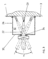
- the seal 35 is so elastic that the jet lance 22 together with the acceleration tube 21 can be given a limited conical pendulum movement within the interior 32 of the jet bell 25 without breaking the vacuum in the interior of the jet bell 25 (see FIG. 3).
- the opening angle ⁇ of the cone is approximately 90 °.
- the back and forth movement of the jet lance 22 within the jet bell 25 can be observed through a viewing window 36 .
- the viewing window 36 is located above the lead-through opening 34 of the blasting lance 22 in the front wall 33 of the blasting chamber 25 and is made of glass. So that the blasting chamber 25 can be moved from one treatment site to another treatment site, a ventilation valve 37 is arranged in the wall 26 , through which the blasting chamber 25 can be ventilated when the supply line 20 and the discharge line 28 are short-circuited.
- a stop 38 is pushed and locked onto the jet lance 22 , with which the distance a of the jet lance 22 including the nozzle 24 from the treatment surface can be adjusted.
- the beam spacing a can thus be set precisely.
- FIG. 4 shows the tangential integration of the vacuum derivation 28 into the interior of the container 10 .
- the acceleration tube 21 and the jet lance 22 are formed in one piece.
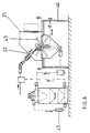
- the blasting chamber 25 is mounted on a table 40 and consists of a hemispherical hood 41 and a collecting funnel 42 attached to the hood 41 .
- a blasting table 43 in the form of a turntable.
- the drive axis CC of the beam table 43 is guided in the funnel axis DD , penetrates the collecting funnel 42 and is connected to a drive 44 , for example an electric motor, on the outside of the collecting funnel.
- a suction nozzle 45 perpendicular to the funnel axis DD , to which the vacuum discharge line 28 is connected.
- the vacuum discharge line 28 is connected to the unit 4 , which is attached to the head of the container 10 .
- a wetting device 46 which applies a cleaning liquid to the blasting agent, is integrated downstream of the acceleration pipe 21 in the underpressure feed line 20 .
- the blasting chamber 25 here has a pivotable blasting table 43 , the pivot axis of which is located in the connection plane BB .
- the jet table is driven by a drive 44 arranged in the collecting funnel 42 , which converts the rotary movement of the motor into a pendulum movement.
- the exhaust air of the unit 4 is returned to the vacuum feed line 20 via a heating or cooling device 47 .
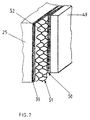
- FIG. 7 shows a flexible suction plate 49 which covers a surface 51 (wire mesh) with openings 52 opposite the jet bell 25 .
- the suction plate 49 is provided with a sealing layer 50 which seals against the walls of the jet bell due to the negative pressure applied in the jet bell 25 . Blasting media can then be applied to the wire mesh without any problems.
Description
Aus der DE-OS 29 16 131 ist eine Lösung zur Behandlung einer Oberfläche bekannt, die aus einem mit einem Schütt-Trichter unterends versehenen Behälter mit Auslaß zur Bevorratung eines Schleifmittels, einer das Schleifmittel auf die abzuschleifende Oberfläche lenkende Pistole, die von einem Kanal durchzogen ist, an dessen Ende eine Druckluftquelle angeschlossen ist, einer Zuleitung, die den Auslaß des Behälters mit dem Kanal in der Pistole an einer Stelle stromabwärts von der Verbindung mit der Druckluftquelle verbindet, eine in der Zuleitung nächst dem Auslaß angebrachte Öffnung, durch die der Atmosphärendruck mit der Zuleitung in Verbindung steht, so dass Druckluft, die durch den Kanal der Pistole und über das Ende der Zuleitung strömt, in der Zuleitung einen Unterdruck erzeugt, der Luft durch die Öffnung ansaugt, wodurch Schleifmittel aus dem Auslaß abgezogen und aus dem anderen Ende des Kanals der Pistole auf die zu behandelnde Oberfläche geschleudert wird.
Der Lauf der Pistole ist von einer Haube umgeben, die auf die zu behandelnde Fläche aufsetzbar ist. Von der Haube führt eine Rückleitung zum Behälter, an dem außerdem eine Vakuumquelle angeschlossen ist, die über dem bevorrateten Schleifmittel einen Unterdruck erzeugt, der das auf die behandelnde Fläche geschleuderte Strahlgut aus der Haube in den Behälter saugt.
Mit dieser bekannten Lösung werden zwei Kreisläufe realisiert, ein Unterdruckkreislauf zum Absaugen von gebrauchtem Strahlgut und ein Überdruckkreislauf, der das Strahlgut auf die notwendige Strahlgeschwindigkeit beschleunigt, wobei die Zudosierung des Strahlgutes in den Überdruckstrom mit durch den Überdruck erzeugten Unterdruck durchgeführt wird. Beide Kreisläufe sind voneinander durch das im Behälter bevorratete Strahlgut als Druckbarriere getrennt.
Bedingt durch den zum Teil erheblichen Überdruck erhalten die Strahlmittel eine hohe Auftreffenergie, die bei empfindlichem Untergrund, beispielsweise Kunststoffflächen zu einer Beeinträchtigung oder sogar zur Zerstörung führen können. Eine feinfühlige Ablösung ohne Beeinträchtigung des Untergrundes ist nicht möglich.
Ein weiterer Nachteil dieser bekannten Lösung besteht darin, dass eine Abtrennung der abgelösten Lackschichten vom Strahlgut nicht erfolgt, d.h. das kontaminierte Strahlgut muss verworfen und durch neues ersetzt werden.
Das Strahlgut ist nach dem Strahlen mit dem abgelösten Material kontaminiert. Eine Trennung erfolgt nicht, so dass auch bei dieser bekannten technischen Lehre
das Strahlgut verworfen werden oder gesondert aufgearbeitet werden muss. Der durch den Überdruck beschleunigte Strahlgutstrom ist äußerst energiereich und für die Ablösung von Beschichtungen auf problembehafteten weichen Untergründen nicht geeignet, weil keine Regulierung der Strahlenergie möglich ist.
Bei diesem bekannten Stand der Technik ist zwar eine Kreislauffahrweise des Strahlmittels realisiert, jedoch sind auch hier ein Kreislauf um verbrauchtes Strahlmittel mit Unterdruck abzusaugen und ein Kreislauf für die Beschickung einer Strahlturbine mit Schleuderrad erforderlich. Das Strahlmittel erhält seine Bewegungsenergie durch die Drehung des Schleuderrades, was apparate- und steuerungstechnisch sehr aufwendig ist. Für die Entfernung von beispielsweise Graffiti ist eine derartige Konstruktion viel zu kompliziert und energetisch zu aufwendig.
Die in diesem älteren Recht beschriebene Vorrichtung besteht aus einer allseitig im wesentlichen luftdicht geschlossenen Kammer mit mindestens einer, vorzugsweise mehreren verschließbaren Öffnungen, wobei die Kammer evakuierbar ist, einem Behälter zur Aufnahme von Strahlmittel, einer Strahlrohreinheit, die über eine der verschließbaren Öffnungen in die Kammer einführbar ist und die einen Zulaß für das Strahlmittel, einen Zulaß für Luft und eine Austrittsöffnung für das Strahlmittel aufweist, wobei der Zulaß für das Strahlmittel über eine Zuführleitung mit dem Strahlmittelbehälter verbindbar ist.
Die Strahlrohreinheit weist einen rohrförmigen Hauptteil mit einem Einlaß für das Strahlmittel, eine Lufteinlaßöffnung und eine Austrittsöffnung bzw. Düse für das Strahlmittel und die angesaugte Luft auf. Nach Einführung der Strahlrohreinheit durch eine der Öffnungen in der Kammer befindet sich die Lufteinlaßöffnung außerhalb der Kammer und die Luftaustrittsöffnung innerhalb der Kammer. Durch den an der Kammer mittels eines handelsüblichen angeschlossenen Staubsaugers wird durch die Lufteinlaßöffnung Umgebungsluft angesaugt, durch den in Kammer herrschenden Unterdruck Strahlmittel aus dem Behälter durch die Zuführleitung transportiert und aus der Austrittsöffnung der Strahlrohreinheit in die Kammer auf das zu bearbeitende Werkstück gelenkt. Mit dem Staubsauger wird die Luft und das Strahlgut aus der Kammer abgesaugt und vom Staubsaugerfilter aufgefangen.
Die in der DE 196 14 555 A1 beschriebene Lösung hat den Nachteil, dass die erreichten Strahlgeschwindigkeiten nur ausreichen, um kleinere Werkstücke zu säubern. Für größere Werkstücke bzw. Flächen ist diese Lösung nicht mehr geeignet. Außerdem kann der Strahlprozeß nur solange durchgeführt werden bis der Vorrat an Strahlmittel im Behälter aufgebraucht ist.
Das mit Verunreinigungen kontaminierte Strahlgut wird lediglich in die Staubsaugertüte entsorgt. Eine Trennung des Strahlgutes von den Kontaminationen erfolgt nicht, ebenso keine Rückführung des Strahlgutes in den Strahlkreislauf.
Für eine großflächige Strahlbehandlung von beispielsweise mit Graffiti-Besprühungen verunreinigte Flächen ist diese vorgeschlagene Lösung nicht geeignet. Dies trifft auch für größere Teile bzw. Werkstücke zu.
Diese Schrift bildet die Grundlage für die Oberbegriffe der Patentansprüche 1 und 17.
Mit dem erfindungsgemäßen Verfahren wird es damit möglich, die Bewegungsenergie der Strahlteilchen nach Art, Größe und Beschaffenheit der Beschichtung und des Untergrundes zu regeln.
Von besonderem Vorteil hat sich erwiesen, wenn der Strahlabstand von Strahllanze und Behandlungsfläche etwa das 0,1 bis 3,0fache des Innendurchmessers der Beschleunigungstrecke beträgt.
Je nach Art der Strahlteilchen und der erteilten Strahlgeschwindigkeit lassen sich mit dem erfindungsgemäßen Verfahren Beschichtungen auf Metall, Farbaufsprühungen auf Kunststoff, Beschriftungen auf Papier, Verwitterungsablagerungen auf Stein, Schmutzablagerungen auf Beton, wenn notwendig ohne Abtrag des Untergrundes oder aber mit Abtrag des Untergrundes auch Rostschichten von Metallen abrasiv entfernen. Die Abrasivität des erfindungsgemäßen Verfahrens hängt im entscheidenden Maße von der auf die Strahlteilchen übertragenden Strahlenergie und deren Art ab.
Das erfindungsgemäße Verfahren zeichnet sich dadurch aus, dass die Strahlenergie in Abhängigkeit der Untergrundbeschaffenheit, des Charakters des Strahlmittels und der Art der zu entfernenden Beschichtung variierbar ist, so dass auch problembehaftete Verschmutzungen, beispielsweise in Form von Übermalungen vom Untergrund gelöst werden können, ohne den Untergrund zu zerstören oder nennenswert anzugreifen.
Die Bearbeitungswirkung der Strahlteilchen wird erfindungsgemäß weiter verbessert, wenn die Strahlmittel vor ihrer Beschleunigung mit üblichen Reinigungsflüssigkeiten benetzt werden.
Vor allem bei Graffiti-Verschmutzungen von größeren Flächen wird eine Strahlkammer auf den zu bearbeitenden Untergrund dichtend und verschiebbar aufgesetzt, evakuiert und das Strahlmittel-Luftgemisch über die Behandlungsfläche hin- und herbewegt.
Die Verschiebebewegung der Strahlkammer von einer Behandlungsfläche zu einer anderen wird vorteilhafterweise bei anliegendem Unterdruck durchgeführt. Natürlich ist es auch möglich, ohne die Erfindung zu verlassen, die Verschiebebewegung der Strahlkammer bei kurzgeschlossenem Kreislauf unter Atmospärendruck durchzuführen.
Je nach geforderter Luftleistung sind diese ein- oder mehrstufig ausgelegt.
Besonders gute Bearbeitungseffekte in der Entfernung von beispielsweise dünnen Bemalungen auf Blechflächen werden erzielt, wenn dem Tragluftvolumenstrom 0,013% Strahlmittel zudosiert wird.
Die Länge der Beschleunigungsstrecke kann variabel ausgeführt sein, in dem ein ausziehbares Teleskoprohr das Beschleunigungsrohr bildet.
Die Dichtelemente bestehen vorzugsweise aus geschlossenzelligem Schaumgummi, Folien, Bürsten, Gummilippen, gefüllten Dichtelementen, Schläuchen aus Latex, Gummi oder Profildichtungen, die sich den Unebenheiten des Untergrundes leicht anpassen.
Für Problembereiche wie Ecken, Kanten oder gekrümmten Behandlungsflächen sind diese Wände zueinander konvex, konkav oder V-förmig ausgebildet oder mit Gelenken versehen, die sich an unterschiedliche Oberflächenbeschaffenheiten leicht anpassen.
Dies macht den Einsatz der erfindungsgemäßen Vorrichtung für Ecken- und Kantenbereiche besonders effektiv.
einen Absaugstutzen aufweisenden Sammeltrichter zusammengesetzt ist, und dass in der Anschlußebene zwischen Haube und Trichter ein Strahltisch angeordnet ist.
Es gehört natürlich zu der weiteren Ausgestaltung der Erfindung, wenn der Strahltisch ein Schwenkteller ist, der um eine in der Anschlußebene liegende Achse schwenkbar ist.
Mit einem derartig drehbar oder schwenkbar ausgebildeten Strahltisch lassen sich spezielle Werkstücke mit komplizierter Oberflächenstruktur und Form schnell und problemlos bearbeiten.
Je nach Untergrundbeschaffenheit und Art der Beschichtung bzw. Verschmutzung können unterschiedliche Düsengrößen auf der Strahllanze aufgesetzt werden, so dass die Beladung mit Strahlmittel im Tragluftstrom entsprechend variierbar ist.
In weiterer bevorzugter Ausgestaltung der erfindungsgemäßen Vorrichtung ist die Strahlkammer mit einem Sichtbereich, vorzugsweise einem Sichtfenster, versehen, der eine Beobachtung der Bewegung der Strahllanze und damit des Strahlvorganges im Innenraum der Strahlglocke ermöglicht. Das Sichtfenster befindet sich entweder oberhalb oder unterhalb der Strahllanze. Zweckmäßig ist es, wenn das Sichtfenster aus Glas oder Acrylglas besteht.
Alternativ kann natürlich die gesamte Strahlglocke aus durchsichtigem schlagzähen Kunststoff bestehen, so dass ein gesondertes Sichtfenster entfallen kann.
Geeignete unterdruckerzeugende Aggregate sind Naß- und/oder Trockensauger, Pumpen, Verdichter oder Gebläse, die nach einem bevorzugten weiteren Merkmal der Erfindung auf dem Behälter angeordnet und mit diesem direkt in Verbindung steht. Es ist aber auch möglich, das unterdruckerzeugende Aggregat in die Unterdruck-Ableitung einzubinden, ohne die Erfindung zu verlassen.
Natürlich gehört es auch zu den Merkmalen der erfindungsgemäßen Vorrichtung, wenn beide Behälter ein gemeinsames Gehäuse aufweisen, das nur durch den Schütt-Trichter in den Ausschleusungsraum und den Bevorratungsraum getrennt ist.
Der Wegfall des gesamten Überdruck- bzw. Hochdruckerzeugungssystems für die Druckluft führt zu erheblichen Einsparungen an aufzuwendender Energie.
- Fig. 1
- ein Funktionsschema des erfindungsgemäßen Verfahrens,
- Fig. 2
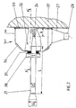
- einen Längsschnitt durch die Strahlglocke mit Beschleunigungsrohr und Strahllanze,
- Fig. 3
- einen Schnitt entlang der Linie A-A durch die Strahlglocke nach Fig. 2,
- Fig. 4
- die tangentiale Einbindung der Unterdruck- Zuleitung in den Behälter,
- Fig. 5
- eine Darstellung der erfindungsgemäßen Vorrichtung mit geschlossener Strahlkammer und Benetzungseinrichtung,
- Fig. 6
- eine Ausführungsvariante gemäß Fig. 5 mit zusätzlicher Heiz- oder Kühleinrichtung für den Ablauftstrom und
- Fig. 7
- eine perspektivische Ansicht der Ansaugplatte mit Drahtgeflecht und Strahlglocke.
Als Strahlmittel 2 wird Natriumhydrogencarbonat (Backpulver) verwendet.
Mit einem handelsüblichen dreistufigen Naß-Trockensauger 4 wird ein Tragluftvolumenstrom 5 mit einer Luftleistung von ca. 230 m3/h erzeugt. Der Saugstutzen 6 des Nass-Trockensaugers 4 ist mit einer Saugleitung 7 verbunden, die über einen Anschluss 8 mittig im Dach 9 eines Behälters 10 einbindet und in diesem ein Unterdruck von ca. 80 mbar erzeugt. Der Behälter 10 ist auf den Behälter 11 für die Bevorratung des Strahlmittels 2 in vertikaler Flucht
aufgesetzt. In beiden Behältern 10 und 11 sind die Behälterböden durch einen konischen Schütt-Trichter 12 bzw. 13 mit einem Öffnungswinkel α von jeweils 90° gebildet.
In der Öffnung 14 des Schütt-Trichters 12 befindet sich ein Schließorgan 15, in diesem Ausführungsbeispiel ein Schieber, der den Behälter 10 vom Behälter 11 pneumatisch abschottet.
Der Behälter 11 hat eine zur Außenatmosphäre hin geöffnete Fremdbelüftung 16, so dass bei geöffnetem Schieber 15 das Strahlmittel 2 durch seine Schwerkraft in den darunter befindlichen Schütt-Trichter 13 des Behälters 11 fallen kann.
An die Öffnung 17 des Schütt-Trichters 13 ist in vertikaler Flucht eine Dosiereinrichtung 18 mit horizontal liegendem Injektor 19 angeschlossen, der mit der Unterdruck-Zuleitung 20 verbunden ist. Das Strahlmittel 2 fällt durch seine Schwerkraft über die Dosiereinrichtung 18 in den Injektor 19, wird durch den anliegenden Unterdruck zusätzlich angesaugt und strömt zusammen mit dem Tragluftvolumenstrom als Tragluft-Strahlmittel-Gemisch in der flexiblen Unterdruck-Zuleitung 20 einem starren geradlinig verlaufenden Beschleunigungsrohr 21 zu. Die durch Schwerkraft und Unterdruck zudosierte Menge an Strahlmittel beträgt 0,013% des Tragluftvolumenstromes.
Das Beschleunigungsrohr 21 hat einen Innendurchmesser d2 von 20 mm, die Unterdruck-Zuleitung 20 einen Innendurchmesser d1 von 32 mm, so dass eine Querschnittsverringerung
von der Unterdruck-Zuleitung 20 zum Beschleunigungsrohr 21 erfolgt. Das Durchmesserverhältnis d2:d1 beträgt für das hier gewählte Beispiel 0,625.
Das Beschleunigungsrohr 21 bildet eine Beschleunigungsstrecke L, in der die Strahlteilchen des Strahlmittels 2 auf eine Strahlgeschwindigkeit von etwa 60 m/s beschleunigt werden. Die Beschleunigungsstrecke L hat für diesen Anwendungsfall eine Länge von 60 cm.
Das Beschleunigungsrohr 21 ist mit einer Strahllanze 22 lösbar verbunden. Die Strahllanze 22 trägt an ihrer der Behandlungsfläche zugewandten Öffnung 23 eine Düse 24, durch die das Strahlmittel-Tragluftgemisch auf die Behandlungsfläche gelenkt wird.
Die Strahllanze 22 führt in eine als Glocke ausgebildete Strahlkammer 25, die die Behandlungsfläche auf der Wand gegen die Atmosphäre abschottet.
In der Strahlkammer 25 liegt demzufolge ein entsprechender Unterdruck an, der ausreicht, dass die Strahlkammer 25 mit ihren Wänden 26 auf der Behandlungsfläche angesaugt wird.
Die Strahlkammer 25 besitzt einen trichterartigen Absaugstutzen 27, an dem eine flexible Unterdruck-Ableitung 28 angeschlossen ist. Die Unterdruck-Ableitung 28 führt zurück in den Behälter 10 und bindet in diese ein. Damit ist Kreislauf geschlossen.
Das Strahlmittel-Luftgemisch wird durch die Unterdruck-Zuleitung 20 befördert, in der Beschleunigungsstrecke L soweit beschleunigt, dass die Strahlteilchen eine für die schonende Ablösung der Beschichtung ausreichende Energie erhalten, strömt dann durch Strahllanze 22 und wird durch die Düse 24 zielgerichtet auf die Behandlungsfläche geschleudert. Das mit Staub und abgelösten Beschichtungsteilchen versetzte Strahlmittel-Luftgemisch strömt anschließend durch die Unterdruck-Ableitung 28 in den Behälter 10 zurück, und wird dort tangential entlang des Behältermantels 29 in den Abscheider 48 des Behälters 10 eingesaugt. Das beladene kontaminierte Strahlmittel-Luftgemisch wird dadurch in Rotation versetzt. Da die Strahlteilchen des Strahlmittels eine weitaus höhere Masse aufweisen und damit höhere Energie haben, fallen die Strahlteilchen am inneren Behältermantel 29 herunter und in den Schütt-Trichter 12 und sammeln sich dort.
Der dann noch mit feinsten Staub- oder Beschichtungsteilchen kontaminierte Tragluftvolumenstrom wird durch die Saugleitung 7 angesaugt. Staub und Beschichtungsteilchen werden im Naß-Trockensauger abgeschieden und der gereinigte Tragluftvolumenstrom in den Kreislauf zurückgeführt.
Für den Fall, dass die Strahlkammer 25 umgesetzt werden muss oder die Unterdruck-Zuleitung 20 und/oder die Unterdruck-Ableitung 28 verstopfen, sind beide Leitungen unter Umgehung der Strahlkammer 25 durch eine Leitung 30 kurzgeschlossen. Die Leitung 30 ist dazu an ihren Einbindungsstellen mit Absperrventilen 31 versehen.
Die Stirnseiten ihrer Wände 26 sind mit Dichtelementen 39 aus geschlossenzelligem Schaumstoff versehen, die sich bei Anlegen eines Unterdruckes dicht an die Wand anpressen, so dass sich im Innenraum 32 der Strahlkammer 25 ein entsprechender Unterdruck einstellt.
In der Vorderwand 33 der Stahlkammer 25 ist eine Öffnung 34 eingearbeitet, durch die die Strahllanze 22 mit aufgesetzter Düse 24 abgedichtet hindurchgeführt ist. Die Strahllanze 22 ist von einer Dichtung 35 umschlossen, die ihrerseits die Öffnung 34 umgrenzende Vorderwand 33 umschließt. Die Dichtung 35 ist so elastisch, dass der Strahllanze 22 zusammen mit dem Beschleunigungsrohr 21 eine begrenzte kegelförmige Pendelbewegung innerhalb des Innenraumes 32 der Strahlglocke 25 erteilt werden kann, ohne das Vakuum im Innenraum der Strahlglocke 25 zu brechen (s. Fig. 3). Der Öffnungswinkel γ des Kegels beträgt etwa 90°.
Damit die Strahlkammer 25 von einer Behandlungsstelle zu einer anderen Behandlungsstelle umgesetzt werden kann, ist in der Wand 26 ein Belüftungsventil 37 angeordnet, durch das bei kurzgeschlossener Zuleitung 20 und Ableitung 28 die Strahlkammer 25 belüftbar ist.
Auf die Strahllanze 22 ist ein Anschlag 38 aufgeschoben und arretiert, mit der der Abstand a der Strahllanze 22 incl. Düse 24 von der Behandlungsfläche einstellbar ist.
Je nach Untergrundbeschaffenheit, der Art der zu entfernenden Beschichtung lässt sich somit der Strahlabstand a genau einstellen.
Gegenüber der Variante nach Fig. 5 wird die Abluft des Aggregates 4 über eine Heiz- bzw. Kühleinrichtung 47 der Unterdruck-Zuleitung 20 zurückgeführt.
| Beschichtung | 1 |
| Strahlmittel | 2 |
| Wandfläche | 3 |
| Naß-Trockensauger | 4 |
| Tragluftvolumenstrom | 5 |
| Saugstutzen | 6 |
| Saugleitung | 7 |
| Anschluß | 8 |
| Dach von 10 | 9 |
| Behälter | 10 |
| Behälter für Bevorratung | 11 |
| Schütt-Trichter von 10 | 12 |
| Schütt-Trichter von 11 | 13 |
| Öffnung in 12 | 14 |
| Schließorgan/Schieber in 14 | 15 |
| Fremdbelüftung | 16 |
| Öffnung in 13 | 17 |
| Dosiereinrichtung | 18 |
| Injektor | 19 |
| Unterdruck-Zuführung | 20 |
| Beschleunigungsrohr | 21 |
| Strahllanze | 22 |
| Öffnung in der Strahllanze | 23 |
| Düse | 24 |
| Strahlkammer | 25 |
| Wände von 25 | 26 |
| Absaugstutzen | 27 |
| Unterdruck-Ableitung | 28 |
| Behältermantel von 10 | 29 |
| Kurzschlußleitung | 30 |
| Absperrventil | 31 |
| Innenraum von 25 | 32 |
| Vorderwand von 25 | 33 |
| Öffnung in 33 | 34 |
| Dichtung | 35 |
| Sichtfenster | 36 |
| Belüftungsventil | 37 |
| Anschlag | 38 |
| Dichtelemente | 39 |
| Tisch | 40 |
| Haube | 41 |
| Sammeltrichter | 42 |
| Strahltisch | 43 |
| Antrieb | 44 |
| Ansaugstutzen | 45 |
| Benetzungseinrichtung | 46 |
| Heiz-oder Kühleinrichtung | 47 |
| Abscheider | 48 |
| Ansaugplatte | 49 |
| Beschichtung von 49 | 50 |
| Drahtgeflecht | 51 |
| Öffnungen von 51 | 52 |
| Anschlußebene | B-B |
| Antriebsachse | C-C |
| Trichterachse | D-D |
| Strahlabstand | a |
| Beschleunigungsstrecke | L |
| Innendurchmesser der Schlauchzuleitung | d1 |
| Innendurchmesser des Beschleunigungsrohrs | d2 |
| Öffnungswinkel der Schütt-Trichter | α |
| Winkel der Pendelbewegung | γ |
Claims (54)
- Verfahren zum Bearbeiten, insbesondere Reinigen, Abtrennen von Beschichtungen, Graffiti oder sonstigen oberflächlichen Verunreinigungen auf Teilen bzw. Werkstücken oder Flächen aus Stein, Beton, Holz, Metall, Kunststoff, Glas, Keramik oder Papier, bei dem ein Strahlmittel durch Schwerkraft aus einem Bevorratungsbehälter in einen innerhalb eines aus Zu- und Ableitungen gebildeten Schlauchleitungssystems geführten Tragluftstrom eingebracht, mittels Unterdruck durch diesen befördert, und gegen die zu behandelnde Fläche in einer Strahlkammer durch eine Strahllanze geschleudert, von dort in den Tragluftstrom so zurückbefördert wird, dass das Strahlmittel im Kreislauf gefahren wird, wobei die Beschleunigung des Strahlmittels im wesentlichen durch den an der Strahlkammer anliegenden Unterdruck und durch die Erhöhung der Strahlgeschwindigkeit mittels Durchmesserverringerung von der Zuleitung auf die Strahllanze erzeugt wird, dadurch gekennzeichnet, dass der Unterdruck im Kreislauf auf 50 bis 300 mbar eingestellt, das Strahlmittel dem Tragluftvolumenstrom in einer auf den Tragluftvolumenstrom bezogenen Menge von 0,01 bis 25,0% mit oder ohne Reinigungsflüssigkeit zudosiert, der Energieeintrag auf die zu bearbeitenden Teile mittels Einstellung der Strahlgeschwindigkeit des Strahlmittels von 20 bis 80 m/s durch Durchmesserverringerung in Abhängigkeit der zu entfernenden Beschichtungen gesteuert, sodann das Strahlmittel-Luftgemisch mit einer sich rhythmisch wiederholenden Hin- und Herbewegung über die Behandlungsfläche hinweg unter Beobachtung gerichtet oder die Behandlungsfläche im Strahlmittel-Luftgemisch in Rotation versetzt und/oder verschwenkt wird, das Strahlmittel nach seiner Abtrennung und Sammlung ggf. getrocknet und das verbleibende Kontamination-Luftgemisch einer Feinreinigung im Naß- und/oder Trockensauger unterworfen wird, und dass Frischluft und/oder wahlweise die abgetrennte Luft alsdann gekühlt oder aufgeheizt dem Unterdruck-Kreislauf erneut zugeführt wird.
- Verfahren nach Anspruch 1, dadurch gekennzeichnet, dass die Beschleunigung in einer geradlinig verlaufenden Beschleunigungsstrecke innerhalb der Unterduck-Zuleitung durchgeführt wird.
- Verfahren nach Anspruch 1 und 2, dadurch gekennzeichnet, dass die Beschleunigung der Strahlmittel durch eine Durchmesserverringerung des Beschleunigungsrohres auf das 0,1 bis 0,9fache des Durchmessers (d1) der Unterdruck-Zuleitung (20) über eine Länge des 5 bis 50fachen Innendurchmessers (d2) der durchmesserverringerten Unterdruck-Zuleitung (20) eingestellt wird.
- Verfahren nach Anspruch 3, dadurch gekennzeichnet, dass die Strahlgeschwindigkeit der Strahlmittel bei konstantem Volumenstrom aus Luft und Strahlmittel durch Veränderung der Durchmesserverhältnisse (d2:d1) und/oder der Länge (L) der Beschleunigungsstrecke und/oder des Strahlabstandes (a) der Strahllanze (22) mit der Düse (24) von der Behandlungsfläche und der Rotationsgeschwindigkeit der Behandlungsfläche gesteuert wird.
- Verfahren nach Anspruch 4, dadurch gekennzeichnet, dass der Strahlabstand (a) etwa das 0,1 bis 1,0fache des Innendurchmessers (d2) des Beschleunigungsrohres beträgt.
- Verfahren nach Anspruch 1 bis 5, dadurch gekennzeichnet, dass die Beschleunigung vor Eintritt in die Strahlkammer in einem eine Beschleunigungsstrecke (L) bildenden Beschleunigungsrohr durchgeführt wird.
- Verfahren nach Anspruch 1 bis 6, dadurch gekennzeichnet, dass die Beschleunigungsstrecke (L) bis in die Strahlkammer hineinreicht.
- Verfahren nach Anspruch 1 bis 7, dadurch gekennzeichnet, dass die Hin-und Herbewegung des Strahlmittel-Luftgemisches mittels einer Pendel- und/oder Schwenkbewegung der Strahllanze durchgeführt wird.
- Verfahren nach Anspruch 1, dadurch gekennzeichnet, dass die Strahlkammer auf die zu bearbeitende Fläche dichtend aufgesetzt, durch den Unterdruck evakuiert und nach Bearbeitung von der behandelten Fläche zu einer unbehandelten Fläche verschoben wird.
- Verfahren nach Anspruch 9, dadurch gekennzeichnet, dass die Verschiebebewegung bei anliegendem Unterdruck durchgeführt wird.
- Verfahren nach Anspruch 9, dadurch gekennzeichnet, dass die Verschiebebewegung bei kurzgeschlossenem Kreislauf (K) unter Atmosphärendruck durchgeführt wird.
- Verfahren nach Anspruch 1, dadurch gekennzeichnet, dass zur Unterdruckerzeugung im offenen Kreislauf (K) Naß- und/oder Trockensauger, Pumpen, Verdichter oder Gebläse verwendet werden.
- Verfahren nach Anspruch 1 bis 12, dadurch gekennzeichnet, dass ein Tragluftvolumenstrom von etwa 150 bis 400 m3/h, vorzugsweise 230 m3/h, eingestellt wird.
- Verfahren nach Anspruch 1 bis 13, dadurch gekennzeichnet, dass die unterdruckerzeugenden Aggregate ein- oder mehrstufig ausgelegt sind.
- Verfahren nach einem oder mehreren der vorherigen Ansprüche, dadurch gekennzeichnet, dass die Zudosierung des Strahlmittels in den Tragluftvolumenstrom auf vorzugsweise 0,013% des Tragluftvolumenstromes eingestellt wird.
- Verfahren nach einem oder mehreren der vorherigen Ansprüche, dadurch gekennzeichnet, dass als Strahlmittel Natriumhydrogencarbonat, Kunststoffteilchen, vorzugsweise Duroplastteilchen, Asche, zerkleinerte feinkörnige Schlacke, Korund, Quarz, metallische Teilchen, Glasperlen, pflanzliche/organische Teilchen oder deren Gemische verwendet werden.
- Vorrichtung zur Durchführung des Verfahrens nach Anspruch 1, mit einem an seinem unteren Ende konisch als Schütt-Trichter (13) mit Auslauföffnung (14) ausgebildeten Behälter (11) für die Bevorratung eines fein- und/oder grobkörnigen Strahlmittels, das durch seine Schwerkraft in die Auslaßöffnung des Schütt-Trichters gelangt, welche an eine flexible Zuleitung (20) zum Transport des Strahlmittels in eine mit einem Unterdruck erzeugenden Aggregat (4) evakuierbare, die Teile oder Flächen aufnehmende Strahlkammer (25) angeschlossen ist, die ihrerseits mit einer Unterdruck-Ableitung (28) verbunden ist, die mit mindestens einem auf dem Schütt-Trichter (13) des Behälters (11) angeordneten weiteren Behälter (10) verbunden ist, der seinerseits einen konisch ausgebildeten Schütt-Trichter (12) aufweist und mit dem unterdruckerzeugenden Aggregat in Verbindung steht, wobei die Unterdruck-Ableitung (28) tagential durch den Behältermantel (29) in einen im Kopf des Behälters (10) angeordneten Abscheider (10) einbindet, wobei durch eine Öffnung (34) in der Strahlkammer (25) eine an die Unterdruck-Zuleitung (20) angeschlossene, eine Düse (24) tragende Strahllanze (22) geführt ist, wobei die Unterdruck-Zuleitung (20) mit einer Dosiereinrichtung (18) und/oder einem Injektor (19) für die Dosierung des Strahlmittels in den Kreislauf versehen und mit einem, eine Beschleunigungsstrecke (L) bildenden geradlinig verlaufenden Beschleunigungsrohr (21) verbunden ist, das der Strahllanze vorgeordnet ist und das gegenüber der Zuleitung eine weitere Durchmesserverrringerung aufweist, ist, gekennzeichnet durch folgende Merkmale,a) in die Unterdruck-Zuleitung ist stromabwärts gelegen eine ein- und auskoppelbare Benetzungseinrichtung (46) für die Benetzung des Strahlmittels mit Reinigungsflüssigkeit eingebunden undb) der Austrittsstutzen (45) des Aggregates (4) für die Abluft ist über eine Kühl- oder Heizeinrichtung (47) mit der Unterdruck-Zuleitung (20) zu- und abschaltbar verbunden.
- Vorrichtung nach Anspruch 17, dadurch gekennzeichnet, dass das Beschleunigungsrohr (21) sich über eine Länge (L) des 5 bis 50fachen Innendurchmessers (d1) der Unterdruck-Zuleitung (20) erstreckt und einen Innendurchmesser (d2) aufweist, der das 0,1 bis 0,9fache des Innendurchmessers (d1) der Unterdruck-Zuleitung (20) beträgt.
- Vorrichtung nach Anspruch 17 und 18, dadurch gekennzeichnet, dass das Beschleunigungsrohr (21) direkt an die Dosiereinrichtung (18) und/oder den Injektor (19) angeschlossen ist.
- Vorrichtung nach Anspruch 17 bis 19, dadurch gekennzeichnet, dass das Beschleunigungsrohr (21) als ein ausziehbares Teleskoprohr ausgebildet ist.
- Vorrichtung nach einem oder mehreren der vorherigen Ansprüche 18 bis 20, dadurch gekennzeichnet, dass die Strahllanze (22) am Beschleunigungsrohr (21) lösbar und auswechselbar befestigt ist.
- Vorrichtung nach einem oder mehreren der vorherigen Ansprüche 17 bis 20, dadurch gekennzeichnet, dass die in die Strahlkammer (25) hineinreichende Strahllanze (22) in der Öffnung (34) der Strahlkammerwand (26) in einem Kegel von annähernd 90° verschwenkbar und auf unterschiedliche Strahlabstände (a) einstellbar angeordnet ist.
- Vorrichtung nach Anspruch 17, dadurch gekennzeichnet, dass die Unterdruck-Zuleitung (20) und Unterdruck-Ableitung (28) durch eine absperrbare Kurzschlußleitung (30) unter Umgehung der Strahlkammer (25) miteinander verbunden sind.
- Vorrichtung nach Anspruch 17, dadurch gekennzeichnet, dass das Innere der Strahlkammer (25) durch eine Beleuchtung (53) von außen einsehbar ausgebildet ist und ein Belüftungsventil (37) aufweist.
- Vorrichtung nach Anspruch 17, dadurch gekennzeichnet, dass der Behälter (11) mit einer zur Atmosphäre hin geöffneten Fremdbelüftung (16) versehen ist.
- Vorrichtung nach Anspruch 17, dadurch gekennzeichnet, dass der weitere Behälter (10) durch ein in der Auslaßöffnung (14) des Schütt-Trichters (12) angeordnetes Schließorgan (15) vom Behälter (11) absperr- und öffnungsbar ist.
- Vorrichtung nach Anspruch 17, dadurch gekennzeichnet, dass die Strahlkammer (25) mit einem Sammeltrichter (27) versehen ist, an dem ein Absaugstutzen zum Anschluß der Unterdruck-Ableitung (28) angeordnet ist.
- Vorrichtung nach Anspruch 17 und 27, dadurch gekennzeichnet, dass die Strahlkammer (25) aus einer einseitig offenen Strahlglocke besteht, deren offenen Seite auf die Behandlungsfläche dichtend und bei anliegendem Unterdruck verfahrbar aufgesetzt angeordnet ist.
- Vorrichtung nach Anspruch 17, 27 und 28, dadurch gekennzeichnet, dass der offenen Seite der Strahlglocke eine Ansaugplatte (49) zur Abdichtung gegen eine mit Öffnungen (52) versehene Fläche (51), beispielsweise Drahtgeflecht, zugeordnet ist, wobei die Ansaugplatte die Öffnungen der zu behandelnden Fläche abdeckt.
- Vorrichtung nach Anspruch 29, dadurch gekennzeichnet, dass die Ansaugplatte (49) flexibel ausgebildet ist und eine Abdichtschicht (50) aus geschlossenzelligem Schaumgummi aufweist.
- Vorrichtung nach Anspruch 28 bis 30, dadurch gekennzeichnet, dass die auf die Behandlungsstelle aufgesetzten Glockenwände (26) mit Dichtelementen (39) versehen sind.
- Vorrichtung nach Anspruch 31, dadurch gekennzeichnet, dass die Dichtelemente (39) aus geschlossenzelligem Schaumgummi, Folien, Bürsten, Gummilippen, gefüllten Dichtelementen, Schläuchen aus Latex, Gummi oder Profildichtungen bestehen.
- Vorrichtung nach einem oder mehreren der vorherigen Ansprüche 17 bis 32, dadurch gekennzeichnet, dass die Strahlglocke (25) Wände besitzt, deren Stirnflächen zueinander eben ausgebildet sind.
- Vorrichtung nach einem oder mehreren der vorherigen Ansprüche 17 bis 33, dadurch gekennzeichnet, dass die auf gekrümmt oder eckig ausgebildeten Behandlungsflächen aufsetzbare Strahlglocke (25) Wände (26) besitzt, die zueinander konvex, konkav oder v-förmig ausgebildet sind oder Gelenke aufweist, die an unterschiedliche Oberflächenbeschaffenheit anpassbar sind.
- Vorrichtung nach Anspruch 17, dadurch gekennzeichnet, dass die Strahlkammer (25) geschlossen ausgebildet und aus einer stationär aufgestellten Haube (41) und einem an die Haube (41) angesetzten, einen Absaugstutzen aufweisenden Sammeltrichter (42) zusammengesetzt ist, und dass in der Anschlußebene (B-B) zwischen Haube (41) und Trichter (42) ein Strahltisch (43) angeordnet ist.
- Vorrichtung nach Anspruch 17 und 35, dadurch gekennzeichnet, dass der Strahltisch (43) ein Drehteller ist, dessen Antriebsachse (C-C) in der Trichterachse (D-D) angeordnet und mit einem am Sammeltrichter (42) befestigten Antrieb verbunden ist.
- Vorrichtung nach Anspruch 17 und 35, dadurch gekennzeichnet, dass der Strahltisch (43) ein Schwenkteller ist, der um eine in der Anschlußebene (B-B) liegende Achse schwenkbar ist.
- Vorrichtung nach einem oder mehreren der vorherigen Ansprüche 17 bis 37, dadurch gekennzeichnet, dass die Strahlkammer (25) mit einem Sichtfenster (36) aus Glas oder Acrylglas versehen ist, das über oder unter der Strahllanze (22) in der Vorderwand (33) angeordnet ist.
- Vorrichtung nach einem oder mehreren der vorherigen Ansprüche 17 bis 37, dadurch gekennzeichnet, dass die Strahlkammer (25) mit mindestens einer Beschickungsöffnung (44) versehen ist.
- Vorrichtung nach Anspruch 17, dadurch gekennzeichnet, dass die Strahlkammer (25) aus schlagzähem Kunststoff, vorzugsweise Polyamid oder Polypropylen, besteht.
- Vorrichtung nach einem oder mehreren der vorherigen Ansprüche 17 bis 40, dadurch gekennzeichnet, dass die Strahllanze (22) und das Beschleunigungsrohr (21) einstückig ausgebildet sind.
- Vorrichtung nach einem oder mehreren der vorherigen Ansprüche 17 bis 41, dadurch gekennzeichnet, dass die Strahllanze (22) mit einer auswechselbaren Düse (24) versehen ist.
- Vorrichtung nach einem oder mehreren der vorherigen Ansprüche 17 bis 42, dadurch gekennzeichnet, dass die Strahllanze (22) mit einem verstellbaren Anschlag (38) versehen ist.
- Vorrichtung nach einem oder mehreren der vorherigen Ansprüche 17 bis 43, dadurch gekennzeichnet, dass die Strahllanze (22) mit einem abgedichteten Kugelgelenk in der Öffnung (34) der Vorderwand (33) der Strahlkammer (25) angeordnet ist.
- Vorrichtung nach einem oder mehreren der vorherigen Ansprüche 17 bis 44, dadurch gekennzeichnet, dass die Strahllanze (22) in der Öffnung (34) der Vorderwand (33) der Strahlkammer durch eine Dichtung (35) hindurchführbar gehalten ist.
- Vorrichtung nach Anspruch 45, dadurch gekennzeichnet, dass die Dichtung (35) ein Simmering ist.
- Vorrichtung nach Anspruch 46, dadurch gekennzeichnet, dass die Dichtung (35) an die Vorderwand (33) angeflanscht ist.
- Vorrichtung nach Anspruch 17, dadurch gekennzeichnet, dass das unterdruckerzeugende Aggregat (4) ein Naß- und/oder Trockensauger, eine Pumpe, ein Verdichter oder Gebläse ist.
- Vorrichtung nach Anspruch 17, dadurch gekennzeichnet, dass das unterdruckerzeugende Aggregat (4) über eine Saugleitung (7) mit dem Behälter (10) in Verbindung steht.
- Vorrichtung nach Anspruch 17, dadurch gekennzeichnet, dass das unterdruckerzeugende Aggregat (4) auf dem Behälter (10) angeordnet und direkt mit diesem in Verbindung steht.
- Vorrichtung nach Anspruch 17, dadurch gekennzeichnet, dass das unterdruckerzeugende Aggregat (4) in die Unterdruck-Ableitung (28) eingebunden ist.
- Vorrichtung nach Anspruch 17, dadurch gekennzeichnet, dass das Schließorgan (15) ein Schieber, ein Ventil, eine Klappe, Blende, Schnecke oder Zellradschleuse ist.
- Vorrichtung nach einem oder mehreren der vorherigen Ansprüche 17 bis 52, dadurch gekennzeichnet, dass die Schütt-Trichter (12;13) in den Behältern (10;11) einen Öffnungswinkel (α) von 60 bis 120° aufweisen.
- Vorrichtung nach einem oder mehreren der vorherigen Ansprüche 17 bis 53, dadurch gekennzeichnet, dass die Behälter (10;11) ein gemeinsames Gehäuse besitzen.
Applications Claiming Priority (3)
| Application Number | Priority Date | Filing Date | Title |
|---|---|---|---|
| DE19747838A DE19747838C2 (de) | 1997-10-19 | 1997-10-19 | Verfahren und Vorrichtung zum trockenen Entfernen von Beschichtungen, Graffiti oder sonstigen oberflächlichen Verunreinigungen |
| DE19747838 | 1997-10-19 | ||
| PCT/DE1998/003106 WO1999020435A1 (de) | 1997-10-19 | 1998-10-19 | Verfahren und vorrichtung zum bearbeiten, insbesondere reinigen, abrasiven abtragen oder abtragen von beschichtungen, graffiti oder sonstigen oberflächlichen verunreinigungen auf teilen, werkstücken oder flächen |
Publications (2)
| Publication Number | Publication Date |
|---|---|
| EP1027188A1 EP1027188A1 (de) | 2000-08-16 |
| EP1027188B1 true EP1027188B1 (de) | 2002-07-31 |
Family
ID=7847026
Family Applications (1)
| Application Number | Title | Priority Date | Filing Date |
|---|---|---|---|
| EP98959753A Expired - Lifetime EP1027188B1 (de) | 1997-10-19 | 1998-10-19 | Verfahren und vorrichtung zum bearbeiten, insbesondere reinigen, abrasiven abtragen oder abtragen von beschichtungen, graffiti oder sonstigen oberflächlichen verunreinigungen auf teilen, werkstücken oder flächen |
Country Status (10)
| Country | Link |
|---|---|
| US (1) | US6390898B1 (de) |
| EP (1) | EP1027188B1 (de) |
| AT (1) | ATE221431T1 (de) |
| BR (1) | BR9815299A (de) |
| CA (1) | CA2347041C (de) |
| DE (2) | DE19747838C2 (de) |
| HU (1) | HUP0100361A3 (de) |
| PL (1) | PL187675B1 (de) |
| PT (1) | PT1027188E (de) |
| WO (1) | WO1999020435A1 (de) |
Cited By (1)
| Publication number | Priority date | Publication date | Assignee | Title |
|---|---|---|---|---|
| CN108136565A (zh) * | 2015-10-09 | 2018-06-08 | 奥迪股份公司 | 用于处理构件的表面的方法 |
Families Citing this family (69)
| Publication number | Priority date | Publication date | Assignee | Title |
|---|---|---|---|---|
| FR2801827B1 (fr) * | 1999-12-02 | 2002-02-01 | Etienne Lebourg | Procede de decapage permettant de peindre des meubles |
| GB2362314A (en) * | 2000-05-16 | 2001-11-21 | Harold Walmsley | Method and apparatus for cleaning up graffiti |
| ES2199002B1 (es) * | 2000-09-28 | 2005-07-16 | Business Machine World, S.L. | Maquina para grabacion indeleble en superificies diversas y para otros usos. |
| GB2367777A (en) * | 2000-10-10 | 2002-04-17 | Peter Reynolds | Blast processing using turbine blowers |
| ATE264729T1 (de) * | 2000-10-20 | 2004-05-15 | Ant Applied New Technologies A | Verfahren zum befüllen eines druckbehälters und vorrichtung zur erzeugung eines strahls einer suspension |
| DE10102924C1 (de) * | 2001-01-23 | 2002-06-13 | Pieper Innovationsgmbh | Verfahren und Vorrichtung zum Strahlbearbeiten, insbesondere formgenauen Abtragen und/oder Verdichten und/oder Beschichten, von festen Flächen |
| DE10113599A1 (de) * | 2001-03-20 | 2002-10-02 | Fisba Optik Ag St Gallen | Vorrichtung zur abrasiven Bearbeitung von Flächen von optischen Elementen |
| US20030032370A1 (en) * | 2001-04-10 | 2003-02-13 | Balcar Gerald P. | Process for reclaiming mirror cullet and production of a powdered glass |
| ITPD20020309A1 (it) * | 2002-12-04 | 2004-06-05 | Solvay Chimica Italia Spa | Impianto per pulitura industriale con cabina |
| ES2237265B1 (es) * | 2003-02-25 | 2006-07-16 | Jose Luis Torres Cuadra | Disposicion de limpieza y desincrustacion de materias y productos contaminantes de superficies en general. |
| DE102005005638B3 (de) * | 2005-02-05 | 2006-02-09 | Cryosnow Gmbh | Verfahren und Vorrichtung zum Reinigen, Aktivieren oder Vorbehandeln von Werkstücken mittels Kohlendioxidschnee-Strahlen |
| WO2006097134A1 (fr) * | 2005-03-14 | 2006-09-21 | Workinter Limited | Sabot et engin de decapage de surfaces pouvant presenter une courbure par projection et evacuation orientees d'un flux de particules |
| US20060219825A1 (en) * | 2005-04-05 | 2006-10-05 | United Materials International | High pressure fluid/particle jet mixtures utilizing metallic particles |
| DE102006009855A1 (de) * | 2006-03-03 | 2007-09-06 | Alfred Kärcher Gmbh & Co. Kg | Hochdruckreinigungsgerät und Verfahren zu seiner Steuerung und Regelung |
| JP4688063B2 (ja) * | 2006-03-17 | 2011-05-25 | 株式会社日立プラントテクノロジー | ブラスト媒体の回収装置 |
| AT504055B1 (de) * | 2006-07-25 | 2008-10-15 | Ge Jenbacher Gmbh & Co Ohg | Einrichtung zur reinigung eines brennraumes |
| SE531162C2 (sv) * | 2007-06-27 | 2009-01-07 | Jm Graffiti Remover Ab | Rengöringsanordning |
| US9039487B2 (en) * | 2008-08-07 | 2015-05-26 | Fuji Manufacturing Co., Ltd. | Blasting method and apparatus having abrasive recovery system, processing method of thin-film solar cell panel, and thin-film solar cell panel processed by the method |
| DE102008060776A1 (de) | 2008-12-05 | 2010-06-10 | Meissner, Werner | Industrielle Anlage zum Behandeln eines Werkstücks |
| DE102009010932A1 (de) | 2009-02-27 | 2010-09-02 | Meissner, Werner | Industrielle Reinigungsanlage mit Reinraumatmosphäre |
| WO2010122851A1 (ja) * | 2009-04-21 | 2010-10-28 | シャープ株式会社 | ブラスト装置およびブラスト加工方法 |
| WO2011014913A1 (en) * | 2009-08-04 | 2011-02-10 | Andrew Hill | Portable containment device |
| US8668554B2 (en) * | 2010-02-24 | 2014-03-11 | Werner Hunziker | Blasting nozzle for a device for blast-machining or abrasive blasting objects |
| DE102010020691B4 (de) * | 2010-05-17 | 2014-09-04 | Pieper Innovationsgesellschaft Mbh | Verfahren und Vorrichtung zum Fördern und Dosieren von Schüttgut beim Vakuumsaugstrahlen |
| GB2487742B (en) | 2011-02-02 | 2013-08-21 | Rolls Royce Plc | An erosion testing assembly |
| US9272391B2 (en) | 2011-05-25 | 2016-03-01 | Nike, Inc. | Sodium bicarbonate puck cleaning and painting |
| US9586306B2 (en) | 2012-08-13 | 2017-03-07 | Omax Corporation | Method and apparatus for monitoring particle laden pneumatic abrasive flow in an abrasive fluid jet cutting system |
| NO336757B1 (no) * | 2012-12-14 | 2015-10-26 | Pinovo As | Fremgangsmåte og apparat for rengjøring av våte overflater |
| US9492908B2 (en) | 2013-01-25 | 2016-11-15 | Omax Corporation | Particle delivery apparatuses including control junctions for use in abrasive-jet systems and related apparatuses, systems, and methods |
| US9050704B1 (en) * | 2013-03-15 | 2015-06-09 | Omax Corporation | Abrasive-delivery apparatuses for use with abrasive materials in abrasive-jet systems and related apparatuses, systems, and methods |
| US20140373303A1 (en) * | 2013-06-24 | 2014-12-25 | Phuong Taylor Nguyen | Padeye or Tie-Down Cleaning System |
| GB2521998B (en) | 2013-09-26 | 2017-05-17 | Dmm Int Ltd | Protection device for use in climbing |
| FR3011490B1 (fr) * | 2013-10-09 | 2017-05-05 | European Aeronautic Defence & Space Co Eads France | Procede de conditionnement de la surface d'un objet et ensemble pour sa mise en oeuvre |
| CN106029299B (zh) | 2013-12-20 | 2019-05-03 | Flow国际公司 | 磨料浆体的输送系统和方法 |
| US11383349B2 (en) | 2014-08-20 | 2022-07-12 | Oceanit Laboratories, Inc. | Reduced noise abrasive blasting systems |
| US10150203B1 (en) * | 2014-08-20 | 2018-12-11 | Oceanit Laboratories, Inc. | Reduced noise abrasive blasting systems |
| JP2016047585A (ja) * | 2014-08-28 | 2016-04-07 | ブラスト工業株式会社 | ブラスト加工装置及びブラスト加工方法 |
| JP6433199B2 (ja) * | 2014-08-28 | 2018-12-05 | ブラスト工業株式会社 | ブラスト加工装置及びブラスト加工方法 |
| CN104353632B (zh) * | 2014-11-07 | 2017-01-18 | 河南恒安电力股份有限公司 | 气液混合高压清洗机 |
| SG11201703396YA (en) | 2014-12-08 | 2017-06-29 | Sintokogio Ltd | Polishing device and polishing method |
| DE102015006504B4 (de) | 2015-05-22 | 2019-05-29 | GP Anlagenbau GmbH | Verfahren und Vorrichtung zum Reduzieren einer elektrostatischen Aufladung beim Bearbeiten, Verbinden oder Beschichten von Flächen mittels Vakuumsaugstrahlen |
| CH711241A2 (de) | 2015-06-24 | 2016-12-30 | Uzin Tyro Ag | Farbentferner zur mechanischen Beseitigung von Farbschichten oder instabil haftenden Farbstellen von Oberflächen. |
| US9789586B2 (en) * | 2015-11-05 | 2017-10-17 | Sandblast Solutions, Inc. | Multi-stage grit recycler |
| US20180361537A1 (en) * | 2015-11-19 | 2018-12-20 | Ipco Sweden Ab | System for dry cleaning of food processing equipment utilizing salt particles of sodium carbonate, sodium bicarbonate and calcium phosphate and methods of dry cleaning using the same |
| EP3400188A4 (de) * | 2016-01-06 | 2019-08-07 | Oren Technologies, LLC | Förderer mit integriertem staubsammlersystem |
| CN107584424A (zh) * | 2016-07-07 | 2018-01-16 | 上海交通大学 | 用于船体外板的表面除锈系统 |
| CN106217271B (zh) * | 2016-09-28 | 2019-11-22 | 中科新松有限公司 | 一种节能垂直抛丸机 |
| CN106625276A (zh) * | 2016-11-03 | 2017-05-10 | 超威电源有限公司 | 一种抛光装置 |
| US11577366B2 (en) | 2016-12-12 | 2023-02-14 | Omax Corporation | Recirculation of wet abrasive material in abrasive waterjet systems and related technology |
| US10239186B2 (en) * | 2016-12-15 | 2019-03-26 | Wheelabrator Group, Inc. | System for internal air blasting of an enclosed space with an automated apparatus |
| DE202017104479U1 (de) | 2017-02-04 | 2017-08-28 | systeco GmbH | Vorrichtung zum Bearbeiten, insbesondere Reinigen, abrasiven Abtragen, Gravieren oder Abtragen von Beschichtungen, Graffiti oder sonstigen |
| DE102017102209A1 (de) | 2017-02-04 | 2018-08-09 | systeco GmbH | Vorrichtung zum Bearbeiten, insbesondere Reinigen, abrasiven Abtragen, Gravieren oder Abtragen von Beschichtungen, Graffiti oder sonstigen oberflächigen Verunreinigungen auf Teilen, Werkstücken oder Flächen |
| DE202017104692U1 (de) | 2017-08-07 | 2017-11-20 | systeco GmbH | Potentialausgleich an Vakuum-Strahl-Reinigungsmaschinen |
| EP3814026B1 (de) * | 2018-02-28 | 2023-06-07 | Ekowasher Sweden AB | Reinigungssystem und verfahren zur graffitientfernung |
| US11224987B1 (en) | 2018-03-09 | 2022-01-18 | Omax Corporation | Abrasive-collecting container of a waterjet system and related technology |
| DE102018109677B4 (de) * | 2018-04-23 | 2020-04-23 | Ottmar Hornung | Vorrichtung und Verfahren zum Druckluftstrahlen mit einem festen Strahlmittel |
| CN108818327A (zh) * | 2018-08-21 | 2018-11-16 | 上海金箭自动化设备科技发展有限公司 | 水射流磨料输送系统、输送方法及水射流切割机 |
| DE102018127450A1 (de) | 2018-11-04 | 2020-05-07 | systeco GmbH | Oberflächenreinigungs- und Graviermaschine mittels Vakuumstrahlverfahren |
| CN110216593A (zh) * | 2019-05-21 | 2019-09-10 | 滦县众兴钢构有限公司 | 一种移动式全自动环保型喷砂机 |
| CN110116375A (zh) * | 2019-05-21 | 2019-08-13 | 滦县众兴钢构有限公司 | 一种能调整距离自动旋转的喷枪 |
| CN110270933A (zh) * | 2019-06-14 | 2019-09-24 | 上海江南长兴造船有限责任公司 | 一种真空吸管及采用该真空吸管的冲砂装置 |
| US11660725B2 (en) | 2019-07-01 | 2023-05-30 | Gary C. HAVERDA | Abrasive blasting nozzle noise reduction shroud and safety system |
| FR3101005B1 (fr) * | 2019-09-25 | 2021-08-20 | Alter Ego | Procédé de traitement de fûts en bois à l’aide d’un abrasif à base de grenaille et dispositif de traitement pour sa mise en œuvre |
| DE102020104689A1 (de) | 2020-02-21 | 2021-08-26 | Fraunhofer-Gesellschaft zur Förderung der angewandten Forschung eingetragener Verein | Vorrichtung und Verfahren für einen Materialabtrag an Faserverbundwerkstoffen, insbesondere zum Schäften |
| DE102020118828A1 (de) * | 2020-07-16 | 2022-01-20 | Dyemansion Gmbh | Betreiben einer Strahlanlage mit Steuerdaten |
| CN112792748B (zh) * | 2020-12-31 | 2022-01-25 | 无锡瑞昌精密铸造有限公司 | 一种用于涡轮抛丸机的环保型抛丸工装 |
| DE102022119028A1 (de) | 2021-07-29 | 2023-02-02 | systeco GmbH | Unterdruckstrahlmaschine mit Drucklufteinkopplung |
| CN116619248B (zh) * | 2023-07-19 | 2023-10-03 | 盐城市三友除锈设备有限公司 | 一种用于非封闭式除锈机的除尘装置 |
| CN117139836B (zh) * | 2023-10-31 | 2024-01-23 | 常州天正智能装备有限公司 | 激光切割除尘器用清洁罐、除尘系统及其工作方法 |
Family Cites Families (26)
| Publication number | Priority date | Publication date | Assignee | Title |
|---|---|---|---|---|
| CH314063A (fr) * | 1952-05-15 | 1956-05-31 | Vacu Blast Ltd | Appareil à projeter des particules abrasives solides sur un ouvrage à traiter |
| BE713294A (de) * | 1968-04-05 | 1968-08-16 | ||
| US3675374A (en) * | 1970-11-09 | 1972-07-11 | Carborundum Co | Direct pressure treating device |
| US4232487A (en) * | 1978-05-25 | 1980-11-11 | Knox Manufacturing Co. | Abrading device |
| US4389820A (en) * | 1980-12-29 | 1983-06-28 | Lockheed Corporation | Blasting machine utilizing sublimable particles |
| US4470226A (en) * | 1982-08-30 | 1984-09-11 | Wynfor Corporation | Bathtub abrading system |
| DE3413576A1 (de) * | 1984-04-11 | 1985-10-24 | Druckluft- und Vakuumtechnik Ing. Heinz Kieß GmbH & Co KG, 4330 Mülheim | Verfahren und geraet zum abstrahlen von werkstuecken, bauwerken u.dgl. mittels eines mit einem koernigen strahlmittel beladenen traegerluftstromes |
| SE8500998D0 (sv) * | 1985-03-01 | 1985-03-01 | Miden Building System Kommandi | Fergborttagningsforfarande |
| US4646482A (en) * | 1985-11-12 | 1987-03-03 | Clements National Company | Recirculating sandblasting machine |
| DE3629623A1 (de) * | 1986-08-30 | 1988-03-03 | Schlick Roto Jet Masch | Einrichtung zum reinigen von oberflaechen grossflaechiger objekte mit einem bewegbaren strahlkorb |
| IT1218945B (it) * | 1988-01-11 | 1990-04-24 | L I C A Di Rosso E C Snc | Apparecchio per effettuare micro abrasioni unicamente mediante depressione particolarmente sul tessuto umano e in generale su corpi ad aderenza e non traspiranti |
| NL8902245A (nl) * | 1989-09-07 | 1991-04-02 | Algemene Bank Nederland N V | Straalinrichting. |
| DE4003324A1 (de) * | 1990-02-05 | 1991-08-08 | Behas Sandstrahlsysteme Gmbh | Strahlverfahren zur behandlung von gesteinsoberflaechen |
| JP2963158B2 (ja) * | 1990-07-24 | 1999-10-12 | 株式会社不二精機製造所 | スラリイ圧送式ブラスト装置 |
| US5218791A (en) * | 1992-03-13 | 1993-06-15 | Davidson Textron Inc. | Method of cleaning foamed articles |
| ATE157292T1 (de) * | 1992-10-21 | 1997-09-15 | Piatti Alfredo Ag | Verfahren und vorrichtung zum reinigen von oberflächen, insbesondere von mauerwerk |
| DE9308729U1 (de) * | 1993-01-08 | 1993-09-23 | Jablonowski Bernd | Dekontaminierungshaube zum bearbeiten von flaechen bei schadstoffssanierungsarbeiten |
| US5445553A (en) * | 1993-01-22 | 1995-08-29 | The Corporation Of Mercer University | Method and system for cleaning a surface with CO2 pellets that are delivered through a temperature controlled conduit |
| US5433653A (en) * | 1993-10-29 | 1995-07-18 | Friess Equipment, Inc. | Blasting apparatus, components thereof and related methods for use thereof |
| DE4407956A1 (de) * | 1994-03-09 | 1995-09-14 | Christian Klepsch | Sandstrahlkasten zur Oberflächenbehandlung von vorzugsweise flachen Materialoberflächen |
| GB9412901D0 (en) * | 1994-06-27 | 1994-08-17 | Pittman James | Shot blast delivery and recovery unit |
| NL1000809C2 (nl) * | 1994-11-11 | 1996-11-12 | Vacblast Nv | Korrelstraalinrichting. |
| KR100381078B1 (ko) * | 1994-12-19 | 2003-08-19 | 코닌클리케 필립스 일렉트로닉스 엔.브이. | 블라스트시스템 |
| US5632150A (en) * | 1995-06-07 | 1997-05-27 | Liquid Carbonic Corporation | Carbon dioxide pellet blast and carrier gas system |
| DE19614555C2 (de) * | 1996-04-12 | 1998-11-26 | Guenther Boehler Gmbh | Vorrichtung zum abrasiven Strahlen von Werkstücken |
| US6238268B1 (en) * | 1998-09-11 | 2001-05-29 | Michael J. Wern | Media blasting apparatus and method |
-
1997
- 1997-10-19 DE DE19747838A patent/DE19747838C2/de not_active Expired - Fee Related
-
1998
- 1998-10-19 PT PT98959753T patent/PT1027188E/pt unknown
- 1998-10-19 BR BR9815299-8A patent/BR9815299A/pt not_active IP Right Cessation
- 1998-10-19 HU HU0100361A patent/HUP0100361A3/hu unknown
- 1998-10-19 WO PCT/DE1998/003106 patent/WO1999020435A1/de active IP Right Grant
- 1998-10-19 DE DE59805034T patent/DE59805034D1/de not_active Expired - Lifetime
- 1998-10-19 US US09/529,340 patent/US6390898B1/en not_active Expired - Lifetime
- 1998-10-19 AT AT98959753T patent/ATE221431T1/de not_active IP Right Cessation
- 1998-10-19 EP EP98959753A patent/EP1027188B1/de not_active Expired - Lifetime
- 1998-10-19 PL PL98339956A patent/PL187675B1/pl not_active IP Right Cessation
- 1998-10-19 CA CA002347041A patent/CA2347041C/en not_active Expired - Lifetime
Cited By (2)
| Publication number | Priority date | Publication date | Assignee | Title |
|---|---|---|---|---|
| CN108136565A (zh) * | 2015-10-09 | 2018-06-08 | 奥迪股份公司 | 用于处理构件的表面的方法 |
| US10773357B2 (en) | 2015-10-09 | 2020-09-15 | Audi Ag | Method for machining a surface of a component |
Also Published As
| Publication number | Publication date |
|---|---|
| DE19747838A1 (de) | 1999-04-22 |
| WO1999020435A1 (de) | 1999-04-29 |
| DE19747838C2 (de) | 2001-07-12 |
| BR9815299A (pt) | 2000-10-10 |
| PL339956A1 (en) | 2001-01-15 |
| PT1027188E (pt) | 2002-12-31 |
| PL187675B1 (pl) | 2004-09-30 |
| DE59805034D1 (de) | 2002-09-05 |
| ATE221431T1 (de) | 2002-08-15 |
| HUP0100361A3 (en) | 2004-12-28 |
| US6390898B1 (en) | 2002-05-21 |
| CA2347041C (en) | 2005-01-11 |
| EP1027188A1 (de) | 2000-08-16 |
| HUP0100361A2 (hu) | 2001-06-28 |
| CA2347041A1 (en) | 1999-04-29 |
Similar Documents
| Publication | Publication Date | Title |
|---|---|---|
| EP1027188B1 (de) | Verfahren und vorrichtung zum bearbeiten, insbesondere reinigen, abrasiven abtragen oder abtragen von beschichtungen, graffiti oder sonstigen oberflächlichen verunreinigungen auf teilen, werkstücken oder flächen | |
| US4232487A (en) | Abrading device | |
| EP1353777B1 (de) | Verfahren und vorrichtung zum strahlbearbeiten, insbesondere formgenauen abtragen und/oder verdichten und/oder beschichten, von festen flächen | |
| JP5401206B2 (ja) | ブラスト室 | |
| US5556324A (en) | Blasting cabinet | |
| DE2407674A1 (de) | Fahrbare vorrichtung zum schleifen und reinigen von boeden | |
| US11344996B2 (en) | Surface cleaning and engraving machine via a vacuum blasting process | |
| DE2756786A1 (de) | Oberflaechen-behandlungsgeraet | |
| DE102005040420B4 (de) | Abrasionsvorrichtung | |
| JPH07503665A (ja) | 研磨性ブラストキャビネット | |
| AT519621B1 (de) | Vorrichtung zum Bearbeiten, insbesondere Reinigen, abrasiven Abtragen, Gravieren oder Abtragen von Beschichtungen, Graffiti oder sonstigen oberflächigen Verunreinigungen auf Teilen, Werkstücken oder Flächen | |
| DE19614555C2 (de) | Vorrichtung zum abrasiven Strahlen von Werkstücken | |
| EP0829313A2 (de) | Automatisch arbeitende Reinigungsanlage für Werkstücke | |
| CN209304367U (zh) | 一种模具表面处理喷砂用砂循环装置 | |
| WO2011121114A2 (de) | Verfahren und vorrichtung zum reinigen von filtern | |
| DE10257241B4 (de) | Vorrichtung, insbesondere Werkstatt- und/oder Hobbysystem zum Bearbeiten, insbesondere Vakuumsaugstrahlen, von Flächen | |
| DE2506740A1 (de) | Tragbare vorrichtung zum reinigen mittels abstrahlen | |
| CN210849723U (zh) | 一种不锈钢抛光机用回收装置 | |
| DE202004005386U1 (de) | Reinigungsanlage, insbesondere Entzunderungsanlage | |
| DE202017104479U1 (de) | Vorrichtung zum Bearbeiten, insbesondere Reinigen, abrasiven Abtragen, Gravieren oder Abtragen von Beschichtungen, Graffiti oder sonstigen | |
| EP0884967B1 (de) | Verfahren und maschine zum behandeln ebener flächen | |
| DE102009010932A1 (de) | Industrielle Reinigungsanlage mit Reinraumatmosphäre | |
| DE3214764A1 (de) | Vorrichtung zum strahlen feinwerktechnischer werkstuecke | |
| DE2904093A1 (de) | Verfahren und vorrichtung zum strahlen von grossflaechigen werkstuecken | |
| JPH01198964A (ja) | アスベスト塗膜の除去方法 |
Legal Events
| Date | Code | Title | Description |
|---|---|---|---|
| PUAI | Public reference made under article 153(3) epc to a published international application that has entered the european phase |
Free format text: ORIGINAL CODE: 0009012 |
|
| 17P | Request for examination filed |
Effective date: 19990615 |
|
| AK | Designated contracting states |
Kind code of ref document: A1 Designated state(s): AT BE CH DE DK ES FI FR GB GR IE IT LI LU NL PT SE |
|
| 17Q | First examination report despatched |
Effective date: 20001116 |
|
| GRAG | Despatch of communication of intention to grant |
Free format text: ORIGINAL CODE: EPIDOS AGRA |
|
| GRAG | Despatch of communication of intention to grant |
Free format text: ORIGINAL CODE: EPIDOS AGRA |
|
| GRAH | Despatch of communication of intention to grant a patent |
Free format text: ORIGINAL CODE: EPIDOS IGRA |
|
| GRAH | Despatch of communication of intention to grant a patent |
Free format text: ORIGINAL CODE: EPIDOS IGRA |
|
| GRAA | (expected) grant |
Free format text: ORIGINAL CODE: 0009210 |
|
| AK | Designated contracting states |
Kind code of ref document: B1 Designated state(s): AT BE CH DE DK ES FI FR GB GR IE IT LI LU NL PT SE |
|
| PG25 | Lapsed in a contracting state [announced via postgrant information from national office to epo] |
Ref country code: NL Free format text: LAPSE BECAUSE OF FAILURE TO SUBMIT A TRANSLATION OF THE DESCRIPTION OR TO PAY THE FEE WITHIN THE PRESCRIBED TIME-LIMIT Effective date: 20020731 Ref country code: IE Free format text: LAPSE BECAUSE OF FAILURE TO SUBMIT A TRANSLATION OF THE DESCRIPTION OR TO PAY THE FEE WITHIN THE PRESCRIBED TIME-LIMIT Effective date: 20020731 Ref country code: GR Free format text: LAPSE BECAUSE OF FAILURE TO SUBMIT A TRANSLATION OF THE DESCRIPTION OR TO PAY THE FEE WITHIN THE PRESCRIBED TIME-LIMIT Effective date: 20020731 Ref country code: FI Free format text: LAPSE BECAUSE OF FAILURE TO SUBMIT A TRANSLATION OF THE DESCRIPTION OR TO PAY THE FEE WITHIN THE PRESCRIBED TIME-LIMIT Effective date: 20020731 |
|
| REF | Corresponds to: |
Ref document number: 221431 Country of ref document: AT Date of ref document: 20020815 Kind code of ref document: T |
|
| REG | Reference to a national code |
Ref country code: GB Ref legal event code: FG4D Ref country code: CH Ref legal event code: EP |
|
| REG | Reference to a national code |
Ref country code: GB Ref legal event code: FG4C Free format text: NOTIFICATION RECEIVED FROM THE EUROPEAN PATENT OFFICE THAT THE PUBLICATION LANGUAGE IS ACTUALLY GERMAN. |
|
| REG | Reference to a national code |
Ref country code: IE Ref legal event code: FG4D Free format text: GERMAN |
|
| REF | Corresponds to: |
Ref document number: 59805034 Country of ref document: DE Date of ref document: 20020905 |
|
| PG25 | Lapsed in a contracting state [announced via postgrant information from national office to epo] |
Ref country code: LU Free format text: LAPSE BECAUSE OF NON-PAYMENT OF DUE FEES Effective date: 20021019 |
|
| PG25 | Lapsed in a contracting state [announced via postgrant information from national office to epo] |
Ref country code: DK Free format text: LAPSE BECAUSE OF FAILURE TO SUBMIT A TRANSLATION OF THE DESCRIPTION OR TO PAY THE FEE WITHIN THE PRESCRIBED TIME-LIMIT Effective date: 20021031 |
|
| GBT | Gb: translation of ep patent filed (gb section 77(6)(a)/1977) |
Effective date: 20021115 |
|
| REG | Reference to a national code |
Ref country code: PT Ref legal event code: SC4A Free format text: AVAILABILITY OF NATIONAL TRANSLATION Effective date: 20021031 Ref country code: CH Ref legal event code: NV Representative=s name: BOVARD AG PATENTANWAELTE |
|
| NLV1 | Nl: lapsed or annulled due to failure to fulfill the requirements of art. 29p and 29m of the patents act | ||
| PG25 | Lapsed in a contracting state [announced via postgrant information from national office to epo] |
Ref country code: ES Free format text: LAPSE BECAUSE OF FAILURE TO SUBMIT A TRANSLATION OF THE DESCRIPTION OR TO PAY THE FEE WITHIN THE PRESCRIBED TIME-LIMIT Effective date: 20030130 |
|
| ET | Fr: translation filed | ||
| REG | Reference to a national code |
Ref country code: IE Ref legal event code: FD4D Ref document number: 1027188E Country of ref document: IE |
|
| PLBE | No opposition filed within time limit |
Free format text: ORIGINAL CODE: 0009261 |
|
| STAA | Information on the status of an ep patent application or granted ep patent |
Free format text: STATUS: NO OPPOSITION FILED WITHIN TIME LIMIT |
|
| 26N | No opposition filed |
Effective date: 20030506 |
|
| PGFP | Annual fee paid to national office [announced via postgrant information from national office to epo] |
Ref country code: FR Payment date: 20030925 Year of fee payment: 6 |
|
| PGFP | Annual fee paid to national office [announced via postgrant information from national office to epo] |
Ref country code: PT Payment date: 20030926 Year of fee payment: 5 |
|
| PGFP | Annual fee paid to national office [announced via postgrant information from national office to epo] |
Ref country code: SE Payment date: 20030930 Year of fee payment: 6 |
|
| PGFP | Annual fee paid to national office [announced via postgrant information from national office to epo] |
Ref country code: BE Payment date: 20031009 Year of fee payment: 6 Ref country code: AT Payment date: 20031009 Year of fee payment: 6 |
|
| PGFP | Annual fee paid to national office [announced via postgrant information from national office to epo] |
Ref country code: CH Payment date: 20031015 Year of fee payment: 6 |
|
| PGFP | Annual fee paid to national office [announced via postgrant information from national office to epo] |
Ref country code: GB Payment date: 20031017 Year of fee payment: 6 |
|
| PG25 | Lapsed in a contracting state [announced via postgrant information from national office to epo] |
Ref country code: PT Free format text: LAPSE BECAUSE OF NON-PAYMENT OF DUE FEES Effective date: 20040430 |
|
| REG | Reference to a national code |
Ref country code: PT Ref legal event code: MM4A Free format text: LAPSE DUE TO NON-PAYMENT OF FEES Effective date: 20040430 |
|
| PG25 | Lapsed in a contracting state [announced via postgrant information from national office to epo] |
Ref country code: GB Free format text: LAPSE BECAUSE OF NON-PAYMENT OF DUE FEES Effective date: 20041019 Ref country code: AT Free format text: LAPSE BECAUSE OF NON-PAYMENT OF DUE FEES Effective date: 20041019 |
|
| PG25 | Lapsed in a contracting state [announced via postgrant information from national office to epo] |
Ref country code: SE Free format text: LAPSE BECAUSE OF NON-PAYMENT OF DUE FEES Effective date: 20041020 |
|
| PG25 | Lapsed in a contracting state [announced via postgrant information from national office to epo] |
Ref country code: LI Free format text: LAPSE BECAUSE OF NON-PAYMENT OF DUE FEES Effective date: 20041031 Ref country code: CH Free format text: LAPSE BECAUSE OF NON-PAYMENT OF DUE FEES Effective date: 20041031 Ref country code: BE Free format text: LAPSE BECAUSE OF NON-PAYMENT OF DUE FEES Effective date: 20041031 |
|
| BERE | Be: lapsed |
Owner name: *PIEPER GERARD Effective date: 20041031 |
|
| EUG | Se: european patent has lapsed | ||
| GBPC | Gb: european patent ceased through non-payment of renewal fee |
Effective date: 20041019 |
|
| REG | Reference to a national code |
Ref country code: CH Ref legal event code: PL |
|
| PG25 | Lapsed in a contracting state [announced via postgrant information from national office to epo] |
Ref country code: FR Free format text: LAPSE BECAUSE OF NON-PAYMENT OF DUE FEES Effective date: 20050630 |
|
| REG | Reference to a national code |
Ref country code: PT Ref legal event code: MM4A Free format text: LAPSE DUE TO NON-PAYMENT OF FEES Effective date: 20050419 |
|
| REG | Reference to a national code |
Ref country code: FR Ref legal event code: ST |
|
| PG25 | Lapsed in a contracting state [announced via postgrant information from national office to epo] |
Ref country code: IT Free format text: LAPSE BECAUSE OF NON-PAYMENT OF DUE FEES Effective date: 20051019 |
|
| BERE | Be: lapsed |
Owner name: *PIEPER GERARD Effective date: 20041031 |
|
| PGFP | Annual fee paid to national office [announced via postgrant information from national office to epo] |
Ref country code: DE Payment date: 20171102 Year of fee payment: 20 |
|
| REG | Reference to a national code |
Ref country code: DE Ref legal event code: R071 Ref document number: 59805034 Country of ref document: DE |