EP1024987B2 - Boitier de manoeuvre pour lames d'aiguillages de chemin de fer, tramway ou analogue - Google Patents
Boitier de manoeuvre pour lames d'aiguillages de chemin de fer, tramway ou analogue Download PDFInfo
- Publication number
- EP1024987B2 EP1024987B2 EP98952714A EP98952714A EP1024987B2 EP 1024987 B2 EP1024987 B2 EP 1024987B2 EP 98952714 A EP98952714 A EP 98952714A EP 98952714 A EP98952714 A EP 98952714A EP 1024987 B2 EP1024987 B2 EP 1024987B2
- Authority
- EP
- European Patent Office
- Prior art keywords
- drive slide
- coupling
- rod
- fact
- blades
- Prior art date
- Legal status (The legal status is an assumption and is not a legal conclusion. Google has not performed a legal analysis and makes no representation as to the accuracy of the status listed.)
- Expired - Lifetime
Links
- 230000005540 biological transmission Effects 0.000 claims abstract description 96
- 230000033001 locomotion Effects 0.000 claims abstract description 31
- 241001669679 Eleotris Species 0.000 claims abstract description 9
- 230000004913 activation Effects 0.000 claims abstract description 9
- 230000008878 coupling Effects 0.000 claims description 74
- 238000010168 coupling process Methods 0.000 claims description 74
- 238000005859 coupling reaction Methods 0.000 claims description 74
- 238000006073 displacement reaction Methods 0.000 claims description 10
- 230000010355 oscillation Effects 0.000 claims description 10
- 238000005096 rolling process Methods 0.000 claims description 5
- 230000009471 action Effects 0.000 claims description 4
- 230000007246 mechanism Effects 0.000 claims description 4
- 230000001131 transforming effect Effects 0.000 claims description 2
- 238000010276 construction Methods 0.000 description 7
- 230000003213 activating effect Effects 0.000 description 3
- 230000004048 modification Effects 0.000 description 3
- 238000012986 modification Methods 0.000 description 3
- 230000006835 compression Effects 0.000 description 1
- 238000007906 compression Methods 0.000 description 1
- 230000009849 deactivation Effects 0.000 description 1
- 230000001419 dependent effect Effects 0.000 description 1
- 230000000994 depressogenic effect Effects 0.000 description 1
- 230000000694 effects Effects 0.000 description 1
- 230000000717 retained effect Effects 0.000 description 1
- 239000004575 stone Substances 0.000 description 1
Images


Classifications
-
- B—PERFORMING OPERATIONS; TRANSPORTING
- B61—RAILWAYS
- B61L—GUIDING RAILWAY TRAFFIC; ENSURING THE SAFETY OF RAILWAY TRAFFIC
- B61L5/00—Local operating mechanisms for points or track-mounted scotch-blocks; Visible or audible signals; Local operating mechanisms for visible or audible signals
- B61L5/10—Locking mechanisms for points; Means for indicating the setting of points
-
- B—PERFORMING OPERATIONS; TRANSPORTING
- B61—RAILWAYS
- B61L—GUIDING RAILWAY TRAFFIC; ENSURING THE SAFETY OF RAILWAY TRAFFIC
- B61L5/00—Local operating mechanisms for points or track-mounted scotch-blocks; Visible or audible signals; Local operating mechanisms for visible or audible signals
- B61L5/06—Electric devices for operating points or scotch-blocks, e.g. using electromotive driving means
-
- B—PERFORMING OPERATIONS; TRANSPORTING
- B61—RAILWAYS
- B61L—GUIDING RAILWAY TRAFFIC; ENSURING THE SAFETY OF RAILWAY TRAFFIC
- B61L5/00—Local operating mechanisms for points or track-mounted scotch-blocks; Visible or audible signals; Local operating mechanisms for visible or audible signals
- B61L5/10—Locking mechanisms for points; Means for indicating the setting of points
- B61L5/107—Locking mechanisms for points; Means for indicating the setting of points electrical control of points position
Definitions
- the invention relates to a switch box for railway, tramway points, or similar, comprising the features of the preamble of claim 1.
- a switch box of this type is known in which , however, only the operating groups , the groups of linear transmission of the operating motion and the groups locking the blades in the closed positions are located inside the box.
- At a central slide, housed in the box branch out drive rods to operate the blades which are external to the same.
- the group locking the blades in the closed position acts on the very slide and not on the blades, while no means are provided allowing kicking of the blades, that is, the disengagement of the same from the locking means, under the action of a preset force which operates on the blades in direction of displacement of the same.
- a further switch box of the type described at the beginning is known from the U.S. 4,093,163 .
- the link rods to the blades are housed in the box in shape of a sleeper, while neither means of lockswitching, nor means of kicking are provided.
- the invention has the purpose to realize a switch box for railway, tramway points, or similar, of the type described at the beginning, in such a way, whereby means are provided in the same suitable to guarantee the functions of locking, lockswitching and/or kicking of the usual switch boxes all the elements being mobile, with the exception of the blades integrated inside the box shaped like a sleeper, and the same being realized with an extremely simple construction, of reduced dimensions and such to ensure the housing in the defined available volume, as well as of safe and sure operation.
- the invention aims at the realization of a switch box in which movable means for locking the blades in the corresponding position of closure are provided both by the linear transmission unit of the operating motion , as well as directly by the actual blades, all to reach the maximum operational surety and safety of the switch box.
- the invention has also the further purpose to realize a switch box of the type decsribed at the beginning that can be used with few modifications also with the so-called english type points.
- the invention attains the above mentioned aims with a switch box as defined in claim 1.
- the switch box has means for linear transmission, which may be formed by a saddle, slide or similar, which is moved transversally to the track, particularly orthogonally to the same, in the two directions between the two extreme end of stroke positions by a group translating the rotary motion into a linear motion and to which is linked a transmission rod for each of the two blades, while each blade is connected to a lever coupling it to the respective transmisssion rod thanks to corresponding movable means locking the blade in the closed position.
- means for linear transmission which may be formed by a saddle, slide or similar, which is moved transversally to the track, particularly orthogonally to the same, in the two directions between the two extreme end of stroke positions by a group translating the rotary motion into a linear motion and to which is linked a transmission rod for each of the two blades, while each blade is connected to a lever coupling it to the respective transmisssion rod thanks to corresponding movable means locking the blade in the closed position.
- the coupling levers of the blades corresponding to the transmission rods form said movable locking means of the blades.
- the said levers being oscillating and having a lateral tooth at the extremity opposite to the one of the fulcrum, are coupled with the corresponding blade by a joint which allows the rotation of the oscillating lever around a perpendicualr axis, preferably by means of a ball joint or similar, while the lever cooperates with fixed stops of engagement in the area of the blades there being provided between each coupling lever and the corresponding transmission rod means of control of the angular position of the same lever such, that, during the activation of the switch, the coupling levers are brought into position of disengagement by the stationary stops of engagement, before the transfer of the blades takes place and when the position of closure of one of the two blades is reached, the corresponding coupling lever is moved angularly into position of engagement of the tooth of the extremitity behind the corresponding stationary stop with reference to the direction of transfer of the closed blade to the position moving away from the associated rail.
- control means are formed by shaped slots or grooves which form control tracks with which at least one appendix protruding from the facing side of the coupling levers engages.
- the axis of oscillation of the levers is foreseen in the area of the locking means to the corresponding blade, while the coupling lever extends itself beyond the blade in direction of the associated rail.
- the coupling levers are moved alternatively from the position of engagement with the stationary stops to the position of disengagement, thanks to a relative motion of the transmission rods with regards to the same in particular in an initial or terminal section of the stroke of operation.
- a particularly advantageous form of construction consists of transmission rods with an angled groove in which at least one control pin of the corresponding coupling engages in motion, in combination with a pair of lateral guide walls of the free end section of transmission rods associated with the coupling levers.
- the angled slot or groove has a section parallel to the mean longitudinal axis of the transmission rods and which is arranged offset laterally beside said mean longitudinal axis, while said section extends itself towards the free extremity of the transmission rods with an inclined section which terminates substantially in the area of the mean longitudinal axis of the transmission rods or, in any case in an intermediate area of the transversal dimension of said rods.
- the position of the slot and its conformation, as well as the projection of the tooth of the angled levers is dimensioned and fitted in such a way, that in the initial section of the driving stroke, the transmission rods move relativley to the coupling levers as long as the lever in the engaged position which is associated with the blade closed in the start position is brought in position of disengagement from the stop, while the lever in position of disengagement associated with the blade which has to be brought into the position of closure moves from a substantially intermediate position between the two lateral guide walls into the position where it stops with the head of the tooth against the facing lateral guide wall, while the pins protruding from said coupling levers in the area of the tooth and engaged in the angled grooves, position themselves in an intermediate position of the inclined section of said grooves or slots, whereby, the inclinded wall turned in direction of motion of the blades, of each slot becomes, thanks to the limitation of the oscillation of the transmission lever associated with the blade which has to be brought to the position of closure by the lateral guides, the stop surface for driving the
- each transmission rod has a second slot substantially parallel and coincident with the mean longitudinal axis of the transmission rods and in which a pin or similar is seated which is movable along the rectilinear slot or groove and which with regards to the angular motion of the coupling lever is coaxial to the coupling means of the lever of the blade, for instance to a joint at least of the ball type.
- the transmission rods are carried by a common saddle supported in translatable manner in orthogonal direction to the axis of the track, the said saddle is connected to a drive slide by means of movable coupling means which pass to a position of disengagement of the rod-carrying saddle from the drive slide when the resistance to the translation of the blades and therefore of the rod-carrying slide exceeds a certain preset torque, or when a force is applied in the direction of translation directly on the blades.
- the rod-carrying saddle is provided with sliding rollers in a guide integral with the drive slide , the said rollers are supported spring mounted displaceable transversally to their axis, while each roller engages with an inclined plane provided in the rolling walls of the guide for the rod-carrying saddle, two inclined planes being provided, transversal to the sliding direction of the rod-carrying saddle and with inclinations simmetrically opposite each other for each rolling surface, each of these inclined planes is associated with a roller of the rod-carrying saddle.
- the rod-carrying saddle is fitted in a upper guide integral with the drive slide orthogonally translatable to the axis of the track, two projections in shape of an isosceles trapezoid which are facing and coincident with each other are provided in the two opposite vertical lateral walls of the guide for the rod-carrying saddle.
- the rod- carrying saddle is formed by two carriage springs fixed to each other, with the interposition of the transmission rod, in correspondence with the extrados sides and foreseen at the free section of the rollers revolving around vertical axis, the length of the carriage springs being such, that in the condition of engagement of the rod-carrying saddle and the drive slide, the vertical rollers are provided at the outermost extremity of the corresponding inclined plane in the area of connection to the vertical lateral wall of the guide.
- the invention furthermore foresees movable locking means of the drive slide in the two end of stroke positions of closure of the one or the other blade.
- Said means have advantageously rocker type means of control of disengagement and which are associated with the coupling means of the drive slide to a linear drive actuator, an initial relative stroke of said coupling means of the slide to linear actuator is provided before the mechanical coupling between the two said parts is made, during the said stroke the locking means of the drive slide are brought into condition of disengagement of the same slide.
- the means of locking the blades in position of closure are only associated with the outermost blades of the four blades provided, while each of the two internal blades is locked in position of closure thanks to a rigid mechanical connection with the external blade which assumes the closed position of the same together with the internal blades.
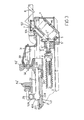
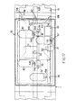
- the Fig. 1 shows a plan view of a so-called english type point with a switch box according to the invention.
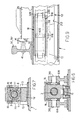
- the Fig. 2 shows a cross-section according to a vertical plane transversal to the track of a switch box according to the Fig. 1 .
- the Fig. 3 shows an enlarged detail of the cross-section according to the vertical plane of Fig. 1 , in the area of one blade and one rail.
- Fig.s 4 and 5 show a detail relating to the drive slide and to the movable locking means of the same, in the locked and unlocked position respectively before the start of the translation.
- Fig.s 6 and 7 show two transversal cross-sections of the saddle and of the movable locking means according to Fig. 4 , according to the line VI-VI and VII-VII respectively.
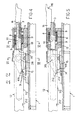
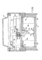
- the Fig. 8 shows an enlarged plan view on the transmission rod-carrying slide in the closed position of translation with the guide integral with the drive slide.
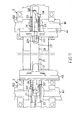
- the Fig. 9 shows an enlarged lateral cross-section in elevation of the rod-carrying saddle and of the drive slide.
- the Fig. 10 shows a lateral cross-section of the rod carrying saddle and of the drive slide.
- the Fig. 11 shows an enlarged partial view of the switch according to Fig. 1 in which only the area of the two external blades and the locking means relative to the same can be seen.
- Fig.s 12 to 14 show some phases of disengagment of the drive slide and the rod-carrying saddle in kicking condition and/or of impediment of the blade upon reaching the correct position of closure.
- Fig.s 15 and 16 show the locking means of the rails to the switch box.
- Fig.s 17 to 20 show different views and different cross-sections of the box for the blade position sensors, of the rod-carrying saddle and of the drive slide and the means for transforming the switch box from kicker to non-kicker.
- a so-called english switch is shown, of the type foreseen in correspondence to crossings and with four blades.
- the english type swich two tracks are provided with the rails B1, B1' and B2, B2' which co-operate with the blades A1,A1' and A2, A2' respectively.
- a box 1 with shape and dimensions corresponding substantially to those of a sleeper, are housed the means for shifting the blades A1, A1' and A2, A2'.
- the switch box 1 in the shape of a sleeper has laterally widening fins 101 ( Fig.s 15 and 16 ) which engage with the rail clips 2 of the rails B1, B1', B2, B2'.
- one or both surfaces of contact facing each other of the rail clip 2 and of the fins 101 can have teeth, or better a knurling parallel to the longitudinal axis of the track. This allows to obtain both a better registration of the relative position of the two parts, as well as a better clamping with regards to a relative translation between fin and rail clip 2.
- the switch box 21 in the shape of a sleeper extends itself for a certain length also outside the track substantially in a dimension corresponding to the sleepers and in one of said external extentions of the extremities is housed a drive motor generally of the electrical type indicated with M.
- the motor M activates by rotation by means of a bevel gear 5, 5' transmission a threaded rod 3 which is connected to the output shaft 5" of the transmission by means of a coupling 4 which can be of any type also of the type that disengage under condition of stress greater than a preset torque or clutch type.
- a crank 6 with a shaft 106 at the end of which a bevel gear 206 is provided that engages with a bevel gear 5''' it also revolving together with the output shaft 5" of the transmission which is coaxial the bevel gear 5' connected to the motor.
- the two bevel gears 5' 5''' are coaxial and have different diameters to ensure the appropriate transmission ratios suitable for driving with the motor M and for manual drive with the crank 6.
- the crank 6 can be inserted into position of engagement with the bevel gear 5''' of the transmission through an opening 7 in shape of a revolving support sleeve of the box 1 equipped with a lid 107.
- a Nut screw 8 is inserted on the threaded rod 3 which is housed in a manner to move freely axially between two opposite end of stroke stops 9 which are provided at the extremity on a first drive slide 12.
- the drive slide 12 can slide in the two directions in the longitudinal sense of the threaded rod 3 on the bottom of the box 1 thanks to the wheels 13.
- the nut screw 8 is connected in a reciprocally non revolving manner and translatable together thanks to a radial key 10 to a slide 11 which is therefore movable relative to the drive slide 12 between the two end of stroke stop walls 9 ( Fig.s 7 , 8 ).
- the free travel of the nut screw 8 between the two end of stroke stops 9 is inferior to the global travel necessary to shift the blades between the two positions of closure of the blades A1, A2 and A1' and A2' respectively to the corresponding rail. Therefore at the start of each phase of activation of the switch, the nut screw 8 and the slide 11 carry out a certain idle travel. This travel is used to activate in sense of disengagement the locking means of a first drive slide 12.
- the drive slide 12 is provided with wheels 13 and has in the middle area o bottom recess 112 provided with two notches 212 engaging a locking tooth 14.
- the locking tooth is supported by spring loaded means 15 which push it firmly in position of engagement in the notches 212 and protrudes out of at least one lateral side of the slide 12 at least in the area of the notches 212, preferably of both sides of the drive slide 12.
- the slide 11 has in a position protruding from the lateral sides of the same respectively one roller 111 of a pair of coaxial rollers.
- the rollers 111 engage with cam tracks 116 realized by appropriate profiling of an longitudinal end edge in the example the lower one of the two levers 16 oscillating between themselves perfectly aligned, coincident and symmetric and which are fulcrated on the same shaft 316 which is supported by two stationary elements 616 placed on the two sides of the drive slide 12 and between which the said slide can freely pass during its travel.
- the two oscillating levers 16 extend themselves beyond the fulcrum shaft 316 towards the middle area of the drive slide 12.
- the two oscillating levers 16 extend themselves along the two sides of the slide 12 up to the area of the slide 11 and the nut screw 8.
- the oscillating levers terminate with a pressure head 416 which engages with the section of the locking tooth 14 of the drive slide 12 protruding out of the sides of the same.
- Fig.s 4 and 5 show the starting phase of the travel unlocking the drive slide 12 by the nut screw 8 and the slide 11.
- the slide has reached the end of stroke position corresponding to a motion to the left in direction of the arrow F1.
- the reversal of the direction of displacement of the slide indicated with F2 causes a first idle travel of the nut screw 8 and of the slide 11 until they come to a stop against the wall 9.
- the end of stroke positions of the drive slide 12 are defined by a stationary stop 60 integral with the bottom of the box and through which passes an axial extension 412 of the slide 12 which has an enlarged striker 512 on the extension at its free extremity.
- a stationary stop 60 integral with the bottom of the box and through which passes an axial extension 412 of the slide 12 which has an enlarged striker 512 on the extension at its free extremity.
- one of the two faces of the end of stroke stop 6 comes into contact with the enlarged striker 512 on the extension 412 and the front end of the slide 12 respectively on which said extension is fitted.
- the rod-carrying saddle 18 is of tubular construction, and the side walls of the same have a plan form in shape of isosceles trapezoids, forming at the opposite ends of each side wall 318 of the rod-carrying saddle 18 inclined surfaces 518 in a direction simmetrically opposed to each other and converging towards the central area of the very slide 18.
- the rod carrying saddle 18 has on the bottom and on the top side, a double slide guide respectively, that is on both sides or one side 418 for instance longitudinal central grooves, or half of the same, in which the extremities of a central rod 120 are housed.
- the central rod 120 is connected to the rod-carrying saddle 18 thanks to a pair of carriage springs 220.
- Each of the two carriage springs is connected with the extrados side and in a simmetrical position with regards to the other carriage spring to the central rod 120, whereby the plan seen from above has substantially the shape of an "X", cut vertically in half by the rod 120.
- Each of the free extremities of the carriage springs 220 has a roller 320.
- each roller 320 engages with an inclined surface 518 of the rod-carrying saddle 18.
- the rollers 320 at the extremities of each carriage spring 220 engage for each carriage spring respectively with the inclined surfaces 518 on the end sides of the very side of the rod-carrying saddle 18 towards which the carriage spring is faced.
- the central rod 120 is fixed to the carraige springs 220, substantially at one single point, in particular in correspondence of the point or more precisely of the tangential band of the carriage springs 220 to said rod 120 by means of a locking clamp 420.
- the central rod 120 connects at both its extremities thanks to the joints 22 with the transmission rods 21 which extend themselves up to the area underneath the corresponding rail B1, B1', B2, B2'.
- the extremity 121 of the transmission rods is in shape of a plate, in the horizontal example and slides between two lateral guide walls 23.
- a first elongated slot 221 is made in the top face which has a certain preset length and is foreseen closer to the coupling 22 to the central rod 120 of the rod-carrying saddle 18 and at a preset distance from this first groove 221, in the end area a second angular elongated slot 321.
- the first slot 221 is rectilinear and the axis of the same is parallel and coincident with the central longitudinal axis of the corresponding transmission rod 21.
- the second slot 321 forms an obtuse angle and has a branch parallel to the central, longitudinal axis of the corresponding transmission rod 21, but laterally offset relative to the latter, substantially in a measure corresponding to the length of the tooth 124 of an oscillating lever 24, and a transversal, inclined branch which substantially terminates in correspondence to the central area of the transmission rod 21.
- the length of projection of the second slot 321 on the longitudinal axis of the corresponding transmission rod 21 is substantially identical to the total length of the first slot 221.
- each transmission rod 21 On the extremity 121 of each transmission rod 21 rests an oscillating lever 24 which is angled at its extremity in correspondence to the free extremity of the transmission rod 21in order to form a coupling tooth 124. From the lower rest surface of the oscillating lever 24 depart in a position coinciding with the slots 221 and 321 two transversal pins 224 and 324 which engage in the corresponding slots 221 and 321 of the extremities 121 of the transmission rods 21.
- a pin 224 is provided in correspondence of the extremity of the oscillating levers 24 facing the rod-carrying slide 18, while the other pin 324 is provided in an aligned position with the first 224, with reference to the longitudinal axis of the longer branch of the oscillating levers 24 and in the area of the angle of the same.
- the distance between the two pins 224 and 324 is substantially corresponding to the distance of the projections on the longitudinal axis of transmission rods 21 of the extremities, on the same side, of the slots 221 and 321, in such a way, that when the pin 224 stops against one of the extremities of the slot 221, the pin 324 stops against the end on the same side of the angled slot 321 which in this case has the function of a guide track of the pin 324 and determines an angular displacement in the horizontal plane of the oscillating lever 24, whose travel is sufficient to bring the lever alternately into position of engagement of the tooth 124 on the front end of the facing wall of the lateral guide 23 and in the position of disengagement of the same thanks to a relative displacement between transfer rod and oscillating lever 24.
- each oscillating lever In coaxial position to the locking pin 224 in the rectilinear slot 221 of the transmission rod 21, from the top side of each oscillating lever departs a tansversal extension connected to the point which is formed by a bolt 424 with a head 524 in form of a spherical joint seat for a ball joint type appendix 25 integral with the blade A1, A1', A2, A2', in such a way, that the oscillating lever 24 is coupled with the corresponding blade A1, A1', A2, A2, in a revolving manner at least around the common axis with the pin 224 of the very lever 24.
- the spherical appendix 25 departs from a small arm 125 fixed on the blade A1, A1', A2, A2', in particular to the longitudinal lateral surface of the same.
- the pins 224 and 324 of the oscillating levers 24 coupling with the blades initially closed stop against the extremity of the associated slots 221, 321 on the side of the same in front with regards to the direction of translation of the transmission rods 21. Therefore, in an initial phase of the travel of translation of the transmission rods 21, the transmission rod 21 associated with the closed blade in the start-up position carries out a relative motion with regards to the very blade and to the coupling oscillating lever 24.
- the relative motion is such as to bring the lever 24 associated with the blade in position of closure in the start-up condition, into position of disengagement from the edge of the lateral guide wall 3, while on the opposite side, the guide rod has executed a relative motion such, that the oscillating lever 24 associated with one or more blades which have to be brought into position of closure assumes a slightly inclined position and substantially of rest against the internal surface of the side wall of the guide 23 associated with it.
- the pins 324 of all oscillating levers 24 connected to the corresponding blades A1, A1' have reached substantially an intermediate position between the extremity of the inclined branch and the extremity of the same in the angle area of the corresponding slots 321.
- the oscillating levers 24 are retained in this position by effect of the lateral guides 23 against which they slide in their further travel during which , the arms 24 and with them the blades are driven together with the transmission rods 21.
- the blade reaches the position of closure and at the same time the tooth 124 of the coupling oscillating lever 24 passes beyond the rear edge of the facing side wall of the guide 23, with reference to the direction of translation of the transmission rods 21, whereby the further translation of the transmission rods 21 determins the subsequent oscillation, especially of the oscillating lever 24 associated with the blade that has been brought into position of closure, into the position of engagement behind the facing front edge of the lateral guide walls.
- the oscillating lever of the blade that passed into the position of moving away from the associated rail is subsequently brought into a central position with regards to the lateral guides 23.
- the rollers 111 of the slide 1 associated with the nut screw 8 reach a new recessed part of the control cam 216 obtained thanks to the profiling of the oscillating levers 16 which are supported stationary on a lateral support 616 through which passes the drive slide 12, so that the locking tooth 14 of the drive slide 12 penetrates into the corresponding notch 212 of the same, locking it in the position of closure it just reached.
- the particular construction of the rod-carrying saddle 18 makes the switch a kicker type. This means, that the switch can be activated by a train suddenly arriving from an opposite direction to the arrow T in Fig. 1 and from the incorrect track, will act with the wheel on the unlocked blade.
- the wheel of the train exerts a force of displacement in direction of closure of the blade not locked to its associated rail and if the blade of the switch should not yield this would entail braking the same or in any case a derailment.
- the inclined planes have a length such, that the sliding of the rollers from one extremity to the other of the same corresponds substantially to the length of the section of the angled slots 321 of the transmission rods that is rectilinear and parallel to the longitudinal axis of the transmission rods so that as evidenced in Fig. 13 , as long as the rollers remain on the inclined planes 518 and do not reach the intermediate zone of the lateral walls of the rod-carrying saddle 18, the oscillating levers 24 with the locked blades -do not pass into a position of disengagement.
- This allows the mechanism of transmission to absorb slight mechanical stresses exercised on the blades, without causing the abandonment of the switch position.
- the rod-carrying saddle 18 integral with the drive slide 12 allows to avoid stresses on the drive motor in case mechanical obstacles come between the blade and the corresponding rail during the closing phase.
- the drive slide can in any case be brought into the position of end of stroke, with a disengagement of the central rod 120 of the rod-carrying saddle 18 analogous to the one described in the phase of kicking.
- the switch box has sensors for the position of the blades, of the central rod 120 and the drive slide 12.
- the position sensors consist of limit switches 30 housed in small boxes 31 which adhere to outside the of the rail.
- the switches 30 are activated by a small rod 32 that passes transversly through the rails , protruding on the inside of the same against which acts the side of the blade facing it.
- Fig.s 17 and 19 show hybrid forms of execution of a small box 35 in that in combination with each other all the functionalities are provided whether for the English type switch or for the normal switch.
- the means illustrated with reference to the Fig.s 17 and 19 can be distributed on said two small boxes.
- a slider 37 that is carried by the rod-carrying saddle, tubular 18 and integral with the drive slide 12.
- the slot 36 has a length corresponding substantially to the travel of the drive slide and is oriented in direction of translation of the same.
- the slider 37 co-operates with two limit switches 38 and 38' which are located at the end sections of the slot 36 at a distance and in a position corresponding to the stroke of the drive slide 12 and to the end of stroke positions of the same.
- the slider 37 acts thanks to inclined lead-in surfaces 137 on the trip buttons 138 of the switches.
- the position sensors of the central rod 120 are made in a similar manner.
- a slot 36 oriented in direction of translation of the transmission rods 21 and of a length corresponding to the stroke of the same is provided in the bottom of the small box 35 coincident with the central rods 120.
- Through the slot 36 protrudes in the interior of the small box a small segment of the rack 39 which engages with toothed rollers 140 associated with each of the two limit switches 40 arranged at appropriate distances and in appropraite positions analogous to what described for the drive slide 12 in the section of the extremities of the slot 36.
- the toothed rollers have an axial tooth 240 on the side facing the switches 40 this tooth extending itself over a certain angular amplitude and connects with inclined sides 340 with the remaining section of the front edge of the roller 140.
- the axial tooth 240 trips the pushbutton of the switch 40 and according to the position of the roller determined by the rack, the pushbutton 440 will be depressed or not.
- the passage of the rack over the toothed rollers determines therefore the signal of position of the central rod 120.
- the central small box relating to a normal switch has the same identical sensors for the drive slide 12 and for the central rod 120.
- a small activating rod 41 is foreseen analogous to the one for the outside rail A1, A2' and which passes from side to side through the associated rail B1'. B2.
- the protruding extremity at the side of the opposite rail acts thanks to a pressure plate 141 on a further small rod 42 which is supported sliding in the wall of the small box 35 and which protrudes on the inside of the same, where it acts against an intermediate point of a transversal oscillating lever 43, the free extremity of which acts in a manner of compression on the pushbutton tripping the limit switch 50.
- the small box 35 foreseen in the english type switch can only house the position sensor of the second internal blade A1', which is realized analogous to what described in the preceding paragraph, or rather it also can house position sensors for the drive slide 12 and the central slide 120 realized analogous to the one previously described, where in this case the slider 37 and the rack 38 are associated with other parts integral with the drive slide 12 and the central rod 120.
- the pin 50 engages with slots 52 in the central rod 120, whose length is such to allow within preset limits a certain relative motion between the central rod 120 and the rod-carrying saddle 18. This in particular to allow the rod-carrying saddle 18 and the drive slide 12 to always reach the end of stroke position where the motor M is deactivated also in the case when obstacles are found between the blade and the closure rail of the same which prevent the blade from locking in the end of stroke position against the rail.
- the slots 52 have such a length, that the relative travel between the central rod and the saddle which in the case indicated above takes place against the action of the carriage springs 220 keep the rollers of the carriage springs always within the range of the inclined planes 518 of the rod-carrying saddle 18. Therefore, the central rod can carry out small relative motions with regards to the rod-carrying saddle 18 and to the drive slide 12, but can never be disengaged as in the case of the Fig. 14 when the switch is of the kicker type.
- the pin 50 can simply be engaged or alternatively engaged and disengaged on command thanks to the electromagnet 51.
- meccanical means are provided which bring the pin 50 automatically in the inactive position upon activation of the switch.
- lifting means are provided associated with the rod-carrying saddle 18 and said means consist of inclined planes 154 of a cam track 54 that co-operate with a roller 53 supported in a revolving manner around an axis transversal to the direction of sliding of the central rod 120 and laterally offset in an aligned position with said inclined planes 154 at the free extremity of the pin 50.
Landscapes
- Mechanical Engineering (AREA)
- Engineering & Computer Science (AREA)
- Train Traffic Observation, Control, And Security (AREA)
- Railway Tracks (AREA)
- Near-Field Transmission Systems (AREA)
- Electric Propulsion And Braking For Vehicles (AREA)
- Contacts (AREA)
- Devices For Checking Fares Or Tickets At Control Points (AREA)
- Valves And Accessory Devices For Braking Systems (AREA)
- Tumbler Switches (AREA)
- Transition And Organic Metals Composition Catalysts For Addition Polymerization (AREA)
- Switch Cases, Indication, And Locking (AREA)
- Measuring Magnetic Variables (AREA)
- Power-Operated Mechanisms For Wings (AREA)
- Slide Switches (AREA)
- Metal Rolling (AREA)
- Mechanisms For Operating Contacts (AREA)
- Knitting Machines (AREA)
Claims (41)
- Boîtier de manoeuvre pour lames d'aiguillages de chemin de fer, tramway ou analogue, comprenant une unité de transmission ( M, 3, 4, 5, 5', 5", 5"', 6 ) pour le mouvement de transfert des lames ( A1, A1', A2, A2') de l'aiguillage, au moins un groupe (12, 18, 120, 21, 24 ) pour la transmission linéaire du mouvement de transmission aux lames, et des moyens mobiles ( 24, 124 ) pour bloquer les lames dans leur position respective de fermeture, l'unité de transmission, ledit groupe et les moyens mobiles étant logés dans un boîtier (1) qui a en grande partie les dimensions et la forme d'une traverse et qui est destiné à être posé sur la voie ferrée à la place de et avec la fonction d'une traverse,
caractérisé en ce que
lesdits moyens mobiles (23, 24, 124 ) pour bloquer les lames (A1, A1', A2, A2' ) dans leur position respective de fermeture sont couplés avec leur lame respective (A1, A2' ), sont disposés à l'intérieur du boîtier (1) dans la région de la lame (A1, A2' ) elle-même et sont amenés automatiquement dans une position de blocage actif sur la lame correspondante (A1, A2' ) atteignant la position de fermeture, tandis qu'ils sont automatiquement débrayés au moment où le boîtier de manoeuvre pour lames d' aiguillages est activé pour transférer la lame vers la position de fermeture avec la lame opposée (A2', A1),
lesdits moyens mobiles pour bloquer les lames comportent des leviers (24) au moins pour coupler les lames les plus à l'extérieur (A1, A2') à une tige de transmission (21) pour le mouvement de transmission des lames,
lesdits leviers (24) oscillent dans le plan horizontal,
lesdits leviers (24) ont une dent latérale (124) à l'extrémité opposée à leur point d'appui, laquelle est mis en prise avec des butoirs fixes (23) dans la région des lames (A1,A2'),
lesdits leviers (24) s'étendent au-delà des lames (A1,A2') en direction du rail associé (B1,B2'),
et lesdits leviers (24) et les butoirs fixes (23) s'étendent dans une région en-dessous du rail correspondant (B1,B1',B2,B2'). - Boîtier de manoeuvre pour lames d'aiguillages selon la revendication 1, caractérisé par le fait qu'il possède des moyens linéaires (12) pour la transmission, consistant en un chariot, ou une coulisse, qui est déplacé de manière transversale à la voie ferrée, en particulier de manière orthogonale à celle-ci, dans les deux directions entre deux positions extrêmes de fin de mouvement par un groupe ( M, 3, 4, 5, 5', 5", 5"', 6) pour transformer le mouvement de rotation en mouvement linéaire et auquel est couplé une tige de transmission (21) pour une ou plusieurs lames (A1, Al', A2, A2') tandis qu'une lame (A1, A2' ) est reliée au levier (24) qui la couple à la tige de transmission respective (21) grâce à des moyens mobiles correspondants (21, 121 321, 23, 124, 224, 324).
- Boîtier de manoeuvre pour lames d'aiguillages selon la revendication 2, caractérisé par le fait que les tiges de transmission (21) pour le mouvement de transmission des lames ( A1, A1', A2, A2' ) sont supportées par au moins une coulisse de transmission (12), et des moyens mobiles de blocage de la coulisse de transmission (8, 9, 11, 15, 16, 216, 212 ) étant prévus aux deux positions extrêmes de fin de course de la coulisse de transmission (12) en supplément des butoirs de fin de course ( 60, 412, 512).
- Boîtier de manoeuvre pour lames d'aiguillages selon la revendication 3, caractérisé par le fait que les tiges de transmission (21) peuvent être libérées de la contrainte mécanique de liaison avec la coulisse de transmission (12) par l'action d'une force extérieure de déplacement exercée sur les lames (A1, A1', A2, A2').
- Boîtier de manoeuvre pour lames d'aiguillages selon la revendication 3, caractérisé par le fait que des détecteurs automatiques de fin de course (3, 31, 32, 35, 36, 37, 38, 39, 40 ) sont prévus pour chacune des lames (A1, A1', A2, A2' ), pour les tiges de transmission (20, 21) et pour la coulisse de transmission (12).
- Boîtier de manoeuvre pour lames d'aiguillages selon la revendication 2, caractérisé par le fait que chaque levier (24) est relié à la lame correspondante (A1, A2') au moyen d'un joint ( 424, 525, 25 ) qui permet la rotation des leviers autour d'un axe perpendiculaire, de préférence au moyen d'un joint à rotule, des moyens (224, 324, 221, 321) étant prévus entre chaque levier de couplage et la tige de transmission (21) afin de contrôler la position angulaire du même levier de couplage (24) de telle sorte que, pendant l'activation de l'aiguillage, les leviers de couplage (24), ou tout au moins le levier de couplage (24) engagé avec la lame (Ai) en position de fermeture dans la situation de mise en route, sont amenés en position de débrayage par les butoirs fixes de mise en prise (23), avant que la translation des lames (A1, A1', A2, A2' ) ait lieu et lorsque l'une des deux lames (2') atteint la position de fermeture, le levier de couplage correspondant (24) est déplacé angulairement vers la position de mise en prise de la dent terminale (124) derrière le butoir fixe (23) par rapport à la direction de déplacement de la lame (A1) fermée en position d'éloignement de son rail associé ( B1).
- Boîtier de manoeuvre pour lames d'aiguillages selon la revendication 6, caractérisé par le fait que les moyens de contrôle du mouvement angulaire des leviers de couplage sont constitués de rainures ou de cannelures façonnées (321) qui forment des trajectoires de contrôle construites dans tes tiges de transmission ( 21, 121 ) et qui mettent en prise au moins un appendice (324 ) faisant saillie à partir du côté faisant face des leviers de couplage (24).
- Boîtier de manoeuvre pour lames d'aiguillages selon la revendication 6, caractérisé par le fait que l'axe d'oscillation des leviers de couplage (24) est prévu dans la zone des moyens le reliant à la lame correspondante (A1, A2' ) tandis que le levier de couplage (24) s'étend lui-même au-delà de la lame (A1, A2' ) en direction du rail associé ( B1, B2' ) à l'intérieur de guides latéraux (23) orientés dans la direction de mouvement des tiges de transmission (21 ) et tandis que ladite tige est en grande partie verticale et que les leviers de couplage s'appuient sur les extrémités associées des tiges de transmission (21 ).
- Boîtier de manoeuvre pour lames d'aiguillages selon la revendication 6, caractérisé par le fait que les leviers de couplage (24) sont mis en mouvement alternativement à partir de la position de mise en prise avec les butoirs fixes (23) vers la position de débrayage, grâce à un mouvement relatif des tiges de transmission (21) par rapport à ceux-ci, en particulier dans une partie initiale ou terminale du mouvement commandant les dites tiges de transmission (21).
- Boîtier de manoeuvre pour lames d'aiguillages selon une ou plusieurs des revendications précédentes, caractérisé par la combinaison de traits suivante:- les tiges de transmission (21) ont une cannelure courbée (321) dans laquelle est mise en prise de manière mobile au moins une goupille de commande (324) du levier de couplage correspondant (24);- chaque rainure ou cannelure courbée (321) a une section parallèle à l'axe longitudinal moyen des tiges de transmission (21) et qui est disposée latéralement en compensation le long du côté du dit axe longitudinal moyen, et ladite section s'étend en direction de l'extrémité libre avec une section inclinée qui se termine en grande partie dans la zone de l'axe longitudinal moyen des tiges de transmission (21), ou en tout cas dans une zone intermédiaire de la dimension transversale des dites tiges de transmission (21);- des moyens d'arrêt (23) avec lesquels est mise en prise la dent latérale (124) des leviers de couplage (24);- des moyens (23) limitant l'oscillation dans la direction de mise en prise avec les butoirs associés (23) des leviers de couplage (24),- dans la partie du mouvement où les leviers de couplage (24) sont entraînés par les tiges de transmission (21);- la position et la forme de la rainure ( 324 ), aussi bien que la projection de la dent (124) des leviers de transmission (24), et la conformation et la position des moyens (230 ) de mise en prise de la dent latérale (124 ) des leviers de couplage (24) et des moyens (23) limitant l'oscillation pendant le mouvement de commande, étant dimensionnés et disposés de manière telle que, dans la partie initiale du mouvement de commande, les tiges de transmission (21) se déplacent par rapport aux leviers de couplage (24) aussi longtemps que le levier de couplage (24) qui est dans la position de mise en prise, étant relié à ta lame (A1 ) fermée en position de mise en route, est amené en position de débrayage par le butoir (23), tandis que le levier (24) en position de désengagement, étant relié avec la lame qui doit être prise dans la position de fermeture ( A2' ), est limité dans son déplacement angulaire par lesdits moyens de limitation (23) de manière telle que l'appendice ( 324 ) se projetant à partir desdits leviers de couplage (24) dans la zone de la dent (124 ) et mis en prise dans la rainure courbée ( 321 ), se positionne â un point intermédiaire de la section inclinée des dites rainures ou cannelures ( 321 ), de sorte que la paroi inclinée de chaque rainure ( 321 ), tournée dans la direction du mouvement des lames (A1, A2'), devienne, grâce à ta limitation de l'oscillation du levier de couplage ( 24 ), reliée à la lame (A2') qui doit être amenée en position de fermeture par les guides latéraux, la surface de mise en prise pour commander le même levier de couplage correspondant ( 24) avec la tige (21) et lorsqu' il est en position de fermeture de la lame (A2'), le levier de couplage (24) est libéré des moyens ( 23 ) limitant le mouvement angulaire et continue à osciller, étant amené en position de mise en prise avec le butoir fixe correspondant ( 23).
- Boîtier de manoeuvre pour lames d'aiguillages selon la revendication 10 caractérisé par le fait que les moyens limitant l'oscillation des leviers de couplage ( 24 ) et les butoirs de mise en prise de la dent (124 ) des leviers de couplage ( 24) sont constitués les premiers par l'assemblage de parois de guidage latéral (23 ) des tiges de transmission (21) et des leviers de couplage ( 24), lesdites parois (23 ) étant disposées à une distance prédéterminée l'une de l'autre, et les seconds par les côtés extrêmes opposés aux lignes centrales de la trajectoire de rune desdites parois de guidage latéral ( 23 ), lesdits côtés extrêmes étant disposés dans une position telle que, lorsque la dent ( 124 ) des leviers de coupage ( 24 ) les a tout juste dépassés, la lame (A2) est en position de fermeture, tandis que a paroi de guidage latéral (23 ) faisant face dans a direction de a dent latérale ( 124 ) du levier de couplage correspondant ( 24 ) constitue une paroi coulissante et limitante dans la position où l'appendice (324 ) du levier de couplage ( 24) est en grande partie positionnée dans la zone centrale de la branche inclinée de la rainure de transmission correspondante ( 324 ) dans la tige de transmission (21).
- Boîtier de manoeuvre pour lames d'aiguillages selon une ou plusieurs des revendications précédentes, caractérisé par le fait que chaque tige de transmission (21 ) possède une seconde rainure ( 221 ) en grande partie parallèle à et coïncidente avec l'axe longitudinal moyen et dans laquelle est logée une goupille ( 224 ) du levier de couplage correspondant ( 24 ) ou similaire qui est mobile le long de la rainure ou cannelure rectiligne ( 221 ) et qui par rapport au déplacement angulaire du levier de couplage ( 24 ) est coaxial aux moyens ( 424, 524, 25 ) couplant le levier ( 24 ) à la lame (A1, A2'), par exemple à au moins un joint d' un type rotatif.
- Boîtier de manoeuvre pour lames d'aiguillages selon une ou plusieurs des revendications précédentes, caractérisé par le fait que les tiges de transmission ( 21 ) sont reliées (1201 220, 320, 518 ) à un chariot support de tige commun (18 ) supporté de manière mobile en grande partie dans une direction orthogonale à l'axe de la trajectoire, ledit chariot support de tige (18 ) est relié de façon permanente à une cou tisse de transmission (12), tandis que les tiges de transmission ( 21) sont couplées au chariot support de tige ( 18 ) par des moyens de couplage mobiles ( 220, 320, 218, 518 ) qui passent en position de débrayage de celui-ci et de la coulisse de transmission (12 ) quand ta résistance à la translation des lames (A1, A1' , A2, A2' ) dépasse un certain moment de torsion prédéterminé, ou bien quand une force est appliquée dans la direction du mouvement directement sur les lames (A1, A1', A2, A2'), de sorte que les mêmes tiges de transmission (21) sont translatées par rapport au chariot support de tige ( 18 ) d'un moment de torsion prédéterminé couplant celui-ci au chariot support de tige (18).
- Boîtier de manoeuvre pour lames d'aiguillages selon la revendication 14, caractérisé par le fait que tes tiges de transmission (21) sont couplées au chariot support de tige (18 ) au moyen d une tige centrale (120 ) qui possède des rouleaux (320 ) tournant dans la direction de coulissement de celle-ci, les tiges de transmission (21) sont supportées de manière chargée par ressort ( 220 ) de façon mobile transversalement à la direction de coulissement des tiges de transmission ( 21 ) contre une force prédéterminée chargée par ressort, tandis que chaque rouleau (320) est en prise avec un plan incliné (518), ménagé dans les parois ondulées (218 ) sur le chariot support de tige (18), deux plans inclinés (518) étant prévus, par rapport à la direction de coulissement du chariot support de tige (18 ) et avec des inclinaisons symétriquement opposées l'une à l'autre sur chacune des deux parois ondulées opposées ( 218) pour les rouleaux (320), pour chaque plan incliné ( 518 ) étant prévu au moins un rouleau correspondant ( 320) relié aux tiges de transmission (21) et à une tige de couplage centrale commune ( 210).
- Boîtier de manoeuvre pour lames d'aiguillages selon les revendications 4 ou 14, caractérisé par le fait que le chariot support de tige (18 ) est montée sur un guide supérieur (19) de la coulisse de transmission (12) et possède deux parois latérales opposées orientées dans la direction de coulissement des tiges de transmission (21 ) sur les parois desquelles sont prévues deux projections (218) en forme de trapézoïde isocèle qui se font face et sont coïncidentes entre elles et dont les côtés inclinés forment les plans inclinés (518) s'engageant avec les rouleaux ( 320) de la tige centrale (120 ) aux deux extrémités opposées de laquelle sont reliées deux tiges de transmission ( 21 ).
- Boîtier de manoeuvre pour lames d'aiguillages selon une ou plusieurs des revendications précédentes 13 à 15, caractérisé par le fait que la tige centrale de couplage aux tiges de transmission (21) possède deux rouleaux ( 320 ) pour chaque paroi ondulée du chariot porteur de tige (18), lesdits rouleaux (320) sont supportés aux extrémités respective ment par un ressort de voiture (220 ) et les deux ressorts de voiture (220) étant fixés l'un à l'autre, sur les deux côtés longitudinaux de la tige centrale de liaison (120) en correspondance avec les côtés externes desdits ressorts (220) et la longueur des ressorts de voiture (220) étant telle qu'en condition de mise en prise de la tige centrale (120) avec le chariot porteur de tige (18) et la coulisse de transmission (12) les rouleaux sont prévus à l'extrémité la plus extrême du plan incliné correspondant ( 518).
- Boîtier de manoeuvre pour lames d'aiguillages selon une ou plusieurs des revendications précédentes caractérisé par le fait que des moyens de verrouillage mobile ( 3, 8, 9, 10, 11, 12, 212, 14, 15, 16 ) sont prévus pour la coulisse de transmission ( 12 ) aux deux positions de fin de course de fermeture de l'une ou l'autre lame (A1, A1', A2, A2').
- Boîtier de manoeuvre pour lames d'aiguillages selon la revendication 17, caractérisé par le fait que les dits moyens de verrouillage mobile de la coulisse de transmission consistent en des moyens oscillants (16) pour le désengagement d'une dent de blocage (14) pressée élastiquement de manière stable ( 15 ) en direction de mise en prise dans une ou plusieurs encoches (212 ) distribuées le long d'un côté longitudinal de la coulisse de transmission (12).
- Boîtier de manoeuvre pour lames d'aiguillages selon la revendication 17 ou 18, caractérisé par le fait que les moyens pour désengager la coulisse de transmission (12) des moyens de blocage (14) dans la position de fin de course de la coulisse sont directement contrôlés par les moyens (3, 8, 9 ) couplant la coulisse de transmission (12 ) au dispositif de commande de transmission linéaire ( 3,8 ), pendant une période du mouvement dans laquelle les moyens (8,9) couplant les dispositifs de commande linéaire ( 3, 8 ) effectuent un mouvement relatif à vide par rapport à la coulisse de transmission (12), avant d'atteindre le point d'engagement mécanique de transmission ou de poussée avec ladite coulisse de transmission (12), lesdits moyens pour coupler les commandes linéaires à la coulisse de transmission (12 ) étant munis de moyens de contrôle (11, 111 ) du levier d' oscillation (16 ), tandis que les moyens pour engager la dent de blocage ( 14 ) dans l'encoche correspondante (212 ) de la même coulisse de transmission (12 ) sont constitués par les moyens de couplage (8, 9, 1, 111), qui pendant la période finale du mouvement de commande se déplacent en même temps que ladite coulisse de transmission (12).
- Boîtier de manoeuvre pour lames d'aiguillages selon une ou plusieurs des revendications précédentes 18 à 20, caractérisé par le fait qu'il est prévu un balancier à coulisse, constitué par au moins un levier ( 16 ) oscillant autour d'un axe (316 ) transversal à la course de la coulisse de transmission ( 12 ) et qui s'étend lui-même parallèlement à ladite course, ledit axe ( 316) d'oscillation étant fixe par rapport à la coulisse de transmission (12), formant à une extrémité du levier d'oscillation un moyen de pression sur la dent de blocage ( 14 ) de la coulisse de transmission (12 ) pour déplacer celle-ci alternativement vers une position d'embrayage et une position de débrayage de l'une des encoches (212) dans les parois coopérantes de la coulisse de transmission (12), tandis que l'autre partie du levier d'oscillation, sur le côté opposé de l'axe du point d'appui ( 316), a la forme d une came de contrôle (216) qui est en prise avec au moins un rouleau (111 ) mobile avec les dits moyens ( 8, 9 ) couplant la coulisse de transmission (12 ) au dispositif de commande linéaire.
- Boîtier de manoeuvre pour lames d'aiguillages selon une ou plusieurs des revendications précédentes 17 à 20, caractérisé par le fait que les moyens couplant la coulisse de transmission ( 12 ) au dispositif de commande linéaire sont constitués par une pièce à coulisse (8, 10, 11) qui peut coulisser entre deux butoirs opposés de fin de course ( 103 ) espacés l'un de l'autre d'une distance correspondant au roulement à vide nécessaire pour amener le levier oscillant (16 ) vers la position de mise en prise et de désengagement de la dent de blocage (14) avec l'une des encoches ( 212 ) dans la coulisse de transmission (12) correspondant à la position de fin de course de celle-ci, ladite pièce à coulisse ( 8, 10, 11 ) est reliée dynamiquement au dispositif de commande linéaire ( 3, 8 ) et possède au moins un rouleau (111 ) en prise avec la trajectoire de la came ( 116 ) profilée sur la branche correspondante du levier oscillant (16).
- Boîtier de manoeuvre pour lames d'aiguillages selon la revendication 20, caractérisé par le fait que le balancier à coulisse est constitué de deux leviers ( 16 ) coïncidant et se complétant l'un l'autre, dont chacun s'étend lui-même le long des côtés longitudinaux latéraux de la coulisse de transmission (12), lesdits leviers oscillants (16 ) étant appuyés sur le même axe ( 316 ) en rotation dans des supports latéraux (616) et faisant du balancier à coulisse une structure du type pont à travers laquelle et sous laquelle passe au moins une partie de la coulisse de transmission (12 ) d'une longueur correspondant en grande partie au mouvement de commande de celle-ci, tandis que le balancier à coulisse (8, 10, 11) associé au dispositif de commande linéaire (3, 8) possède un rouleau (111) pour chaque levier (16 ) du balancier à coulisse et est mobile entre deux parois (9 ) de fin de course qui sont transversales au mouvement de la coulisse de transmission ( 12 ), se faisant face et espacés l'un de l'autre d'une distance correspondant au mouvement des rouleaux de contrôle ( 111 ) pour débrayer la coulisse de transmission (12) de la dent de blocage (14).
- Boîtier de manoeuvre pour lames d'aiguillages selon la revendication 20, caractérisé par le fait que les rails de contrôle en forme de came (116) sur tes leviers du balancier à coulisse (16 ) sont ménagés sur le côté terminal inférieur de celui-ci, tandis que les rouleaux (111) reliés à la pièce à coulisse (8, 10, 11) sont en rotation autour d'un axe horizontal et coaxial et sont supportés sur les côtés verticaux parallèles au mouvement de commande de la même pièce à coulisse (8, 10, 11).
- Boîtier de manoeuvre pour lames d'aiguillages selon une ou plusieurs des revendications précédentes, caractérisé par le fait que le dispositif de commande linéaire est formé d'une tige filetée (3) commandée en rotation par une vis à écrou ( 8), la pièce à coulisse étant constituée par ladite vis à écrou (8) et par une coulisse de transmission (11) de celle-ci.
- Boîtier de manoeuvre pour lames d'aiguillages selon la revendication 20, caractérisé par le fait que le levier oscillant (16 ) est constamment chargé par ressort contre les rouleaux (111) de la pièce à coulisse ( 8, 10, 11) par les moyens élastiques (15 ) qui pressent la dent de blocage ( 14 ) contre la coulisse de transmission (12 ), étant de dimensions propres à se projeter latéralement vers l'extérieur au moins sur un côté, de préférence sur les deux côtés des parois de la coulisse de transmission (12 ) et pressant le balancier à coulisse ( 16 ) vers ladite section ou lesdites sections de projection de la dent (14).
- Boîtier de manoeuvre pour lames d'aiguillages selon une ou plusieurs des revendications précédentes, caractérisé par le fait qu'il comprend un détecteur de position (30, 31 32, 35, 41, 42, 43 ) pour chaque lame (A1, A1', A2, A2'), des détecteurs ( 39, 40) pour les deux positions de fin de course des tiges de transmission (21) et des détecteurs de position (37,38) de la coulisse de transmission (12), ledit détecteur étant formé par des contacteurs de fin de course ( 30, 38, 40).
- Boîtier de manoeuvre pour lames d'aiguillages selon la revendication 26, caractérisé par le fait que les détecteurs de position des lames (A1, A1',A2, A2') sont ménagés sur le côté des rails ( B1, B1', B2, B2' ) opposé aux lames (A1, A1', A2, A2'), et sont contrôlés par une petite tige ( 32, 41) qui passe à travers le rail ( B1, B1', B2, B2' ) et qui agit directement ou bien par le moyen de mécanismes de transmission (43 ) sur le bouton-poussoir du contacteur ( 30).
- Boîtier de manoeuvre pour lames d'aiguillages selon les revendications 26 ou 27, caractérisé par le fait que les contacteurs de fin de course associés aux tiges de transmission ( 21 ) et à la coulisse de transmission (12) sont formés par des pièces à coulisse ( 37, 39 ) qui leur sont reliées par des fentes ( 36 ) sur les parois correspondantes du boîtier (1) et qui agissent sur les contacteurs correspondants (38, 40), directement ou bien par le moyen de mécanismes de transmission (137, 138, 140, 240, 340, 440).
- Boîtier de manoeuvre pour lames d'aiguillages selon la revendication 28, caractérisé par le fait que des pièces à coulisse (37) possèdent des surfaces pour activer les boutons-poussoirs (138 ) des contacteurs ( 38) qui sont en forme de surfaces d'entrée inclinées (137).
- Boîtier de manoeuvre pour lames d'aiguillages selon la revendication 28, caractérisé par le fait que les pièces à coulisse sont formées par un segment d'une crémaillère (39) qui agit sur des rouleaux, un côté de la tête étant muni d une série extérieure de dents (140 ) et l'autre côté opposé de la tête étant muni d'un profil axial, ou tout au moins d'une dent axiale ( 240), avec des surfaces d entrée inclinées avec lesquelles lesdits rouleaux agissent sur les boutons-poussoirs des contacteurs (40), un rouleau étant prévu pour chaque contacteur de fin de course (40).
- Boîtier de manoeuvre pour lames d aiguillages selon la revendication 26, caractérisé par le fait que les détecteurs de position au moins des tiges de transmission (21) et de la coulisse de transmission (12) sont prévus dans un ou plusieurs petits boîtiers ( 35 ) disposés dans ta zone centrale du boîtier entre les deux rails ( B1, B1', B2, B2').
- Boîtier de manoeuvre pour lames d'aiguillages selon une ou plusieurs des revendications précédentes, caractérisé par le fait qu'il possède des moyens mobiles (50) pour relier rigidement des tiges de transmission (21), ou bien la tige centrale de couplage (120 ) de celles-ci, à la coulisse de transmission (12 ), faisant du contacteur un modèle de type à non-lancement.
- Boîtier de manoeuvre pour lames d'aiguillages selon la revendication 32, caractérisé par le fait que lesdits moyens sont formés par une goupille (5) qui peut être insérée ou enlevée manuellement.
- Boîtier de manoeuvre pour lames d'aiguillages selon la revendication 32, caractérisé par le fait que les dits moyens ( 50 ) pour relier rigidement tes tiges de transmission ( 21 ) à la coulisse de transmission ( 12 ) sont formés par au moins une goupille qui peut être déplacée au moyen de dispositifs de commande ( 51 ) alternativement vers une position de liaison active et vers une position inactive, en particulier des dispositifs de commande électromagnétiques.
- Boîtier de manoeuvre pour lames d'aiguillages selon une ou plusieurs des revendications précédentes 32 à 34, caractérisé par le fait que les moyens propres è bloquer les tiges de transmission (21 ), ou la tige centrale (12 ) sur la coulisse de transmission (12) sont d'un type approprié pour permettre un mouvement relatif d une amplitude limitée et prédéterminée (52 ) des deux dites parties l'une vis-à-vis de l'autre.
- Boîtier de manoeuvre pour lames d'aiguillages selon une ou plusieurs des revendications 32 et 35, caractérisé par le fait que la goupille (50 ) s'engage, dans les deux positions de fermeture des lames, respectivement dans une fente ( 52 ) allongée dans la direction de déplacement des tiges de transmission (21) et appliquée à une tige centrale (120 ) les reliant, ladite fente ( 52 ) ayant une longueur prédéterminée.
- Boîtier de manoeuvre pour lames d'aiguillages selon une ou plusieurs des revendications 32 à 36, caractérisé par le fait que les moyens électromagnétiques (51) ou mécaniques (53, 54 ) sont associés à la goupille ( 50 ) pour la soulever ou l'abaisser en position active ou inactive pour bloquer les tiges de transmission ( 21 ) à la coulisse de transmission (12), respectivement lors de l'activation de la dite coulisse de transmission (12 ) et en atteignant la position de fin de course de celle-ci.
- Boîtier de manoeuvre pour lames d'aiguillages selon la revendication 37, caractérisé par le fait que lesdits moyens de soulèvement et d'abaissement sont de type mécanique et sont formés par des chemins de came ( 54 154) supportés par la coulisse de transmission et complètement mobiles avec elle et qui sont en prise avec les rouleaux de contrôle (53) sur l'extrémité libre de la goupille ( 50).
- Boîtier de manoeuvre pour lames d'aiguillages selon une ou plusieurs des revendications précédentes caractérisé par le fait qu'il est prévu en combinaison avec un commutateur de deux lames seulement, chacune des deux lames étant munie de moyens de blocage mobile ( 24 ) en position de fermeture avec le rail associé.
- Boîtier de manoeuvre pour lames d'aiguillages selon une ou plusieurs des revendications précédentes 1 à 39, caractérisé par le fait qu' il est prévu en combinaison avec un commutateur de quatre lames (A1, A1', A2, A2') ou davantage, le commutateur soi-disant du type anglais, dans lequel les lames (A1, A1', A2, A2' ) se connectent par paires avec les rails (B1, B1', B2, B2' ) d'une voie ferrée et sont activées ensemble, une coulisse de transmission (12) unique et un chariot support de tige (18) unique étant prévus pour l'ensemble des quatre lames ( A1, A1', A2,A2'), tandis que seules les lames les plus extérieures (A1, A2' ) sont munies de moyens de blocage mobiles dans la position de fermeture du rail associé ( B1, B2' ) et tandis que les lames intérieures (A2, A1') sont bloquées en position de fermeture grâce à un lien rigide (55), par une tige de liaison avec la lame extérieure (A1, A2' ) qui prend la position de fermeture en même temps que la lame intérieure (A2, A1').
- Boîtier de manoeuvre pour lames d'aiguillages selon la revendication 41, caractérisé par le fait que les détecteurs de position (30) des lames les plus intérieures (A1', A2 ) sont logés dans le petit boîtier central ( 35) pour les détecteurs de position ( 38, 40) des tiges de transmission (21) et de la coulisse de transmission ( 12 ), ou bien dans un petit boîtier central dédié.
Applications Claiming Priority (3)
| Application Number | Priority Date | Filing Date | Title |
|---|---|---|---|
| ITSV970044 | 1997-10-22 | ||
| IT97SV000044A IT1298019B1 (it) | 1997-10-22 | 1997-10-22 | Cassa di manovra per scambi ferroviari, ferrotranviari, o simili. |
| PCT/EP1998/006598 WO1999020513A2 (fr) | 1997-10-22 | 1998-10-19 | Boitier de manoeuvre pour lames d'aiguilles de chemin de fer, tramway ou analogue |
Publications (3)
| Publication Number | Publication Date |
|---|---|
| EP1024987A2 EP1024987A2 (fr) | 2000-08-09 |
| EP1024987B1 EP1024987B1 (fr) | 2002-07-31 |
| EP1024987B2 true EP1024987B2 (fr) | 2008-02-27 |
Family
ID=11408240
Family Applications (2)
| Application Number | Title | Priority Date | Filing Date |
|---|---|---|---|
| EP98952714A Expired - Lifetime EP1024987B2 (fr) | 1997-10-22 | 1998-10-19 | Boitier de manoeuvre pour lames d'aiguillages de chemin de fer, tramway ou analogue |
| EP98958225A Expired - Lifetime EP1024988B1 (fr) | 1997-10-22 | 1998-10-19 | Boitier de manoeuvre pour lames d'aiguille de chemin de fer, tramway ou analogue, et notamment boitier de type anglais |
Family Applications After (1)
| Application Number | Title | Priority Date | Filing Date |
|---|---|---|---|
| EP98958225A Expired - Lifetime EP1024988B1 (fr) | 1997-10-22 | 1998-10-19 | Boitier de manoeuvre pour lames d'aiguille de chemin de fer, tramway ou analogue, et notamment boitier de type anglais |
Country Status (17)
| Country | Link |
|---|---|
| US (2) | US6454221B1 (fr) |
| EP (2) | EP1024987B2 (fr) |
| JP (1) | JP2001520146A (fr) |
| KR (1) | KR100421240B1 (fr) |
| CN (2) | CN1276761A (fr) |
| AT (2) | ATE221483T1 (fr) |
| AU (2) | AU756674B2 (fr) |
| BR (2) | BRPI9813871B1 (fr) |
| CA (2) | CA2307645C (fr) |
| DE (2) | DE69806955T3 (fr) |
| DK (2) | DK1024988T3 (fr) |
| ES (2) | ES2177076T3 (fr) |
| HU (1) | HU222903B1 (fr) |
| IT (1) | IT1298019B1 (fr) |
| PL (1) | PL189739B1 (fr) |
| PT (2) | PT1024988E (fr) |
| WO (2) | WO1999020512A1 (fr) |
Cited By (1)
| Publication number | Priority date | Publication date | Assignee | Title |
|---|---|---|---|---|
| EP2565099A1 (fr) * | 2011-08-30 | 2013-03-06 | ALSTOM Transport SA | Commande d'aiguilles |
Families Citing this family (30)
| Publication number | Priority date | Publication date | Assignee | Title |
|---|---|---|---|---|
| ITSV20000062A1 (it) * | 2000-12-28 | 2002-06-28 | Alstom Transp Spa | Cassa di manovra per deviatoi ferroviari o simili con dispositivo anti-tallonamento di contrasto al tallonamento degli aghi del deviatoio |
| US6543727B2 (en) * | 2001-08-31 | 2003-04-08 | Vae Nortrak North America Inc. | Assist rod and basket assembly |
| AT411350B (de) * | 2002-08-13 | 2003-12-29 | Vae Eisenbahnsysteme Gmbh | Weichenantrieb für bewegliche herze |
| ITSV20030006A1 (it) * | 2003-02-18 | 2004-08-19 | Alstom Transp Spa | Cassa di manovra per deviatori ferroviari tramviari o simili. |
| ITFI20030296A1 (it) * | 2003-11-19 | 2005-05-20 | Ge Transp Systems S P A | Cassa di manovra per scambi ferroviari |
| US20050178929A1 (en) * | 2004-02-17 | 2005-08-18 | General Electric Company | Switch machine with improved switch point connectors |
| US7152830B2 (en) * | 2004-04-23 | 2006-12-26 | General Electric Companyy | Switch machine improvements |
| US7729819B2 (en) * | 2004-05-08 | 2010-06-01 | Konkan Railway Corporation Ltd. | Track identification system |
| ATE417957T1 (de) * | 2004-07-20 | 2009-01-15 | Schwihag Ag | Querschwelle mit verstellvorrichtung für weichenzungen |
| US7530535B2 (en) * | 2005-09-13 | 2009-05-12 | Fox David K | Railway track switch |
| FR2905922B1 (fr) * | 2006-09-14 | 2008-12-05 | Vossloh Cogifer Sa | Mecanisme de manoeuvre d'aiguilles |
| US7699272B2 (en) | 2007-09-14 | 2010-04-20 | Jim Arnold | Railroad switching indicator mechanism |
| US8336831B2 (en) * | 2009-10-13 | 2012-12-25 | R&R Solutions, LP | Switch or rail box with sealing system for railway rails and methods for sealing the box |
| US7946538B1 (en) * | 2009-12-09 | 2011-05-24 | Donald Coy Beaman | External point spring locking device |
| FR2963306B1 (fr) * | 2010-07-30 | 2012-09-14 | Alstom Transport Sa | Dispositif de verrouillage d'aiguillage ferroviaire |
| FR2963308B1 (fr) * | 2010-07-30 | 2012-09-14 | Alstom Transport Sa | Dispositif de verrouillage d'aiguillage ferroviaire |
| FR2963307B1 (fr) * | 2010-07-30 | 2012-09-14 | Alstom Transport Sa | Dispositif de verrouillage d'aiguillage ferroviaire |
| EP2535238B1 (fr) * | 2011-06-17 | 2016-02-10 | ALSTOM Transport Technologies | Voie ferrée, tramway ou aiguillage similaire de type anglais |
| PL2620347T3 (pl) | 2012-01-24 | 2015-03-31 | Alstom Ferroviaria Spa | Nierozpruwalne urządzenie przełączające dla przełączników kolejowych lub tym podobnych |
| CN104452493B (zh) * | 2014-12-01 | 2016-03-30 | 湖南中创轨道工程装备有限公司 | 三轨距套线变轨器 |
| FR3059620B1 (fr) * | 2016-12-01 | 2019-08-30 | Vossloh Cogifer | Dispositif de manœuvre pour aiguillage |
| KR101968279B1 (ko) | 2016-12-26 | 2019-04-12 | 한유진 | 해충 제거용 포획장치 |
| CN108263435B (zh) * | 2016-12-30 | 2020-11-20 | 比亚迪股份有限公司 | 道岔锁定装置和具有其的轨道交通系统 |
| CN110396875B (zh) * | 2018-04-25 | 2021-02-23 | 比亚迪股份有限公司 | 一种道岔梁驱动装置、道岔和轨道 |
| CN109787093B (zh) * | 2018-12-28 | 2023-08-11 | 中铁第四勘察设计院集团有限公司 | 停车列检棚隔离开关墙结构及其布置方法 |
| RU194811U1 (ru) * | 2019-10-30 | 2019-12-24 | Открытое акционерное общество "Объединенные электротехнические заводы" | Стрелочный электропривод |
| RU2724430C1 (ru) * | 2019-10-30 | 2020-06-23 | Открытое акционерное общество "Объединенные электротехнические заводы" | Система управления стрелочным электроприводом |
| RU194948U1 (ru) * | 2019-11-15 | 2020-01-09 | Открытое акционерное общество "Объединенные электротехнические заводы" | Горочный стрелочный электропривод |
| CN111535086B (zh) * | 2020-06-10 | 2024-09-20 | 中铁宝桥集团有限公司 | 磁浮道岔小位移转辙锁定一体装置及方法 |
| CN119749625B (zh) * | 2024-12-25 | 2025-11-18 | 陕西罗卡精诚科技有限公司 | 尖轨密贴、爬行、翘头监测装置及监测方法 |
Citations (2)
| Publication number | Priority date | Publication date | Assignee | Title |
|---|---|---|---|---|
| DE4315200A1 (de) † | 1993-05-07 | 1994-11-10 | Schwihag Gmbh | Querschwellen für Eisenbahn-Gleisanlagen |
| EP0701517B1 (fr) † | 1993-05-27 | 1998-03-25 | Abb Signal Ab | Dispositif d'actionnement d'aiguillage de voie ferree |
Family Cites Families (12)
| Publication number | Priority date | Publication date | Assignee | Title |
|---|---|---|---|---|
| GB209080A (en) * | 1922-12-23 | 1924-05-22 | L Aster Sa | Improvements in or relating to locks for railway and like switches |
| FR583954A (fr) * | 1924-07-23 | 1925-01-27 | Commutateur électrique pour aiguilles de chemins de fer | |
| US1802875A (en) * | 1930-08-29 | 1931-04-28 | John E Conley | Railway-switch mechanism |
| FR791129A (fr) * | 1934-09-05 | 1935-12-04 | Montage des contrôles électriques d'aiguilles de voies de chemin de fer | |
| FR1014051A (fr) * | 1950-03-07 | 1952-08-08 | Regie Autonome Transports | Verrou individuel de lame d'aiguille |
| SE396425B (sv) * | 1976-01-19 | 1977-09-19 | Elektromekano Bredaryd | Sparvexel |
| IT1213950B (it) * | 1987-12-16 | 1990-01-05 | Sasib Spa | Dispositivo universale di fermascambiatura esterna per deviatoi ferroviari |
| US5116006A (en) * | 1989-09-11 | 1992-05-26 | Ocampo Salvador C | Safety detector for railroad switch points with remote contact mechanism |
| IT1242226B (it) * | 1990-10-10 | 1994-03-03 | Sasib Spa | Dispositivo di manovra per deviatoi ferroviari, in particolare per linee ad alta velocita' |
| SK14996A3 (en) * | 1994-06-24 | 1996-06-05 | Vae Ag | Device for setting up of changing points |
| AT403462B (de) * | 1995-05-03 | 1998-02-25 | Vae Ag | Einrichtung zum umstellen von weichen |
| US5893289A (en) * | 1997-06-27 | 1999-04-13 | The Whitaker Corporation | Machine having crimp height compensation |
-
1997
- 1997-10-22 IT IT97SV000044A patent/IT1298019B1/it active IP Right Grant
-
1998
- 1998-10-19 DE DE69806955T patent/DE69806955T3/de not_active Expired - Lifetime
- 1998-10-19 PT PT98958225T patent/PT1024988E/pt unknown
- 1998-10-19 EP EP98952714A patent/EP1024987B2/fr not_active Expired - Lifetime
- 1998-10-19 CN CN98810416A patent/CN1276761A/zh active Pending
- 1998-10-19 AT AT98952714T patent/ATE221483T1/de active
- 1998-10-19 AU AU10305/99A patent/AU756674B2/en not_active Expired
- 1998-10-19 DK DK98958225T patent/DK1024988T3/da active
- 1998-10-19 US US09/529,798 patent/US6454221B1/en not_active Expired - Lifetime
- 1998-10-19 KR KR10-2000-7004279A patent/KR100421240B1/ko not_active Expired - Fee Related
- 1998-10-19 PL PL98340656A patent/PL189739B1/pl unknown
- 1998-10-19 BR BRPI9813871A patent/BRPI9813871B1/pt not_active IP Right Cessation
- 1998-10-19 DE DE69813275T patent/DE69813275T2/de not_active Expired - Lifetime
- 1998-10-19 EP EP98958225A patent/EP1024988B1/fr not_active Expired - Lifetime
- 1998-10-19 WO PCT/EP1998/006597 patent/WO1999020512A1/fr not_active Ceased
- 1998-10-19 US US09/529,813 patent/US6511024B1/en not_active Expired - Lifetime
- 1998-10-19 ES ES98952714T patent/ES2177076T3/es not_active Expired - Lifetime
- 1998-10-19 DK DK98952714T patent/DK1024987T4/da active
- 1998-10-19 ES ES98958225T patent/ES2195422T3/es not_active Expired - Lifetime
- 1998-10-19 CN CNB988104199A patent/CN1153707C/zh not_active Expired - Lifetime
- 1998-10-19 AT AT98958225T patent/ATE236820T1/de active
- 1998-10-19 BR BR9813869-3A patent/BR9813869A/pt not_active Application Discontinuation
- 1998-10-19 CA CA002307645A patent/CA2307645C/fr not_active Expired - Fee Related
- 1998-10-19 HU HU0100484A patent/HU222903B1/hu active IP Right Grant
- 1998-10-19 JP JP2000516867A patent/JP2001520146A/ja not_active Withdrawn
- 1998-10-19 PT PT98952714T patent/PT1024987E/pt unknown
- 1998-10-19 WO PCT/EP1998/006598 patent/WO1999020513A2/fr not_active Ceased
- 1998-10-19 AU AU14346/99A patent/AU1434699A/en not_active Abandoned
- 1998-10-19 CA CA002307644A patent/CA2307644C/fr not_active Expired - Fee Related
Patent Citations (2)
| Publication number | Priority date | Publication date | Assignee | Title |
|---|---|---|---|---|
| DE4315200A1 (de) † | 1993-05-07 | 1994-11-10 | Schwihag Gmbh | Querschwellen für Eisenbahn-Gleisanlagen |
| EP0701517B1 (fr) † | 1993-05-27 | 1998-03-25 | Abb Signal Ab | Dispositif d'actionnement d'aiguillage de voie ferree |
Non-Patent Citations (1)
| Title |
|---|
| Panorama 3/93, Hauszeitschrift Siemens Integra Verkehrstechnik AG, September 1993 † |
Cited By (4)
| Publication number | Priority date | Publication date | Assignee | Title |
|---|---|---|---|---|
| EP2565099A1 (fr) * | 2011-08-30 | 2013-03-06 | ALSTOM Transport SA | Commande d'aiguilles |
| EP2960134A1 (fr) * | 2011-08-30 | 2015-12-30 | ALSTOM Transport Technologies | Machine de commutation de chemin de fer et de tramway ou similaire |
| AU2017200214B2 (en) * | 2011-08-30 | 2018-11-15 | Alstom Holdings | Switch machine for railway and tramway switches or the like |
| AU2017200214B9 (en) * | 2011-08-30 | 2018-11-22 | Alstom Holdings | Switch machine for railway and tramway switches or the like |
Also Published As
Similar Documents
| Publication | Publication Date | Title |
|---|---|---|
| EP1024987B2 (fr) | Boitier de manoeuvre pour lames d'aiguillages de chemin de fer, tramway ou analogue | |
| CA2515673C (fr) | Appareil de commande electrique d'aiguillage pour aiguilles de voies ferrees ou de tramway | |
| KR101213320B1 (ko) | 환자용 베드장치 | |
| CN101528527B (zh) | 用于操作转辙机的机构 | |
| US10123834B2 (en) | Surgical instrument comprising an improved actuating drive | |
| WO2015092396A2 (fr) | Aiguillages, appareil de fonctionnement d'aiguillage et croisement de voies de chemin de fer | |
| AU2011257172B2 (en) | Closure for railway switch actuating devices | |
| KR20110127654A (ko) | 간극 조정 장치를 구비하는 마찰 클러치 시스템용 제어 기구 | |
| EP1219521B1 (fr) | Dispositif de manoeuvre d'un aiguillage pour chemin de fer ou similaire, ayant un dispositif talonnable résistant pour s'opposer au talonnage de l'aiguillage | |
| CN119698375A (zh) | 道岔调整装置 | |
| AU760995B2 (en) | System for securing and/or controlling the final position of a rail | |
| JP2001180491A (ja) | 鉄道・線路ポイント等用の転轍器ボックス | |
| CZ20001442A3 (cs) | Výhybková skříň pro železniční, tramvajové nebo podobné výhybky | |
| JPH0752798A (ja) | 転てつ機の動作かん鎖錠機構 | |
| JP4405284B2 (ja) | 転てつ機 | |
| EP3835168A1 (fr) | Machine de commutation de voie ferrée à course réglable | |
| US371470A (en) | Railway-switch | |
| JPH0776275A (ja) | 転てつ装置 | |
| JPH0537733Y2 (fr) | ||
| CZ7326U1 (cs) | Mechanismus zámku stavěči skříně | |
| TW200526844A (en) | Switch machine for railway and tramway switches or the like | |
| EP0076286A1 (fr) | Dispositif d'actionnement d'un commutateur de chemin de fer | |
| CZ10149U1 (en) | Shifting mechanic lock including a blocking device |
Legal Events
| Date | Code | Title | Description |
|---|---|---|---|
| PUAI | Public reference made under article 153(3) epc to a published international application that has entered the european phase |
Free format text: ORIGINAL CODE: 0009012 |
|
| 17P | Request for examination filed |
Effective date: 20000516 |
|
| AK | Designated contracting states |
Kind code of ref document: A2 Designated state(s): AT BE CH CY DE DK ES FI FR GB GR IE IT LI LU MC NL PT SE |
|
| AX | Request for extension of the european patent |
Free format text: RO PAYMENT 20000515 |
|
| GRAG | Despatch of communication of intention to grant |
Free format text: ORIGINAL CODE: EPIDOS AGRA |
|
| 17Q | First examination report despatched |
Effective date: 20010903 |
|
| GRAG | Despatch of communication of intention to grant |
Free format text: ORIGINAL CODE: EPIDOS AGRA |
|
| GRAH | Despatch of communication of intention to grant a patent |
Free format text: ORIGINAL CODE: EPIDOS IGRA |
|
| GRAH | Despatch of communication of intention to grant a patent |
Free format text: ORIGINAL CODE: EPIDOS IGRA |
|
| GRAA | (expected) grant |
Free format text: ORIGINAL CODE: 0009210 |
|
| AK | Designated contracting states |
Kind code of ref document: B1 Designated state(s): AT BE CH CY DE DK ES FI FR GB GR IE IT LI LU MC NL PT SE |
|
| AX | Request for extension of the european patent |
Free format text: RO PAYMENT 20000515 |
|
| PG25 | Lapsed in a contracting state [announced via postgrant information from national office to epo] |
Ref country code: FI Free format text: LAPSE BECAUSE OF FAILURE TO SUBMIT A TRANSLATION OF THE DESCRIPTION OR TO PAY THE FEE WITHIN THE PRESCRIBED TIME-LIMIT Effective date: 20020731 |
|
| REF | Corresponds to: |
Ref document number: 221483 Country of ref document: AT Date of ref document: 20020815 Kind code of ref document: T |
|
| REG | Reference to a national code |
Ref country code: GB Ref legal event code: FG4D Ref country code: CH Ref legal event code: EP |
|
| REG | Reference to a national code |
Ref country code: DK Ref legal event code: T3 |
|
| REG | Reference to a national code |
Ref country code: IE Ref legal event code: FG4D |
|
| REF | Corresponds to: |
Ref document number: 69806955 Country of ref document: DE Date of ref document: 20020905 |
|
| PG25 | Lapsed in a contracting state [announced via postgrant information from national office to epo] |
Ref country code: LU Free format text: LAPSE BECAUSE OF NON-PAYMENT OF DUE FEES Effective date: 20021019 |
|
| PG25 | Lapsed in a contracting state [announced via postgrant information from national office to epo] |
Ref country code: ES Free format text: LAPSE BECAUSE OF NON-PAYMENT OF DUE FEES Effective date: 20021020 |
|
| PG25 | Lapsed in a contracting state [announced via postgrant information from national office to epo] |
Ref country code: CY Free format text: LAPSE BECAUSE OF FAILURE TO SUBMIT A TRANSLATION OF THE DESCRIPTION OR TO PAY THE FEE WITHIN THE PRESCRIBED TIME-LIMIT Effective date: 20021031 |
|
| REG | Reference to a national code |
Ref country code: CH Ref legal event code: NV Representative=s name: DR. R.C. SALGO EUROPEAN PATENT ATTORNEY |
|
| REG | Reference to a national code |
Ref country code: CH Ref legal event code: AEN Free format text: DAS PATENT IST AUF GRUND DES WEITERBEHANDLUNGSANTRAGS VOM 11.11.2002 REAKTIVIERT WORDEN. |
|
| REG | Reference to a national code |
Ref country code: ES Ref legal event code: FG2A Ref document number: 2177076 Country of ref document: ES Kind code of ref document: T3 |
|
| REG | Reference to a national code |
Ref country code: GR Ref legal event code: EP Ref document number: 20020403510 Country of ref document: GR |
|
| REG | Reference to a national code |
Ref country code: PT Ref legal event code: SC4A Free format text: AVAILABILITY OF NATIONAL TRANSLATION Effective date: 20021031 |
|
| ET | Fr: translation filed | ||
| PLBQ | Unpublished change to opponent data |
Free format text: ORIGINAL CODE: EPIDOS OPPO |
|
| PLBI | Opposition filed |
Free format text: ORIGINAL CODE: 0009260 |
|
| 26 | Opposition filed |
Opponent name: SIEMENS SCHWEIZ AG Effective date: 20030203 |
|
| PG25 | Lapsed in a contracting state [announced via postgrant information from national office to epo] |
Ref country code: MC Free format text: LAPSE BECAUSE OF NON-PAYMENT OF DUE FEES Effective date: 20030501 |
|
| PLBF | Reply of patent proprietor to notice(s) of opposition |
Free format text: ORIGINAL CODE: EPIDOS OBSO |
|
| PLAX | Notice of opposition and request to file observation + time limit sent |
Free format text: ORIGINAL CODE: EPIDOSNOBS2 |
|
| PLBB | Reply of patent proprietor to notice(s) of opposition received |
Free format text: ORIGINAL CODE: EPIDOSNOBS3 |
|
| RAP2 | Party data changed (patent owner data changed or rights of a patent transferred) |
Owner name: ALSTOM FERROVIARIA S.P.A. |
|
| NLT2 | Nl: modifications (of names), taken from the european patent patent bulletin |
Owner name: ALSTOM FERROVIARIA S.P.A. |
|
| REG | Reference to a national code |
Ref country code: CH Ref legal event code: PUE Owner name: ALSTOM FERROVIARIA S.P.A. Free format text: ALSTOM TRANSPORT S.P.A.#VIA CORTICELLA 75#40128 BOLOGNA (IT) -TRANSFER TO- ALSTOM FERROVIARIA S.P.A.#VIA O. MORENO, 23#12038 SAVIGLIANO (CUNEO) (IT) |
|
| REG | Reference to a national code |
Ref country code: ES Ref legal event code: FD2A Effective date: 20031112 |
|
| NLS | Nl: assignments of ep-patents |
Owner name: ALSTOM FERROVIARIA S.P.A. |
|
| PLAY | Examination report in opposition despatched + time limit |
Free format text: ORIGINAL CODE: EPIDOSNORE2 |
|
| REG | Reference to a national code |
Ref country code: GB Ref legal event code: 732E |
|
| PLAY | Examination report in opposition despatched + time limit |
Free format text: ORIGINAL CODE: EPIDOSNORE2 |
|
| REG | Reference to a national code |
Ref country code: PT Ref legal event code: PC4A Free format text: ALSTOM FERROVIARIA S. P. A. IT Effective date: 20050321 |
|
| PLBC | Reply to examination report in opposition received |
Free format text: ORIGINAL CODE: EPIDOSNORE3 |
|
| PG25 | Lapsed in a contracting state [announced via postgrant information from national office to epo] |
Ref country code: IT Free format text: LAPSE BECAUSE OF NON-PAYMENT OF DUE FEES Effective date: 20051019 |
|
| PUAH | Patent maintained in amended form |
Free format text: ORIGINAL CODE: 0009272 |
|
| STAA | Information on the status of an ep patent application or granted ep patent |
Free format text: STATUS: PATENT MAINTAINED AS AMENDED |
|
| 27A | Patent maintained in amended form |
Effective date: 20080227 |
|
| AK | Designated contracting states |
Kind code of ref document: B2 Designated state(s): AT BE CH CY DE DK ES FI FR GB GR IE IT LI LU MC NL PT SE |
|
| AX | Request for extension of the european patent |
Extension state: RO |
|
| REG | Reference to a national code |
Ref country code: SE Ref legal event code: RPEO |
|
| REG | Reference to a national code |
Ref country code: DK Ref legal event code: T4 |
|
| REG | Reference to a national code |
Ref country code: CH Ref legal event code: AEN Free format text: AUFRECHTERHALTUNG DES PATENTES IN GEAENDERTER FORM |
|
| REG | Reference to a national code |
Ref country code: GR Ref legal event code: EP Ref document number: 20080400782 Country of ref document: GR |
|
| REG | Reference to a national code |
Ref country code: ES Ref legal event code: FD2A Effective date: 20021021 |
|
| NLR2 | Nl: decision of opposition |
Effective date: 20080227 |
|
| NLR3 | Nl: receipt of modified translations in the netherlands language after an opposition procedure | ||
| ET3 | Fr: translation filed ** decision concerning opposition | ||
| PG25 | Lapsed in a contracting state [announced via postgrant information from national office to epo] |
Ref country code: ES Free format text: LAPSE BECAUSE OF NON-PAYMENT OF DUE FEES Effective date: 20080607 |
|
| PG25 | Lapsed in a contracting state [announced via postgrant information from national office to epo] |
Ref country code: ES Free format text: LAPSE BECAUSE OF NON-PAYMENT OF DUE FEES Effective date: 20021031 |
|
| PGRI | Patent reinstated in contracting state [announced from national office to epo] |
Ref country code: IT Effective date: 20091201 |
|
| PGFP | Annual fee paid to national office [announced via postgrant information from national office to epo] |
Ref country code: PT Payment date: 20130419 Year of fee payment: 16 Ref country code: CH Payment date: 20131021 Year of fee payment: 16 Ref country code: DE Payment date: 20131021 Year of fee payment: 16 Ref country code: IE Payment date: 20131029 Year of fee payment: 16 Ref country code: FR Payment date: 20131022 Year of fee payment: 16 Ref country code: AT Payment date: 20131011 Year of fee payment: 16 |
|
| PGFP | Annual fee paid to national office [announced via postgrant information from national office to epo] |
Ref country code: GR Payment date: 20131021 Year of fee payment: 16 |
|
| REG | Reference to a national code |
Ref country code: PT Ref legal event code: MM4A Free format text: LAPSE DUE TO NON-PAYMENT OF FEES Effective date: 20150420 |
|
| REG | Reference to a national code |
Ref country code: DE Ref legal event code: R119 Ref document number: 69806955 Country of ref document: DE |
|
| REG | Reference to a national code |
Ref country code: DE Ref legal event code: R082 Ref document number: 69806955 Country of ref document: DE Representative=s name: PATENTANWAELTE WEICKMANN & WEICKMANN, DE |
|
| REG | Reference to a national code |
Ref country code: CH Ref legal event code: PL |
|
| REG | Reference to a national code |
Ref country code: AT Ref legal event code: MM01 Ref document number: 221483 Country of ref document: AT Kind code of ref document: T Effective date: 20141019 |
|
| REG | Reference to a national code |
Ref country code: GR Ref legal event code: ML Ref document number: 20080400782 Country of ref document: GR Effective date: 20150505 |
|
| REG | Reference to a national code |
Ref country code: IE Ref legal event code: MM4A |
|
| PG25 | Lapsed in a contracting state [announced via postgrant information from national office to epo] |
Ref country code: CH Free format text: LAPSE BECAUSE OF FAILURE TO SUBMIT A TRANSLATION OF THE DESCRIPTION OR TO PAY THE FEE WITHIN THE PRESCRIBED TIME-LIMIT Effective date: 20141031 Ref country code: LI Free format text: LAPSE BECAUSE OF FAILURE TO SUBMIT A TRANSLATION OF THE DESCRIPTION OR TO PAY THE FEE WITHIN THE PRESCRIBED TIME-LIMIT Effective date: 20141031 Ref country code: DE Free format text: LAPSE BECAUSE OF NON-PAYMENT OF DUE FEES Effective date: 20150501 Ref country code: PT Free format text: LAPSE BECAUSE OF NON-PAYMENT OF DUE FEES Effective date: 20150420 |
|
| REG | Reference to a national code |
Ref country code: FR Ref legal event code: ST Effective date: 20150630 |
|
| PG25 | Lapsed in a contracting state [announced via postgrant information from national office to epo] |
Ref country code: GR Free format text: LAPSE BECAUSE OF NON-PAYMENT OF DUE FEES Effective date: 20150505 Ref country code: FR Free format text: LAPSE BECAUSE OF NON-PAYMENT OF DUE FEES Effective date: 20141031 Ref country code: AT Free format text: LAPSE BECAUSE OF NON-PAYMENT OF DUE FEES Effective date: 20141019 |
|
| PG25 | Lapsed in a contracting state [announced via postgrant information from national office to epo] |
Ref country code: IE Free format text: LAPSE BECAUSE OF NON-PAYMENT OF DUE FEES Effective date: 20141019 |
|
| PGFP | Annual fee paid to national office [announced via postgrant information from national office to epo] |
Ref country code: DK Payment date: 20171019 Year of fee payment: 20 |
|
| PGFP | Annual fee paid to national office [announced via postgrant information from national office to epo] |
Ref country code: BE Payment date: 20171019 Year of fee payment: 20 Ref country code: SE Payment date: 20171019 Year of fee payment: 20 Ref country code: NL Payment date: 20171019 Year of fee payment: 20 Ref country code: GB Payment date: 20171019 Year of fee payment: 20 Ref country code: IT Payment date: 20171023 Year of fee payment: 20 |
|
| REG | Reference to a national code |
Ref country code: NL Ref legal event code: MK Effective date: 20181018 |
|
| REG | Reference to a national code |
Ref country code: DK Ref legal event code: EUP Effective date: 20181019 |
|
| REG | Reference to a national code |
Ref country code: GB Ref legal event code: PE20 Expiry date: 20181018 |
|
| REG | Reference to a national code |
Ref country code: SE Ref legal event code: EUG |
|
| REG | Reference to a national code |
Ref country code: BE Ref legal event code: MK Effective date: 20181019 |
|
| PG25 | Lapsed in a contracting state [announced via postgrant information from national office to epo] |
Ref country code: GB Free format text: LAPSE BECAUSE OF EXPIRATION OF PROTECTION Effective date: 20181018 |