EP1019573B1 - Gebergreifer für eine greiferwebmaschine - Google Patents
Gebergreifer für eine greiferwebmaschine Download PDFInfo
- Publication number
- EP1019573B1 EP1019573B1 EP98951441A EP98951441A EP1019573B1 EP 1019573 B1 EP1019573 B1 EP 1019573B1 EP 98951441 A EP98951441 A EP 98951441A EP 98951441 A EP98951441 A EP 98951441A EP 1019573 B1 EP1019573 B1 EP 1019573B1
- Authority
- EP
- European Patent Office
- Prior art keywords
- gripper
- feed gripper
- section
- component
- weft
- Prior art date
- Legal status (The legal status is an assumption and is not a legal conclusion. Google has not performed a legal analysis and makes no representation as to the accuracy of the status listed.)
- Expired - Lifetime
Links
Images


Classifications
-
- D—TEXTILES; PAPER
- D03—WEAVING
- D03D—WOVEN FABRICS; METHODS OF WEAVING; LOOMS
- D03D47/00—Looms in which bulk supply of weft does not pass through shed, e.g. shuttleless looms, gripper shuttle looms, dummy shuttle looms
- D03D47/12—Looms in which bulk supply of weft does not pass through shed, e.g. shuttleless looms, gripper shuttle looms, dummy shuttle looms wherein single picks of weft thread are inserted, i.e. with shedding between each pick
- D03D47/20—Constructional features of the thread-engaging device on the inserters
- D03D47/23—Thread grippers
- D03D47/233—Carrying grippers
Definitions
- the invention relates to a sensor rapier for a rapier weaving machine with a tubular, made of metal Base body that contains at least one thread clamp.
- a rapier gripper is used in rapier weaving machines to one held ready on an entry page of a shed Pick up weft and insert it into the shed.
- the encoder gripper brings Weft thread approximately in the middle of the shed. There the Weft thread taken from a slave gripper and to the opposite one Side of the shed transported.
- the weft thread taken from a slave gripper and to the opposite one Side of the shed transported.
- Another type of gripper brings the weft thread up to opposite side of the shed where the weft from a stationary gripper is taken over.
- the encoder gripper is at the front end one that can be brought into the shed and attached removable gripper tape, that drives the donor gripper and in the shed transported.
- a sensor gripper of the type mentioned at the outset is from GB 1 487 897 known.
- Two curved metal plates that are hinged together are connected to form a tubular base body.
- the encoder gripper has one or both sides two interacting clamping elements for a weft thread. These clamping elements are each on one of the two hinged metal plates attached.
- the FR 2 132 560 is attached to a gripper bar Gripper head known, which has a tubular base body has, which is formed from a one-piece metal plate is.
- This hook head which does not contain a thread clamp, pulls insert a weft in the form of a loop into a shed, one end of the loop being held. In the The loop of another is then in the middle of the shed Claws taken over the free end of the weft then pulls through the shed.
- the invention has for its object a donor gripper for a rapier weaving machine to improve. This task will solved in that the base body from a one-piece metal plate is formed and at least two overlapping sections has that are firmly connected.
- the overlapping sections as a holder for or serve several components. Because in this area the double the wall thickness, the component or components held securely even when forces are applied.
- the component is fastened by means of at least one screw is that penetrates the overlapping sections and the sections connects with each other and with the component.
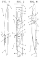
- the encoder gripper 1 which is shown in FIGS. 1 to 7, is used to insert a weft thread 25 in a rapier weaving machine into a shed 34 formed from warp threads 33.
- the encoder gripper 1 is, for example, in a known manner Screws 45 at the front end of a gripper belt 2 attached.
- the gripper belt 2 is not shown Means pushed into the shed 34 and out of the shed 34 pulled out again, so that the encoder gripper 1 accordingly is moved into and out of the shed 34.
- the encoder gripper 1 has a tubular base body Sections 3, 4, 5, 5 and 7, which are part of a one-piece, are bent metal plate.
- the base body has a side wall 8 two overlapping sections 3 and 7, a section 4 forming the bottom, an opposite section Side wall 9 forming section 5 and the top forming section 6.
- the metal plate can for example, from a deformable steel or a deformable Light metal, for example an aluminum alloy, consist.
- the first side wall 8, the two each other overlapping sections 3, 7 is located in Operation, for example, on the side facing the fabric 31, while the other side wall 9 of a reed 32 Rapier loom is facing.
- the foremost end 21 of the Encoder gripper 1, which is located in the area of the side wall 9, is therefore also on the reed 32 facing Page. Sections 4 and 6 are shown in the Embodiment provided with recesses 43 and 44.
- the two overlapping sections 3, 7 serve as a holder for a support element 12. Pass through two screws 10, 11 the two overlapping sections 3, 7 and are in the Support element 12 screwed in.
- Section 7, of which the Section 6 forming the upper side is located between the support member 12 and the section 3 by the the bottom forming portion 4 of the gripper 1 bent is.
- the support element 12 is with a guide element 13 for one Provide weft thread, for example in one piece with the Support element 12 is made.
- the guide element 13, starts at about a third of the height of the encoder gripper 1, ends in the area of the section 4 forming the bottom a stop 14.
- the support element 12 also forms with its underside stationary clamping element 15 for the weft thread 25 1 also contains a movable clamping element 16 with the stationary clamping element 15 for clamping a Weft thread 25 interacts.
- the movable clamping element 16 is by means of an intermediate bar 18 on the bottom portion 4 of the gripper 1 attached. This attachment can be done, for example Gluing done.
- the leaf spring-like, movable clamping element 16 is with a Stop part 19 provided, which is in the region of the support element 12 is located and through an opening 20 of the section 3 protrudes outwards. By means of the stop part 19, the movable clamping element 16 in the height of the stationary clamping element 15 be moved away from this by those of the Clamping elements 15, 16 formed thread clamp 17 to open.
- the Thread clamp 17 is located in the region of the side wall 8 of the Donor gripper 1, which faces the tissue 31.
- the stop part 19 works in a known manner with not shown Stop elements together, the encoder gripper 1 runs along these stop elements such that the stop part 19 is moved to open the thread clamp 17.
- the gripper 1 takes over a weft 25 in a known manner Way, between a fabric 31 and a feed member 35 is kept ready. With a forward movement of the encoder gripper 1 is the weft thread according to Fig. 1 along a guide 22 of section 5 up to a stop 23 guided. At the same time, the weft thread 25 is guided 24 of section 3, by means of the guide 27 of the section 6 and by means of the underside of the guide element 13 to its stop and one located in section 3 Stop 26 out.
- the weft 25 forms, for example between the stop 14 of the guide element 13 and the stop 23 of the section 5 an angle of about 50 ° to the section 4 forming the bottom.
- weft 25 between the clamping elements 15 and 16th the thread clamp 17 clamped between the stop 14 of the guide element 13 and the stop 26 of the section 3 are located.
- weft scissors (not shown) from the fabric separated and then from the encoder gripper 1 in the Shed 34 introduced.
- the weft 25 by one deducted stock, not shown, in particular one The feeder.
- the movable clamping element 16 loads the clamping element 15 with a force transmitted to the support member 12 and initiated by this in the base body of the master gripper 1 becomes.
- the weft thread 25 exercises over the guide element 13 Stop 14 and the thread clamp 17 also have a force the support element 12 made on the base body of the master gripper 1 is transmitted.
- the tube shape or box shape of the Basic body of the gripper 1 and the attachment of the Support element 12 on two overlapping sections 3, 7th offers the advantage that the base body introduced forces can easily catch and due to only a small extent of these forces is deformed. This makes it possible to keep the thickness of the metal plate low or a material, such as light metal, with only a small thickness to use.
- a movable clamping element 28 on a support element 29 is attached, which in turn on the two overlapping Sections 3, 7 is attached.
- the movable clamping element 28 is by means of its end a screw 30 attached to the support member 29.
- a clamping element 36 for example Glued attached.
- This clamping element 36 is with one longitudinal V-shaped rib 49 provided with a slot 48 of the movable clamping element 28 interacts.
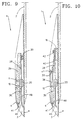
- FIGS 7 and 9 differs from the embodiment according to FIGS 7 in that the movable clamping element 28 only then Exerts force on the support member 29 in the base body of the gripper is initiated when the clamping element 28 over his stop part 19 is operated.
- the stop member 19 is controlled by means of slings 37, which are shown schematically in FIG. 8 are shown and which are arranged next to the encoder gripper 1 is, for example in the range of known, not shown Guide means for the gripper belt 2.
- the basic body the gripper is of course in the same Measure able to absorb the forces.
- In the front end of section 6 is a lip-shaped element 41 stamped.
- a slot 46 is provided in which the lip-shaped element 41 is inserted. This ensures that a Weft always guided along the guide element 13 is so that it is avoided that a weft thread between the Support element 12 and section 6 can reach.
- the support element 38 is loaded by a spring 40, which Support element 38 with the adjusting screw 39 to the section 6 presses.
- the leaf spring-like spring 40 has one end in the area of the movable clamping element 28 on the section 4 attached. The end of the spring 40 is together with the end of the clamping element 28 by means of a screw 20 on an intermediate piece 18 attached, for example to the section 4 is glued. The other end of the spring 40 loads this Support element 38.
- the support element 38 are brought into a predetermined angular position, after which the screw 10 is tightened to the support member 38 in this angular position on the two overlapping Sections 3, 7 to attach. That way it can Support element 38 brought into a predetermined angular position be adapted to the weft 25 to be clamped. Since this also changes the position of the guide element 13 changed, the lip-shaped element 41 is advantageous, the is inserted into the slot 46.
- the invention is not limited to those described by way of example and embodiments shown in the figures. Rather, other constructions are easily conceivable. For example, no one-piece metal plate is required become. Rather, the metal plate can consist of several Parts to be put together. Protection is provided only by the attached claims determined.
Landscapes
- Engineering & Computer Science (AREA)
- Textile Engineering (AREA)
- Looms (AREA)
Description
- Fig. 1
- zeigt eine perspektivische Darstellung eines erfindungsgemäßen Gebergreifers,
- Fig. 2
- eine Draufsicht auf den Gebergreifer der Fig. 1,
- Fig. 3
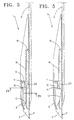
- einen Schnitt entlang der Linie III-III der Fig. 2 in vereinfachter Darstellung,
- Fig. 4
- einen Schnitt entlang der Linie IV-IV der Fig. 3 in vereinfachter Darstellung,
- Fig. 5
- einen Schnitt entlang der Linie V-V der Fig. 4 in vereinfachter Darstellung,
- Fig. 6
- eine Ansicht des Gebergreifers in Richtung des Pfeiles F6 der Fig. 1,
- Fig. 7
- eine Ansicht des Gebergreifers in Richtung des Pfeiles F7 der Fig. 1,
- Fig. 8
- eine abgewandelte Ausführungsform ähnlich Fig. 3 mit einer geöffneten Fadenklemme,
- Fig. 9
- einen Schnitt entlang der Linie IX-IX der Fig. 8 und
- Fig. 10
- eine Ausführungsform ähnlich der Darstellung nach Fig. 9 mit geschlossener Fadenklemme.
Claims (10)
- Gebergreifer für ein Greiferwebmaschine mit einem rohrförmigen, aus Metall gebildeten Grundkörper, der wenigstens eine Fadenklemme enthält, dadurch gekennzeichnet, daß der Grundkörper aus einer einteiligen Metallplatte (3, 4, 5, 6, 7) geformt ist und wenigstens zwei einander überlappende Abschnitte (3, 7) aufweist, die fest miteinander verbunden sind.
- Gebergreifer nach Anspruch 1, dadurch gekennzeichnet, daß die einander überlappenden Abschnitte (3, 7) sich im Bereich einer Seitenwand (8) des Grundkörpers befinden.
- Gebergreifer nach Anspruch 1 oder 2, dadurch gekennzeichnet, daß die einander überlappenden Abschnitte (3, 7) als Halterung für ein oder mehrere Bauelemente (12, 29, 38) dienen.
- Gebergreifer nach Anspruch 3, dadurch gekennzeichnet, daß das Bauelement (12, 29, 38) mittels wenigstens einer Schraube (10, 11) befestigt ist, die die überlappenden Abschnitte (3, 7) durchdringt und die Abschnitte miteinander und mit dem Bauelement (12, 29, 38) verbindet.
- Gebergreifer nach Anspruch 3 oder 4, dadurch gekennzeichnet, daß das Bauelement (12) ein einen Schußfaden (25) innerhalb des Grundkörpers positionierendes Führungselement (13) enthält.
- Gebergreifer nach einem der Ansprüche 3 bis 5, dadurch gekennzeichnet, daß das Bauelement (12) ein stationäres Klemmelement (15, 36) für ein Schußfaden (25) enthält.
- Gebergreifer nach Anspruch 6, dadurch gekennzeichnet, daß dem stationären Klemmelement (15, 36) ein bewegliches Klemmelement (16, 28) zugeordnet ist.
- Gebergreifer nach Anspruch 7, dadurch gekennzeichnet, daß das bewegliche Klemmelement (28) an dem Bauelement (29) gehalten ist.
- Gebergreifer nach einem der Ansprüche 3 bis 8, dadurch gekennzeichnet, daß das Bauelement (38) einstellbar gehalten ist.
- Gebergreifer nach einem der Ansprüche 1 bis 9, dadurch gekennzeichnet, daß das bewegliche Klemmelement (16, 28) mit einem Anschlagteil (19) versehen ist, das durch eine Aussparung (20) einer Seitenwand (8) des Grundkörpers nach außen ragt.
Applications Claiming Priority (3)
| Application Number | Priority Date | Filing Date | Title |
|---|---|---|---|
| BE9700797A BE1011480A3 (nl) | 1997-10-03 | 1997-10-03 | Gevergrijper voor een grijperweefmachine. |
| BE9700797 | 1997-10-03 | ||
| PCT/EP1998/005996 WO1999018274A1 (de) | 1997-10-03 | 1998-09-19 | Gebergreifer für eine greiferwebmaschine |
Publications (2)
| Publication Number | Publication Date |
|---|---|
| EP1019573A1 EP1019573A1 (de) | 2000-07-19 |
| EP1019573B1 true EP1019573B1 (de) | 2002-11-20 |
Family
ID=3890759
Family Applications (1)
| Application Number | Title | Priority Date | Filing Date |
|---|---|---|---|
| EP98951441A Expired - Lifetime EP1019573B1 (de) | 1997-10-03 | 1998-09-19 | Gebergreifer für eine greiferwebmaschine |
Country Status (6)
| Country | Link |
|---|---|
| US (1) | US6227259B1 (de) |
| EP (1) | EP1019573B1 (de) |
| JP (1) | JP2001519485A (de) |
| BE (1) | BE1011480A3 (de) |
| DE (1) | DE59806373D1 (de) |
| WO (1) | WO1999018274A1 (de) |
Families Citing this family (6)
| Publication number | Priority date | Publication date | Assignee | Title |
|---|---|---|---|---|
| US6453952B1 (en) * | 1998-10-21 | 2002-09-24 | Picanol, N.V. | Thread gripper for a rapier of a rapier loom |
| DE10018939A1 (de) * | 2000-04-17 | 2001-10-18 | Picanol Nv | Greifergehäuse für einen Greifer einer Webmaschine |
| EP1394302B1 (de) * | 2002-08-30 | 2007-06-20 | Promatech S.p.A. | Verbesserungen an Schussfadengreifern für Webmaschinen und an Webmaschinen mit Führungsmitteln dafür |
| EP1923494B1 (de) | 2002-09-20 | 2012-02-08 | Picanol | Gebergreifer für eine Greiferwebmaschine |
| EP1918437A1 (de) * | 2006-11-02 | 2008-05-07 | Sultex AG | Verfahren und Vorrichtung zum Eintragen eines Schussfadens |
| EP2037023A1 (de) * | 2007-09-12 | 2009-03-18 | Sultex AG | Fadenklemme für einen Greiferkopf und Verfahren zum Betreiben derselben |
Family Cites Families (7)
| Publication number | Priority date | Publication date | Assignee | Title |
|---|---|---|---|---|
| FR2132560B1 (de) * | 1971-04-05 | 1973-11-23 | Diederichs Sa Ateliers | |
| US3931837A (en) * | 1975-03-05 | 1976-01-13 | Rockwell International Corporation | Carrier for shuttleless loom |
| US3934621A (en) * | 1975-03-18 | 1976-01-27 | Rockwell International Corporation | Carrier for shuttleless looms |
| FR2337775A1 (fr) * | 1975-09-29 | 1977-08-05 | Et.Co.Ma Sarl | Pince de tirage auto-serrante pour passe-trame |
| US4259997A (en) * | 1979-11-07 | 1981-04-07 | Rockwell International Corporation | Weft carrier |
| DE3375806D1 (en) * | 1983-12-14 | 1988-04-07 | Rueti Ag Maschf | Weft inserting device for a needle loom |
| EP0248486B1 (de) * | 1986-06-03 | 1990-01-17 | Picanol N.V. | Bringergreifer für Greiferwebmaschinen |
-
1997
- 1997-10-03 BE BE9700797A patent/BE1011480A3/nl not_active IP Right Cessation
-
1998
- 1998-09-19 DE DE59806373T patent/DE59806373D1/de not_active Expired - Lifetime
- 1998-09-19 US US09/508,526 patent/US6227259B1/en not_active Expired - Fee Related
- 1998-09-19 WO PCT/EP1998/005996 patent/WO1999018274A1/de not_active Ceased
- 1998-09-19 JP JP2000515056A patent/JP2001519485A/ja active Pending
- 1998-09-19 EP EP98951441A patent/EP1019573B1/de not_active Expired - Lifetime
Also Published As
| Publication number | Publication date |
|---|---|
| DE59806373D1 (de) | 2003-01-02 |
| US6227259B1 (en) | 2001-05-08 |
| WO1999018274A1 (de) | 1999-04-15 |
| EP1019573A1 (de) | 2000-07-19 |
| BE1011480A3 (nl) | 1999-10-05 |
| JP2001519485A (ja) | 2001-10-23 |
Similar Documents
| Publication | Publication Date | Title |
|---|---|---|
| EP0146663B1 (de) | Bringergreifer für eine Greiferwebmaschine | |
| DE2541990B2 (de) | Übernahmegreifer fur Webmaschinen | |
| EP1019573A1 (de) | Gebergreifer für eine greiferwebmaschine | |
| CH670262A5 (de) | ||
| CH669220A5 (de) | Greifer fuer den schussfadeneintrag bei einer greiferwebmaschine. | |
| EP0769580A2 (de) | Fadenhalter für einen Bringergreifer | |
| WO2004057076A1 (de) | Weblitze | |
| EP1127181B2 (de) | Fadenklemme für einen greifer einer greiferwebmaschine | |
| EP1220960B1 (de) | Nehmergreifer für eine greiferwebmaschine | |
| DE4041212C1 (en) | Holding grip for car inner compartment - has end fasteners, each as cover plate inserted firmly on guide shaft | |
| DE4326642A1 (de) | Verbindungseinrichtung für Profilteile | |
| DE102020118163A1 (de) | Befestigungsmittel für Bandkanal einer Umreifungsmaschine | |
| DE19858013C2 (de) | Verbindung zwischen Schaftstab und Seitenstütze bei Webschäften mit reiterlosem Schaft-Litzensystem | |
| EP1108080B1 (de) | Greiferbandwebmaschine mit wenigstens einem greiferband und führungsmitteln | |
| DE19838781A1 (de) | Nehmergreifer für eine Greiferbandwebmaschine | |
| DE4342070C1 (de) | Haltevorrichtung für ein Andrückrollengehänge | |
| EP0395971A1 (de) | Federbügelzirkel | |
| DE2050263C3 (de) | Webschützen | |
| EP0811712A1 (de) | Fadenklemme für einen Bringergreifer und Bringergreifer mit Fadenklemme | |
| EP0980448A1 (de) | Greiferwebmaschine | |
| DE2310874C3 (de) | Webschützen | |
| DE1535898C (de) | Fadenbremse fur Webschützen | |
| DE3536868A1 (de) | Verbindungselement fuer einen schaftrahmen einer webmaschine | |
| EP1123430B1 (de) | Greiferwebmaschine mit wenigstens einem greiferband und führungsmitteln | |
| WO2000011250A1 (de) | Greiferbandwebmaschine |
Legal Events
| Date | Code | Title | Description |
|---|---|---|---|
| PUAI | Public reference made under article 153(3) epc to a published international application that has entered the european phase |
Free format text: ORIGINAL CODE: 0009012 |
|
| 17P | Request for examination filed |
Effective date: 20000228 |
|
| AK | Designated contracting states |
Kind code of ref document: A1 Designated state(s): CH DE FR GB IT LI |
|
| 17Q | First examination report despatched |
Effective date: 20010406 |
|
| GRAG | Despatch of communication of intention to grant |
Free format text: ORIGINAL CODE: EPIDOS AGRA |
|
| GRAG | Despatch of communication of intention to grant |
Free format text: ORIGINAL CODE: EPIDOS AGRA |
|
| GRAH | Despatch of communication of intention to grant a patent |
Free format text: ORIGINAL CODE: EPIDOS IGRA |
|
| GRAH | Despatch of communication of intention to grant a patent |
Free format text: ORIGINAL CODE: EPIDOS IGRA |
|
| GRAA | (expected) grant |
Free format text: ORIGINAL CODE: 0009210 |
|
| AK | Designated contracting states |
Kind code of ref document: B1 Designated state(s): CH DE FR GB IT LI |
|
| PG25 | Lapsed in a contracting state [announced via postgrant information from national office to epo] |
Ref country code: GB Free format text: LAPSE BECAUSE OF FAILURE TO SUBMIT A TRANSLATION OF THE DESCRIPTION OR TO PAY THE FEE WITHIN THE PRESCRIBED TIME-LIMIT Effective date: 20021120 |
|
| REG | Reference to a national code |
Ref country code: GB Ref legal event code: FG4D Free format text: NOT ENGLISH |
|
| REG | Reference to a national code |
Ref country code: CH Ref legal event code: NV Representative=s name: PATENTANWALTSBUERO G. PETSCHNER Ref country code: CH Ref legal event code: EP |
|
| REF | Corresponds to: |
Ref document number: 59806373 Country of ref document: DE Date of ref document: 20030102 |
|
| GBV | Gb: ep patent (uk) treated as always having been void in accordance with gb section 77(7)/1977 [no translation filed] |
Effective date: 20021120 |
|
| ET | Fr: translation filed | ||
| PLBE | No opposition filed within time limit |
Free format text: ORIGINAL CODE: 0009261 |
|
| STAA | Information on the status of an ep patent application or granted ep patent |
Free format text: STATUS: NO OPPOSITION FILED WITHIN TIME LIMIT |
|
| 26N | No opposition filed |
Effective date: 20030821 |
|
| REG | Reference to a national code |
Ref country code: CH Ref legal event code: NV Representative=s name: ZIMMERLI, WAGNER & PARTNER AG |
|
| REG | Reference to a national code |
Ref country code: CH Ref legal event code: PFA Owner name: PICANOL N.V. Free format text: PICANOL N.V.#POLENLAAN 3-7#8900 IEPER (BE) -TRANSFER TO- PICANOL N.V.#POLENLAAN 3-7#8900 IEPER (BE) |
|
| PGFP | Annual fee paid to national office [announced via postgrant information from national office to epo] |
Ref country code: CH Payment date: 20110926 Year of fee payment: 14 |
|
| REG | Reference to a national code |
Ref country code: DE Ref legal event code: R082 Ref document number: 59806373 Country of ref document: DE Representative=s name: PATENTANWAELTE RUFF, WILHELM, BEIER, DAUSTER &, DE |
|
| REG | Reference to a national code |
Ref country code: DE Ref legal event code: R082 Ref document number: 59806373 Country of ref document: DE Representative=s name: PATENTANWAELTE RUFF, WILHELM, BEIER, DAUSTER &, DE Effective date: 20120814 Ref country code: DE Ref legal event code: R081 Ref document number: 59806373 Country of ref document: DE Owner name: PICANOL, BE Free format text: FORMER OWNER: PICANOL N.V., IEPER, BE Effective date: 20120814 |
|
| PGFP | Annual fee paid to national office [announced via postgrant information from national office to epo] |
Ref country code: IT Payment date: 20120925 Year of fee payment: 15 Ref country code: DE Payment date: 20120926 Year of fee payment: 15 |
|
| PGFP | Annual fee paid to national office [announced via postgrant information from national office to epo] |
Ref country code: FR Payment date: 20121008 Year of fee payment: 15 |
|
| REG | Reference to a national code |
Ref country code: CH Ref legal event code: NV Representative=s name: WAGNER PATENT AG, CH |
|
| REG | Reference to a national code |
Ref country code: CH Ref legal event code: PL |
|
| REG | Reference to a national code |
Ref country code: FR Ref legal event code: ST Effective date: 20140530 |
|
| REG | Reference to a national code |
Ref country code: DE Ref legal event code: R119 Ref document number: 59806373 Country of ref document: DE Effective date: 20140401 |
|
| PG25 | Lapsed in a contracting state [announced via postgrant information from national office to epo] |
Ref country code: LI Free format text: LAPSE BECAUSE OF NON-PAYMENT OF DUE FEES Effective date: 20130930 Ref country code: CH Free format text: LAPSE BECAUSE OF NON-PAYMENT OF DUE FEES Effective date: 20130930 |
|
| PG25 | Lapsed in a contracting state [announced via postgrant information from national office to epo] |
Ref country code: DE Free format text: LAPSE BECAUSE OF NON-PAYMENT OF DUE FEES Effective date: 20140401 Ref country code: FR Free format text: LAPSE BECAUSE OF NON-PAYMENT OF DUE FEES Effective date: 20130930 Ref country code: IT Free format text: LAPSE BECAUSE OF NON-PAYMENT OF DUE FEES Effective date: 20130919 |